19 February 2016
ASEK-1335-T-KIT Page 1of 5
ASEK-1335-T-KIT Quick Guide
The ASEK-1335-T-KIT as described below is for the purpose of evaluating the A1335 device.
ASEK-1335-T-KIT Bill of Materials
ASEK-20 Kit (Part # 85-0540-600)
oASEK-20 Chassis with main Motherboard inside (85-0540-004)
oUSB Communications Cable
oDC Power Supply/Cable with AC Outlet Adapters
oProto Board ( Part # 85-0540-103)
oRibbon Cable (Part # 85-0540-300)
ASEK-1335-SUBKIT-T:
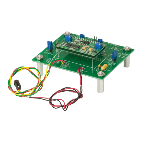
oA1335 Daughterboard (Part #: 85-0540-109 / Stenciled A1332)
oA1335 Socketed single die grand-daughter board (Part #: 85-0723 / Stenciled
ASEK1335-SD)
oA1335 Socketed dual die grand-daughter board (Part #: 85-0716)
Figure 2. ASEK-1335-SUBKIT-T
Instructions for Configuring ASEK-1335-T-KIT with Device On-Board
1. Connect one end of the USB communications cable to a personal computer
2. Connect the other end of the USB communications cable to the “USB” port on the ASEK-20 chassis
3. Connect the ribbon cable to the J2 connector on the daughterboard (85-0540-109)
4. Connect the other end of the ribbon cable to the “Device Connection” port on the ASEK-20 chassis
5. Mount the socketed grand-daughterboard (either 85-0723 or 85-716) onto the daughter board (85-
0540-109)
