ST STEVAL-IPC002V1 User manual

June 2010 Doc ID 16916 Rev 1 1/30
UM0886
User manual
STEVAL-IPC002V1 demonstration board
for parking ticket vending machine
Introduction
A parking ticket vending machine is a hand-held, battery operated device, inside of which a
thermal printer is interfaced with the STM32 microcontroller from STMicroelectronics. This
document focuses on the STEVAL-IPC002V1 demonstration board, whose objective is to
print and generate parking tickets for different types of vehicles. The application can easily
be modified to suit other applications where paper printing is to be managed directly by the
microcontroller, such as POS-based applications, railway and bus ticket printing
applications, standalone printers, and the like.
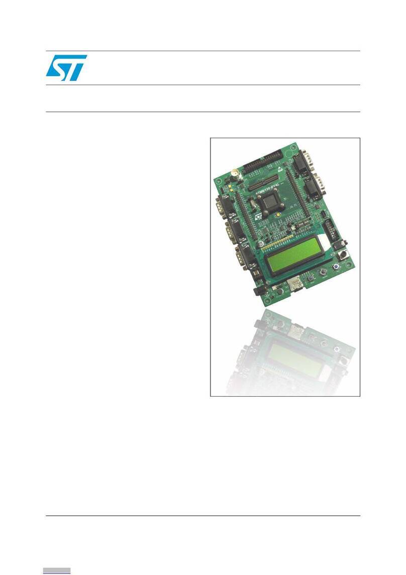
Figure 1. STM32-based parking ticket vending machine
The thermal printer has an in-built stepper motor for thermal paper feeding, paper
movement, and so on. The stepper motor is controlled by a dedicated stepper-motor driver
with an SPI interface. The system operates on two Li-Ion batteries and an optional DC
adaptor. On-board battery chargers are available to charge the batteries from the DC
adaptor. The data to be printed is entered by way of touch keys, and can be verified on an
alphanumeric LCD.
www.st.com

Contents UM0886
2/30 Doc ID 16916 Rev 1
Contents
1 Definitions . . . . . . . . . . . . . . . . . . . . . . . . . . . . . . . . . . . . . . . . . . . . . . . . . 4
2 Features . . . . . . . . . . . . . . . . . . . . . . . . . . . . . . . . . . . . . . . . . . . . . . . . . . . 5
3 Getting started . . . . . . . . . . . . . . . . . . . . . . . . . . . . . . . . . . . . . . . . . . . . . . 6
3.1 Package . . . . . . . . . . . . . . . . . . . . . . . . . . . . . . . . . . . . . . . . . . . . . . . . . . . 6
3.2 Hardware installation . . . . . . . . . . . . . . . . . . . . . . . . . . . . . . . . . . . . . . . . . 6
3.3 Hardware layout . . . . . . . . . . . . . . . . . . . . . . . . . . . . . . . . . . . . . . . . . . . . . 9
4 System overview . . . . . . . . . . . . . . . . . . . . . . . . . . . . . . . . . . . . . . . . . . . 12
4.1 Hardware design . . . . . . . . . . . . . . . . . . . . . . . . . . . . . . . . . . . . . . . . . . . 12
4.1.1 Microcontroller(STM32) . . . . . . . . . . . . . . . . . . . . . . . . . . . . . . . . . . . . . 12
4.1.2 Battery connector . . . . . . . . . . . . . . . . . . . . . . . . . . . . . . . . . . . . . . . . . . 12
4.1.3 Thermal printer (FM205-HS) . . . . . . . . . . . . . . . . . . . . . . . . . . . . . . . . . 12
4.1.4 Alphanumeric LCD . . . . . . . . . . . . . . . . . . . . . . . . . . . . . . . . . . . . . . . . . 13
4.1.5 EEPROM . . . . . . . . . . . . . . . . . . . . . . . . . . . . . . . . . . . . . . . . . . . . . . . . 13
4.1.6 S-Touch-based keypad . . . . . . . . . . . . . . . . . . . . . . . . . . . . . . . . . . . . . 14
4.1.7 Power supply unit . . . . . . . . . . . . . . . . . . . . . . . . . . . . . . . . . . . . . . . . . . 14
4.2 Flowchart . . . . . . . . . . . . . . . . . . . . . . . . . . . . . . . . . . . . . . . . . . . . . . . . . 15
4.3 Hardware schematics . . . . . . . . . . . . . . . . . . . . . . . . . . . . . . . . . . . . . . . . 17
5 Bill of materials . . . . . . . . . . . . . . . . . . . . . . . . . . . . . . . . . . . . . . . . . . . . 21
6 Revision history . . . . . . . . . . . . . . . . . . . . . . . . . . . . . . . . . . . . . . . . . . . 29

UM0886 List of figures
Doc ID 16916 Rev 1 3/30
List of figures
Figure 1. STM32-based parking ticket vending machine . . . . . . . . . . . . . . . . . . . . . . . . . . . . . . . . . . . 1
Figure 2. STM32-based parking ticket vending machine demonstration board . . . . . . . . . . . . . . . . . . 7
Figure 3. S-Touch-based keypad. . . . . . . . . . . . . . . . . . . . . . . . . . . . . . . . . . . . . . . . . . . . . . . . . . . . . 8
Figure 4. Sample printed ticket . . . . . . . . . . . . . . . . . . . . . . . . . . . . . . . . . . . . . . . . . . . . . . . . . . . . . . 8
Figure 5. Hardware layout: main board - top side . . . . . . . . . . . . . . . . . . . . . . . . . . . . . . . . . . . . . . . . 9
Figure 6. Hardware layout: main board - bottom side . . . . . . . . . . . . . . . . . . . . . . . . . . . . . . . . . . . . 10
Figure 7. Hardware layout: daughterboard S-Touch keypad - top side . . . . . . . . . . . . . . . . . . . . . . . 10
Figure 8. Hardware layout: daughterboard S-Touch keypad - bottom side . . . . . . . . . . . . . . . . . . . . 11
Figure 9. Block diagram of an STM32-based parking ticket vending machine . . . . . . . . . . . . . . . . . 12
Figure 10. Truth table for excitation sequence. . . . . . . . . . . . . . . . . . . . . . . . . . . . . . . . . . . . . . . . . . . 13
Figure 11. Timing diagram for excitation sequence . . . . . . . . . . . . . . . . . . . . . . . . . . . . . . . . . . . . . . . 13
Figure 12. Power block of STM32-based parking ticket vending machine . . . . . . . . . . . . . . . . . . . . . 14
Figure 13. Voltage regulators used in power block . . . . . . . . . . . . . . . . . . . . . . . . . . . . . . . . . . . . . . . 14
Figure 14. Flowchart . . . . . . . . . . . . . . . . . . . . . . . . . . . . . . . . . . . . . . . . . . . . . . . . . . . . . . . . . . . . . . 15
Figure 15. Schematic: microcontroller section . . . . . . . . . . . . . . . . . . . . . . . . . . . . . . . . . . . . . . . . . . . 17
Figure 16. Schematic: motor driver . . . . . . . . . . . . . . . . . . . . . . . . . . . . . . . . . . . . . . . . . . . . . . . . . . . 18
Figure 17. Schematic: connectors (printer, LCD and JTAG) . . . . . . . . . . . . . . . . . . . . . . . . . . . . . . . . 18
Figure 18. Schematic: power management section . . . . . . . . . . . . . . . . . . . . . . . . . . . . . . . . . . . . . . . 19
Figure 19. Schematic: S-Touch keypad. . . . . . . . . . . . . . . . . . . . . . . . . . . . . . . . . . . . . . . . . . . . . . . . 20

Definitions UM0886
4/30 Doc ID 16916 Rev 1
1 Definitions
Table 1. Definitions
Acronym Definition
ESD Electrostatic discharge
I2C Inter-integrated circuit
JTAG Joint test action group
LCD Liquid crystal display
MCU Microcontroller unit
POS Point of sale
PTVM Parking ticket vending machine
RTC Real time clock
SPI Serial peripheral interface

UM0886 Features
Doc ID 16916 Rev 1 5/30
2 Features
The STM32-based demonstration board has the following key features.
●Thermal printer interfaced through SPI2.
●Stepper motor driver interfaced through SPI1 used to rotate the printer head while
printing.
●S-Touch™-based keypad for user interfacing. The S-Touch™ controller device is
interfaced through the I2C2. The keypad is used to enter the vehicle number and other
parameters, and set the date and time.
●LED indication for battery status.
●On-board JTAG connector for firmware upgrades and changes.
●Alphanumeric LCD for displaying numbers and settings entered through the S-Touch™
keypad.
●SPDT switch for switching the system ON and OFF.
●Push button switch for resetting the system.
●Rechargeable battery circuit.
●On-board power supply. The entire system can be powered by either a DC adaptor
(9 V, 2.5 A) or battery (2 batteries of 3.7 V each, 1.8 Ah ratings).
●Thermistor to monitor the temperature of the thermal head.
●STM32 in-built RTC (real time clock) that provides date and time of printing.
●EEPROM interfaced through I2C1. The last 20 vehicle numbers are stored in the
EEPROM.

Getting started UM0886
6/30 Doc ID 16916 Rev 1
3 Getting started
3.1 Package
The STM32-based parking ticket vending machine demonstration board includes the
following items.
●Hardware:
– demonstration board
●Documentation:
– this user manual
– schematics, gerber files, BOM
●Firmware:
– pre-programmed STM32 device soldered on the demonstration board
– object files for the firmware
3.2 Hardware installation
The following instructions are for setting-up the STM32-based parking ticket vending
machine demonstration board.
1. Connect the 9 V, 2.5 A DC adaptor or connect two Li-Ion batteries (3.7 V, 1800 mAH) to
the connectors B1+, B1-, B2+ and B2-.
2. Feed the thermal paper (50 to 52 mm width) with the glossy (thermal printing) side up
as shown in Figure 2.
Note: Avoid running the demonstration board without inserting the thermal paper since this can
cause the printer to overheat and cause permanent damage.
3. Switch on the board (SPDT ON/OFF power switch).
You should now see the word "VEHICLE" on the LCD.
4. Select the vehicle type by pressing one of the following key combinations.
– 4 WHL: FUNC + 1
– 2 WHL: FUNC + 2
– HEAVY FUNC + 3
For example, to select a 4 WHL type vehicle, press "FUNC" (function key) and then "1".
The selected vehicle type is displayed on the LCD for 1 second.
5. The word "ENTRY" appears on the LCD. Press one of the following key combinations
to select the entry type.
– SINGLE: FUNC + 7
– PASS: FUNC + 8
The selected entry type is displayed on the LCD for 1 second.
6. Enter the vehicle number (last 4 digits) by pressing the corresponding numeric keys on
the keypad.
The number is now displayed on the LCD.
7. Send the print command by pressing the PRINT function (FUNC + 0).
The ticket is printed.
UM0886 Getting started
Doc ID 16916 Rev 1 7/30
The time can be set by pressing the SET function (FUNC + 9).
The 9 V adaptor is used to charge the batteries through the on-board battery charger.
To see the last 20 entries, press "FUNC" and then "6".
Figure 2. STM32-based parking ticket vending machine demonstration board
8. To replace the thermal paper, pull the black roll out of the printer. Place the paper (50 to
52 mm width) so that the glossy side faces up as shown in Figure 2. Put the black roll
back into place. If the paper is not inserted correctly the printout may not come out
properly.
!-V
4HERMALPAPER
4HERMALPRINTER
!LPHANUMERIC,#$
3TEPPERMOTORDRIVER
34-
*4!'CONNECTOR
0OWERONOFF30$4
34OUCHKEYBOARD
0OWER*ACK
"ATTERYCONNECTORS
2ELAY

Getting started UM0886
8/30 Doc ID 16916 Rev 1
Figure 3. S-Touch-based keypad
The vehicles are categorized as follows:
●4 WHL = 4-wheelers (cars)
●2 WHL = 2-wheelers (bikes and scooters)
●HEAVY = heavy vehicles such as trucks or buses
The entry types are:
●Single = single entry/exit
●PASS = the user has a pass for multiple entries and exits.
Figure 4 shows a sample printed ticket generated from the PTVM.
Figure 4. Sample printed ticket
!-V
%3#ESCAPEKEY
&5.##,2
7(,&5.#
7(,&5.#
(%!69&5.#
#,2CLEARKEY
-%-/29&5.#
&5.#FUNCTIONKEY
0!33&5.#
3%4&5.#
3).',%&5.#
02).4&5.#

UM0886 Getting started
Doc ID 16916 Rev 1 9/30
3.3 Hardware layout
The STM32-based parking ticket vending machine demonstration board is built using
STMicroelectronics' ARM® Cortex-M3 core-based STM32F103RBT6 in a 64-pin LQFP64
package. The components used on this board are listed below. Figure 5 and Figure 6
provide the component layouts to assist you in locating the different component sections on
the board.
●ST components:
– STM32F103RBT6 (32-bit MCU)
– L9935 (stepper motor driver)
– STMPE1208S (S-Touch keypad)
– M24C01-W (EEPROM)
– L6924D (battery charger)
– L5987A (step-down voltage regulator)
– STM1061N31WX6F (low-power voltage detector for battery monitoring)
●Non-ST components:
– FM205-HS (thermal printer)
– 16X2 alphanumeric LCD
Refer to the bill of materials in Chapter 5 for a detailed list of components.
Figure 5. Hardware layout: main board - top side

Getting started UM0886
10/30 Doc ID 16916 Rev 1
Figure 6. Hardware layout: main board - bottom side
Figure 7. Hardware layout: daughterboard S-Touch keypad - top side

UM0886 Getting started
Doc ID 16916 Rev 1 11/30
Figure 8. Hardware layout: daughterboard S-Touch keypad - bottom side

System overview UM0886
12/30 Doc ID 16916 Rev 1
4 System overview
4.1 Hardware design
Figure 9. Block diagram of an STM32-based parking ticket vending machine
As shown in Figure 9, the principal system controller is the STM32 microcontroller.
Figure 12 and Figure 13 show the power management blocks in more detail.
4.1.1 Microcontroller(STM32)
The STM32 is a 32-bit MCU based on the popular ARM 32-bit Cortex™-M3 CPU running at
72 MHz with a performance of 90 DMIPS with 1.25 DMIPS/MHz. The microcontroller
incorporates single-cycle multiplication and hardware division functions. It has 80 fast
general-purpose IOs to enhance the overall performance. The IOs are 5-volt tolerant.
The microcontroller has several communication interfaces, including multiple I2Cs, USARTs
(4.5 Mbps) and SPIs, a CAN 2.0B active interface and a USB 2.0 interface. For more
information, go to http://www.st.com.
The microcontroller works on a single voltage ranging from 2 to 3.6 V, unlike some other
microcontrollers that require a dual voltage. In this application the system operates at 3.3 V.
4.1.2 Battery connector
B1+ and B1-, B2+ and B2- are the four pins of the battery connector. Two Li-Ion batteries of
3.7 V and 1800 mAh each are to be connected with correct polarity.
4.1.3 Thermal printer (FM205-HS)
The thermal printer is a compact, high-speed thermal line dot printing mechanism. It can be
used with a measuring instrument and analyzer, a POS, a communication device or a data
terminal device.

UM0886 System overview
Doc ID 16916 Rev 1 13/30
The paper is fed in a forward direction when the motor shaft is rotating in the normal
direction (clockwise) as seen from the motor gear side. The motor is driven by a 2-2 phase
excitation, constant-current chopper method and feeds 0.125 mm of paper (equivalent to a
single dot pitch) every two steps of the motor drive signal. It is not possible to print while the
motor is rotating in the reverse direction.
Excitation sequence
As shown in Figure 10, the printer feeds the paper in the normal direction when the motor is
excited in the order of step 1, step 2, step 3, step 4, step 1, step 2... On the other hand, to
rotate the motor in the reverse direction, the motor must be driven in the reverse order: step
4, step 3, step 2, step 1, step 4, step 3, etc.
Figure 10. Truth table for excitation sequence
Figure 11. Timing diagram for excitation sequence
4.1.4 Alphanumeric LCD
A 16 by 2 cm alphanumeric LCD displays the entries entered through the keypad.
4.1.5 EEPROM
The EEPROM maintains records and stores the last 20 entries.

System overview UM0886
14/30 Doc ID 16916 Rev 1
4.1.6 S-Touch-based keypad
The demonstration board incorporates an S-Touch keypad based on the STMPE1208SQTR
to navigate through the menus. This keypad is a 12-key daughterboard. Figure 3 shows the
placement of the keys.
4.1.7 Power supply unit
The power block is the main module of any hand-held system. This application requires
several voltages (3.3 V, 5 V, 6.5 V) to drive the various board components. The board can be
used in standalone/hand-held mode with two batteries. The circuit is implemented so that
the batteries are charged individually and in parallel by dedicated battery chargers, and
while discharging (application running on the batteries) they are connected in series. This
switching is done through a relay.
If the DC adaptor is plugged in, the voltage from the voltage regulator output excites the
relay, which changes the series connection of the batteries to a parallel connection and all
the power is taken from the adaptor.
Figure 12. Power block of STM32-based parking ticket vending machine
Figure 13. Voltage regulators used in power block

UM0886 System overview
Doc ID 16916 Rev 1 15/30
4.2 Flowchart
Figure 14 is a flowchart of the entire system.
Figure 14. Flowchart
!-V
,1,7,$/,=$7,21
57&&RQILJXUDWLRQ
*3,2¶V&RQILJXUDWLRQ
/&'&RQILJXUDWLRQ
67RXFK6HWWLQJV
67$57
,17(55837
&RQILJXUHH[WHUQDOOLQHLQWHUUXSWV
7RXFK(QGRISDSHU/RZEDWWHU\
,V3ULQW
)ODJ
6(7"
12
,V6HW
'DWH
)ODJ
6(7"
12
6WDUW3ULQWLQJ
<HV
6HW'DWH
<HV
$
$
67RXFK
5HVHWDQG5H
LQLWLDOL]H
%
,V(QWU\
)ODJ
6(7"
12
,V
9HKLFOH
)ODJ
6(7"
12
6HW(QWU\W\SH
<HV
6HW9HKLFOH 7\SH
<HV
,V
1XPEHU
)ODJ
6(7"
6HW9HKLFOH
1XPEHU
<HV
$
12

System overview UM0886
16/30 Doc ID 16916 Rev 1
●Start printing: the thermal printer starts printing stored data.
●Set Date: modify the date and time of the system.
●Set Entry Type: entry type 'Pass' or 'Single' is stored in the user buffer data.
●Set Vehicle Type: the vehicle type is 2 WHL, 4 WHL or Heavy, and is stored in the user
buffer data.
●Set Vehicle Number: the system stores the last 4 digits of the vehicle number entered
by the user.
Once all initializations are complete, various flag statuses are continuously checked within
the main state machine. When a key is pressed on the keypad, an interrupt is generated and
corresponding actions are taken by the firmware.

UM0886 System overview
Doc ID 16916 Rev 1 17/30
4.3 Hardware schematics
The following figures represent the schematic diagrams for the board.
Figure 15. Schematic: microcontroller section
!-V
60'B63,B026,
)06B67%B3&
26&B,1
60'B63,B6&.
26&B287
Q567
9 /&'B'B3%
%227B
)06B63,B026,
)06B63,B0,62
-7$*B3%
)06B63,B&/.
306B*B3$
-7$*B6:'B3%
)06B3(0B3$
)06B67%B3&
/&'B'B3&
-7$*B6:'B3$
-7$*B6:'B3$
-7$*B6:'B3$
%227B
9%$7
3&B26&B,1
3&B26&B287
)06B67%B3$
)06B/$7B3$
)06B67%B3$
)06B67%B3&
)06B67%B3&
676B,&B6'$
60'B&61B3$
60'B(1B3&
)06B70B$1B3&
676B7,17B3%
676B,&B6&/
/&'B(B3&
/&'B'B3&
/&'B'B3'
/&'B'B3%
/&'B'B3%
3&B26&B,1
3&B26&B287
26&B287
26&B,1
%227B
%227B
9
Q567
676B,&B6&/
676B,&B6'$
0&B:&B3&
670B287B3&
/&'B'B3$
/&'B'B3$
0&B,&B6&/
0&B,&B6'$
60'B63,B0,62
5(6(7B1
86$57B5;
/&'B56B3&
86$57B7;
86$57B7;
86$57B5;
/&'B6:,7&+B3%
9
9
9
9
9
9
9
0,&52&21752//(5
5
5
5 N
5 N
'
5('/('
'
5('/('
5
'10
5
'10
5
N
5
N
5
N
5
N
&
S)
&
S)
5
5
5
0
5
0
&
Q)
&
Q)
-
&21
-
&21
&
S)
&
S)
5
N
5
N
6:6:
<
0+]
<
0+]
5
N
5
N
5
N
5
N
&
Q)
&
Q)
5
5
&
Q)
&
Q)
<
.K]
<
.K]
670)5%7
8
670)5%7
8
9%$7
3&B$ 17,B7$03
3&B26 &B,1
3&B26 &B2 87
3'B26&B,1
3'B26&B287
Q567
3&
3&
3&
3&
966$
9''$
3$B :.83
3$
3$
3$
966B
9''B
3$
3$
3$
3$
3&
3&
3%
3%
3%
3%
3%
966B
9''B
9''B
966B
3$
3$
3$
3$
3$
3$
3&
3&
3&
3&
3%
3%
3%
3%
9''B
966B
3%
3%
%227
3%
3%
3%
3%
3%
3'
3&
3&
3&
3$
3$
&
Q)
&
Q)
&
Q)
&
Q)
&
S)
&
S)
&
S)
&
S)
&
Q)
&
Q)
&
X)
&
X)
/
X+
/
X+
&
Q)
&
Q)
5
N
5
N
%7%$77(5< %7%$77(5<

System overview UM0886
18/30 Doc ID 16916 Rev 1
Figure 16. Schematic: motor driver
Figure 17. Schematic: connectors (printer, LCD and JTAG)
!-V
60'B63,B026,
60'B63,B0,62
60'B63,B6&.
60'B)06B3+
60'B)06B3+
60'B&61B3$
60'B(1B3&
60'B)06B3+
60'B)06B3+
99
02725'5,9(5
&
Q)
&
Q)
8
/
8
/
*1'
287$
6&.
6',
6'2
9&&
&61
(1
287%
*1'
*1'
65%
287%
&'59
26&
96
1&
287$
65$
*1'
&
Q)
&
Q)
5
5
&
Q)
&
Q)
&
Q)
&
Q)
5
5
&
&$3
&
&$3
!-V
/&'B'B3$
/&'B'B3$
/&'B'B3%
/&'B'B3%
/&'B56B3&
/&'B(B3&
/&'B'B3&
/&'B'B3&
/&'B'B3'
/&'B'B3%
/('
57&.
9
'%*54
'%*$&.
-7$*B3%
-7$*B6: 'B3$
-7$*B6: 'B3$
-7$*B6: 'B3$
Q567
9
9
9
-7$*B6: 'B3%
9
/('
/&'B6: ,7&+B3%
9
/&'&211(&725
-7$*B&211
5
12786('
5
12786('
5
N
5
N
5
N
5
N
-
-7$*B&211
-
-7$*B&211
5
N5
N
5
5
&211/&'&211/&'
966
9''
&2175$67
56
5:5
(1
'
'
'
'
'
'
'
'
/('
/('
5
N
5
N
5
N
5
N
5
N
5
N
5
5
5 N
5 N
5
5
4
6773)9B3
4
6773)9B3
5
N
5
N
5
N
5
N
5
N
5
N
)06B63,B0,62
306B)06B9+
)06B67%B3&
)06B67%B3&
)06B67%B3&
9
)06B70B$1B3&
9
306B)06B9+
)06B67%B3&
)06B67%B3$
)06B67%B3$
)06B63,B026,
)06B/$7B3$
60'B)06B3+
60'B)06B3+
)06B63,B&/.
60'B)06B3+
60'B)06B3+
9
)06B3(0B3$
35,17(5&211(&725
5
.
5
.
&
X)
&
X)
5
5
5
N
5
N
&211
)06+6
&211
)06+6
3&$
3&2
3(0
1&
1&
9+
9+
',1
&/.
*1'
*1'
67%
67%
67%
9''
70
70
67%
67%
67%
*1'
*1'
/$7
'2
9+
9+
3+
3+
3+
3+

UM0886 System overview
Doc ID 16916 Rev 1 19/30
Figure 18. Schematic: power management section
!-V
9%$7B'&B$'
%
%
%
%
'&B$'
%
%
%
9%$7B287
9
9%$7B'&B$'
9%$7B'&B$'
5(*B287
9%$7B'&B$'9%$7B'&B$'
9%$7B287
'&B$' 670B287B3&9%$7B'&B$'
306B)06B9+
306B*B3$
306B)06B9+
9
9
Y
9
32:(56833/<6(&7,21
& 3)& 3)
--
6:
6:63'7
6:
6:63'7
5
N
5
N
8
/'B '3$.
8
/'B '3$.
*1'
,1
287
287
&
Q)
&
Q)
&
X)9
&
X)9
5
N
5
N
8
/' ' 75
8
/' ' 75
9,1
1&
9287
*1'
9287
9287
9287
1&
5
.
5
.
&
X)
&
X)
8 /$8 /$
287
6<1&+
,1+
&203
)%
)6:
*1'
9&&
5
N
5
N
&
Q)
&
Q)
&
X)9
&
X)9
5
5
/
X+$
/
X+$
&
X)
&
X)
8
6701
8
6701
287
966
9&&
5
N
5
N
'
6736/8
'
6736/8
-
&21
-
&21
&
Q)
&
Q)
4
6773)9B3
4
6773)9B3
5
N
5
N
8
/'B '3$.
8
/'B '3$.
*1'
,1
287
287
'
',2'(
'
',2'(
5
N
5
N
5
0
5
0
5
.
5
.
&
Q)
&
Q)
&
X)9
&
X)9
5
N
5
N
'
6736/
'
6736/
4
6763)/B3
4
6763)/B3
-
&21
-
&21
&
X)
&
X)
5
5
'
6736/8
'
6736/8
/6
5(/$<63'7
/6
5(/$<63'7
&
Q)
&
Q)

System overview UM0886
20/30 Doc ID 16916 Rev 1
Figure 19. Schematic: S-Touch keypad
!-V
6
6
6
6
6
6
6
6
6
6
6
6
6
6
6
6
6
6
6
6
6
5(6(7B1
6
6
6
676B,&B6'$
676B,&B6&/
676B7,17B3%
676B,&B6'$
676B,&B6&/
676B7,17B3%
5(6(7B1
Y
Y
Y
Y
728&+.(<6
'%B&2116703(66(&7,21
&
S)
&
S)
&
S)
&
S)
8
6703(6
8
6703(6
*3,2B
6B,1B
6B,1B
6B,1B
6B,1B
*3,2B
6B,1B
*3,2B
*3,2B
*3,2B
,'B
,'B
5(6(7B1
6B,1B
6B,1B
*3,2B
*3,2B
6'$7$
6&/.
7B,17
*B,17
%((3
7&/.
6B,1B
6B,1B
6B,1B
*1'
9
95(*
9
6B,1B
*3,2B
*3,2B
*3,2B
*3,2B
*3,2B
9
*1'
6B5()
6B,1B
&
S)
&
S)
&
S)
&
S)
3$ '
&21
3$ '
&21
&
S)
&
S)
&
S)
&
S)
3$ '
&21
3$ '
&21
&
S)
&
S)
&
S)
&
S)
&
S)
&
S)
&
S)
&
S)
-
&21
-
&21
&
S)
&
S)
3$ '
&21
3$ '
&21
3$ '
&21
3$ '
&21
3$ '
&21
3$ '
&21
5
N
5
N
3$ '
&21
3$ '
&21
3$ '
&21
3$ '
&21
-
&21
-
&21
&
X)9
&
X)9
&
S)
&
S)
3$ '
&21
3$ '
&21
3$ '
&21
3$ '
&21
3$ '
&21
3$ '
&21
3$ '
&21
3$ '
&21
&
S)
&
S)
&
Q)
&
Q)
3$ '
&21
3$ '
&21
Table of contents
Other ST Motherboard manuals

ST
ST NUCLEO-F411RE Manual

ST
ST STEVAL-IHM010V1 User manual

ST
ST STSW-S2LP-KNX-DK User manual

ST
ST STM32 Nucleo User manual

ST
ST UM1935 User manual

ST
ST STM32 Nucleo Installation and operating instructions

ST
ST STEVAL-SPIN3202 User manual

ST
ST STUSB02E User manual

ST
ST SPC582B-DIS User manual

ST
ST eMotion STEVAL-MKI109V1 User manual

ST
ST SPC5-UDESTK User manual

ST
ST SPC584B-DISP User manual

ST
ST NUCLEO-G070RB User manual

ST
ST M24LR64-R User manual

ST
ST STEVAL-ISC005V1 Administrator Guide

ST
ST STLINK-V3SET User manual

ST
ST SPC582B-DIS User manual

ST
ST STEVAL-DIGAFEV1 User manual

ST
ST STM32 Nucleo-32 User manual

ST
ST STM3210E-EVAL User manual