manuals.online logo
Brands
  1. Home
  2. •
  3. Brands
  4. •
  5. Allen-Bradley
  6. •
  7. Enclosure
  8. •
  9. Allen-Bradley 198E-A0S Series User guide

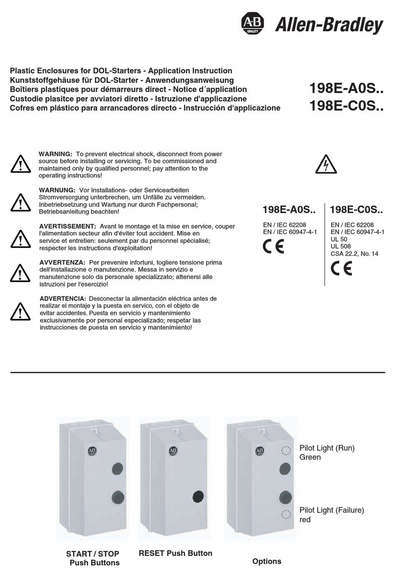
Allen-Bradley 198E-A0S Series User guide

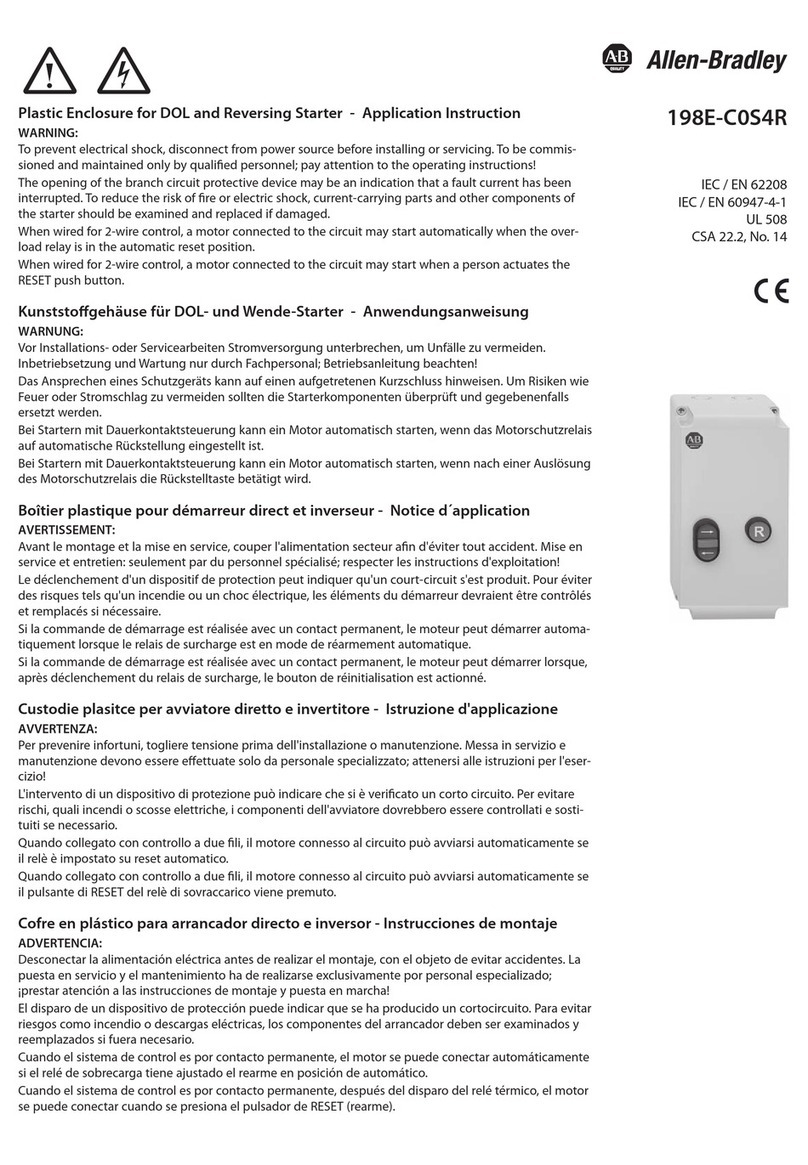
Plastic Enclosures for DOL-Starters - Application Instruction
Kunststogehäuse für DOL-Starter - Anwendungsanweisung
Boîtiers plastiques pour démarreurs direct - Notice d´application
Custodie in plastica per avviatori diretti - Istruzioni di applicazione
Cofre de plástico para arrancadores directos - Instrucciones de uso
198E-A0S..
198E-C0S..
198E-A0S..
EN / IEC 62208
EN / IEC 60947-4-1
UL 50
UL 60947-4-1
CAN/CSA-C22.2 No. 60947-4-1
EN / IEC 62208
EN / IEC 60947-4-1
ATTENTION:
To prevent electrical shock, disconnect from power source before installing or servicing.
To be commissioned and maintained only by qualied personnel; pay attention to the operating
instructions!
When wired for 2-wire control, a motor connected to the circuit may start automatically when the
overload relay is in the automatic reset position or when a person actuates the RESET push button.
ACHTUNG:
Um Unfälle zu vermeiden, vor Installations- oder Servicearbeiten die Stromversorgung unterbrechen.
Inbetriebsetzung und Wartung nur durch Fachpersonal; Betriebsanleitung beachten!
Bei Startern mit Dauerkontaktsteuerung kann ein Motor automatisch starten, wenn das
Motorschutzrelais auf automatische Rückstellung eingestellt ist oder wenn nach einer Auslösung
des Motorschutzrelais die Rückstelltaste betätigt wird.
ATTENTION:
Avant le montage ou le maintenance, couper l'alimentation secteur an d'éviter tout accident.
Mise en service et entretien: seulement par du personnel spécialisé; respecter les instructions
d'exploitation!
Si la commande de démarrage est réalisée avec un contact permanent, le moteur peut démarrer
automatiquement lorsque le relais de surcharge est en mode de réarmement automatique ou
après déclenchement du relais de surcharge, le bouton de réinitialisation est actionné.
ATTENZIONE:
Per prevenire infortuni, togliere tensione prima dell'installazione o manutenzione.
Messa in servizio e manutenzione solo da personale specializzato; attenersi alle istruzioni per l'esercizio!
Quando collegato con controllo a due li, il motore connesso al circuito può avviarsi
automaticamente se il relè è impostato su reset automatico o se il pulsante di RESET del relè di
sovraccarico viene premuto.
ATENCIÓN:
Desconectar la alimentación eléctrica antes de realizar el montaje o mantenimiento, para evitar
accidentes. Puesta en servicio y mantenimiento exclusivamente por personal especializado;
¡Respetar las instrucciones de puesta en servicio y mantenimiento!
Cuando el sistema de control es por contacto permanente, el motor se puede conectar
automáticamente si el relé de sobrecarga tiene ajustado el rearme en posición de automático o
cuando una persona acciona el pulsador RESET (rearme).
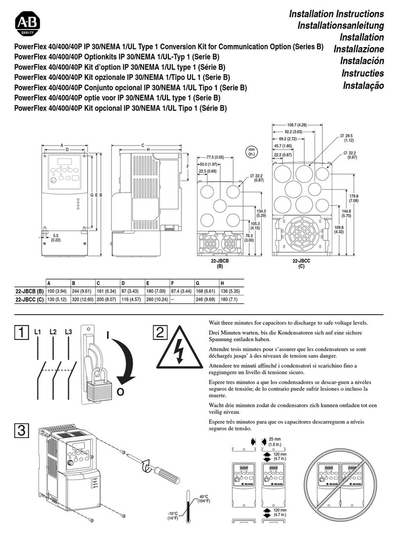
198E-C0S..
Pilot Light (Run)
Green
Pilot Light (Failure)
red
START / STOP
Push Buttons
RESET
Push Button
Options
1
Rockwell Automation maintains current product environmental information on its website at
http://www.rockwellautomation.com/rockwellautomation/about-us/sustainability-ethics/product-environmental-compliance.page
198E-A0S4 / -C0S4 with START / STOP Push Buttons
12
3
45
198E-A0S1 / -C0S1 with RESET Push Button
Accessories
140-L...
(Not for UL or CSA applications)
800FD-P...
198E-PLA
USA + Canada:
(Use 800F Pilot Lights only)
• Push button latch for maintained control
• Drucktasten-Verklinkung für
Dauerkontakt-Steuerung
• Accrochage des bouton-poussoirs pour
commande de contact permanent
• Ritenuta di pulsante per comando a
contatto permanente
• Retención de pulsador para mando a
contacto permanente
198E-PLA:
Replace connection module
Verbindungsmodul austauschen
Remplacer le module de connexion
Sostituire il modulo di collegamento
Reemplace el módulo de conexión
198E-PNT
• Neutral Terminal
• Neutralleiterklemme
• Borne de neutre
• Morsetto di neutro
• Borna de neutro
• Pilot Lights
• Meldeleuchten
• Voyants lumineux
• Lampade spia
• Lámparas de señalización
• Pilot Lights
• Meldeleuchten
• Voyants lumineux
• Lampade spia
• Lámparas de señalización
IMPORTANT NOTICE:
- In case of a separate control voltage circuit place the included warning label
in the appropriate language on the front of the enclosure.
- Bei separater Steuerspannung ist das mitgelieferte Warnschild in der passenden
Sprache auf der Frontseite des Gehäuses anzubringen.
- En cas d'une tension de commande séparée, placer l'étiquette d'avertissement
incluse, dans la langue appropriée, sur la face du boîtier.
- In caso di tensione di di controllo separata posizionare l'etichetta d'avvertimento
inclusa, nella lingua appropriata sulla parte anteriore della custodia.
- En caso de una tensión de circuito de control separado, colocar la etiqueta de
advertencia incluido en el idioma adecuado en la parte frontal del cofre.
2
0
I
Option Emergency Stop (with impulse control only)
Option mechanical latch 198E-PLA for maintained control
Not wired when mechanical latch 198E-PLA is installed
Option trip indicating pilot light

I
0
R
198E-0S4
with START/STOP
Push Buttons
198E-0-S1
Remote Control
(maintained)
WARNING: The opening of the branch circuit protective device
may be an indication that a fault current has been interrupted.
To reduce the risk of fire or electric shock, current-carrying parts
and other components of the controller should be examined and
replaced if damaged.
WARNING: With the mechanical latch () installed or when
wired for 2-wire control, a motor connected to the circuit may
start automatically when the overload relay is in the automatic
reset position.
198E-0-S1
Remote Control
(instantaneous cont.)
3-phase 2-phase Single-phase
R
R
198E-0-S1
MAN-0-AUTO
selector switch



cUL-US Listed Type 12K / 4 / 4X Enclosure
LISTED A191
IND CONT. EQ.
198E-C0S...
SUPPLY CONDUCTOR
SIZE (AWG)
BONDING CONDUCTOR
QTY. SIZE
14 1 14
12 1 12
10 2 12
FOR USE WITH ALLEN-BRADLEY
GROUNDING ADAPTER KIT, CAT. NO. 198-GR1
SEE APPLICABLE CODES AND LAW
FOR GROUNDING REQUIREMENTS
WARNING:
Bonding between metallic
conduits must be provided.
AVERTISSEMENT:
Une liaison électrique doit
être assurée entre les
conduits métalliques.
Wiring Diagrams
Dimensions mm [in.]
3
205
[8.08]
44.5
[1.75]
19.5
[0.77]
188
[7.41]
Ø5.3
[Ø0.21]
51
[2.01]
Ø20.3
[Ø0.80]
23.7
[0.94]
188 mm Ø 5.3
7.4" 0.2" DIA
188
[7.41]
23.8
[0.94]
31.5
[1.24]
25.2
[0.99]
111
[4.37]
5.5
[0.22]
Ø25.3
[Ø1.00]
111
[4.37]
5.5
[0.22]
207.9
[8.19]
97.9
[3.86]
68
[2.68]
60.3
[2.38]
36.5
[1.44]
36.5
[1.44]
Center Marks Inside
Pilot Lights: - 140-L*: IP 54
- 800FD: IP 66
10
2 x 1...6 mm²
2 x No. 14...10 AWG
Pozidriv No. 2
2.3 Nm
20 lb-in
Pozidriv No. 2
2.0 Nm
18 lb-in
(1.2 x 6.5)
Component Selection for Enclosed Starters
3-phase Motors
Single-phase Motors
Artwork 10000389627 / 02. 2015 / Version 3 Copyright ©2015 Rockwell Automation. Technical changes reserved.
230V 50Hz 400V 50Hz 500V 50Hz 690V 50Hz 200V 60Hz 230V 60Hz 460V 60Hz 575V 60Hz 100kA, 690V 100kA, 600V
Contactor
1)
Overload
Relay
2)
Min
A
Max
AkW kW kW kW HP HP HP HP
DIN Fuses
Type gL/gG
Max. Fuse
Class CC, J
100-C09*10 193-ED1AB 0.10 0.50 0.06…0.09 0.06...0.12 0.06...0.12 0.06...0.18 -- -- -- -- 23
100-C09*10 193-ED1BB 0.20 1.0 0.12 0.18...0.25 0.18…0.37 0.25…0.55 -- -- 1/4…1/3 1/4...'1/2 44
100-C09*10 193-ED1CB 1.0 5.0 0.18…1.1 0.37…1.5 0.55…2.2 0.75…3 1/4…3/4 1/4…1 1/2...2 3/4…3 16 10
100-C09*10 193-ED1DB 3.2 16 1.5…3 2.2…4 3.0…4 4 1…2 1 1/2...2 3…5 5...7 1/2 20 15
100-C12*10 193-ED1DB 3.2 16 4 5.5 5.5 5.5 3 3 7 1/2 10 25 20
100-C16*10 193-ED1DB 3.2 16 7.5 7.5 7.5 33
7 1/2 10 32 30
100-C16*10 193-ED1EB 5.7 27 5.5 5 5 10 15 35 45
100-C23*10 193-ED1EB 5.7 27 7.5 10…11 10…13 10 57 1/2 15 15 40 45
100-C09*10 193-T1AA16 0.10 0.16 0.06 -- -- -- -- 21
100-C09*10 193-T1AA25 0.16 0.25 0.06 0.06 0.09 -- -- -- -- 21
100-C09*10 193-T1AA40 0.25 0.40 0.09 0.09...0.12 0.12…0.18 -- -- -- -- 21
100-C09*10 193-T1AA50 0.35 0.50 0.06 0.12 -- -- -- -- 42
100-C09*10 193-T1AA63 0.45 0.63 0.09 0.18 0.25 -- -- -- 1/4 43
100-C09*10 193-T1AA80 0.55 0.80 0.12 0.18 0.25 0.37 -- -- 1/4…1/3 1/3 43
100-C09*10 193-T1AB10 0.75 1.00 0.25 0.37 0.55 -- -- 1/3 1/2 64
100-C09*10 193-T1AB13 0.90 1.30 0.18 0.37 0.75 -- 1/4 1/2 64
100-C09*10 193-T1AB16 1.10 1.6 0.25 0.55 1/4 1/3 3/4 3/4 64
100-C09*10 193-T1AB20 1.40 2.0 0.75 0.75 1.1 1/3 1/3 3/4...1 1 64
100-C09*10 193-T1AB25 1.80 2.5 0.37 1.1 1.5 1/2 1 1/2 10 6
100-C09*10 193-T1AB32 2.3 3.2 0.55 1.1 1.5 2.2 1/2 3/4 1 1/2 2 10 6
100-C09*10 193-T1AB40 2.9 4.0 0.75 1.5 3/4 3/4 2 310 10
100-C09*10 193-T1AB48 3.5 4.8 2.2 3 1 1 3 3 10 10
100-C09*10 193-T1AB63 4.5 6.3 1.1 2.2 3 4 1 1/2 1 1/2 516 12
100-C09*10 193-T1AB75 5.5 7.5 1.5 3 4 1 1/2…2 2 5 5 16 15
100-C09*10 193-T1AC10 7.2 10.0 2.2 4 27 1/2 20 20
100-C09*10 193-T1AC12 9.00 12.5 3 25 20
100-C12*10 193-T1AB75 5.5 7.5 5.5 16 15
100-C12*10 193-T1AC10 7.2 10.0 5.5 20 20
100-C12*10 193-T1AC12 9.00 12.5 5.5 3 3 7 1/2 10 25 20
100-C16*10 193-T1AC10 7.2 10.0 7.5 20 20
100-C16*10 193-T1AC12 9.00 12.5 7.5 25 20
100-C16*10 193-T1AC16 11.3 16.0 4 7.5 7.5 5 10 32 30
100-C16*10 193-T1AC20 15.0 20.0 5 15 32 30
100-C23*10 193-T1AC16 11.3 16.0 10 32 30
100-C23*10 193-T1AC20 15.0 20.0 11 40 35
100-C23*10 193-T1AC21 17.50 21.5 5.5 13 15 40 35
100-C23*10 193-T1AC25 21.00 25.0 11 7 1/2 40 40
230V 50Hz 115V 60Hz 200V 60Hz 230V 60Hz 100kA, 690V 100kA, 600V
Contactor
1)
Overload
Relay
2)
Min
A
Max
AkW HP HP HP
DIN Fuses
Type gL/gG
Max. Fuse
Class CC, J
100-C09*10 193S-EEPB 1.0 5.0 0.12…0.55 1/10…1/6 1/6…1/3 1/6…1/3 16 10
100-C09*10 193S-EERB 3.2 16 0.75…1.5 1/4…1/2 1/2…1 1/2 1/2…1 1/2 20 20
100-C12*10 193S-EERB 3.2 16 2.2 1/2 22
25 25
100-C16*10 193S-EERB 3.2 16 2.2 3/4 22
32 25
100-C16*10 193S-EESB 5.4 27 3.0 1 2335 30
100-C23*10 193S-EESB 5.4 27 4.0 1 1/2...2 3 340 40
100-C09*10 193-T1AA16 0.10 0.16 -- -- -- -- 21
100-C09*10 193-T1AA25 0.16 0.25 -- -- -- -- 21
100-C09*10 193-T1AA40 0.25 0.40 -- -- -- -- 21
100-C09*10 193-T1AA50 0.35 0.50 -- -- -- -- 42
100-C09*10 193-T1AA63 0.45 0.63 -- -- -- -- 43
100-C09*10 193-T1AA80 0.55 0.80 0.06 -- -- -- 43
100-C09*10 193-T1AB10 0.75 1.0 0.09 -- -- -- 64
100-C09*10 193-T1AB13 0.90 1.3 0.12 -- -- -- 64
100-C09*10 193-T1AB16 1.1 1.6 0.12 -- -- -- 66
100-C09*10 193-T1AB20 1.4 2.0 0.18 -- -- -- 66
100-C09*10 193-T1AB25 1.8 2.5 0.25 -- -- 1/6 10 10
100-C09*10 193-T1AB32 2.3 3.2 0.37 1/10 1/6 1/4 10 10
100-C09*10 193-T1AB40 2.9 4.0 0.37 1/8 1/4 1/3 10 10
100-C09*10 193-T1AB48 3.5 4.8 0.55 1/6 1/3 1/3 10 10
100-C09*10 193-T1AB63 4.5 6.3 0.75 1/4 1/2 1/2 16 15
100-C09*10 193-T1AB75 5.5 7.5 1.1 1/3 3/4 16 15
100-C09*10 193-T1AC10 7.2 10.0 1.1 1/3 3/4…1 1 20 20
100-C09*10 193-T1AC12 9.0 12.5 1.5 1/2 1 1/2 1 1/2 25 20
100-C16*10 193-T1AC16 11.3 16.0 2.2 3/4 2 2 32 30
100-C16*10 193-T1AC20 15.0 20.0 3 1 3 32 30
100-C23*10 193-T1AC21 17.5 21.5 31 1/2 3 40 35
100-C23*10 193-T1AC25 21.0 25.0 2 40 35
Components
Current Range
Components
Current Range
1)
Contactors
To complete the Catalog No.,
replace * by the coil voltage code
2)
Overload Relays
193-ED1*: Electronic overload relays
(193-EE* can be used as well).
193S-EE*: Electronic overload relays
specially for single-phase motors
Max. environmental temperature 40 °C
(outside the enclosure)
193-T1*: Thermal overload relays.
Max. environmental temperature 40 °C
(outside the enclosure)
This manual suits for next models

1

Other Allen-Bradley Enclosure manuals

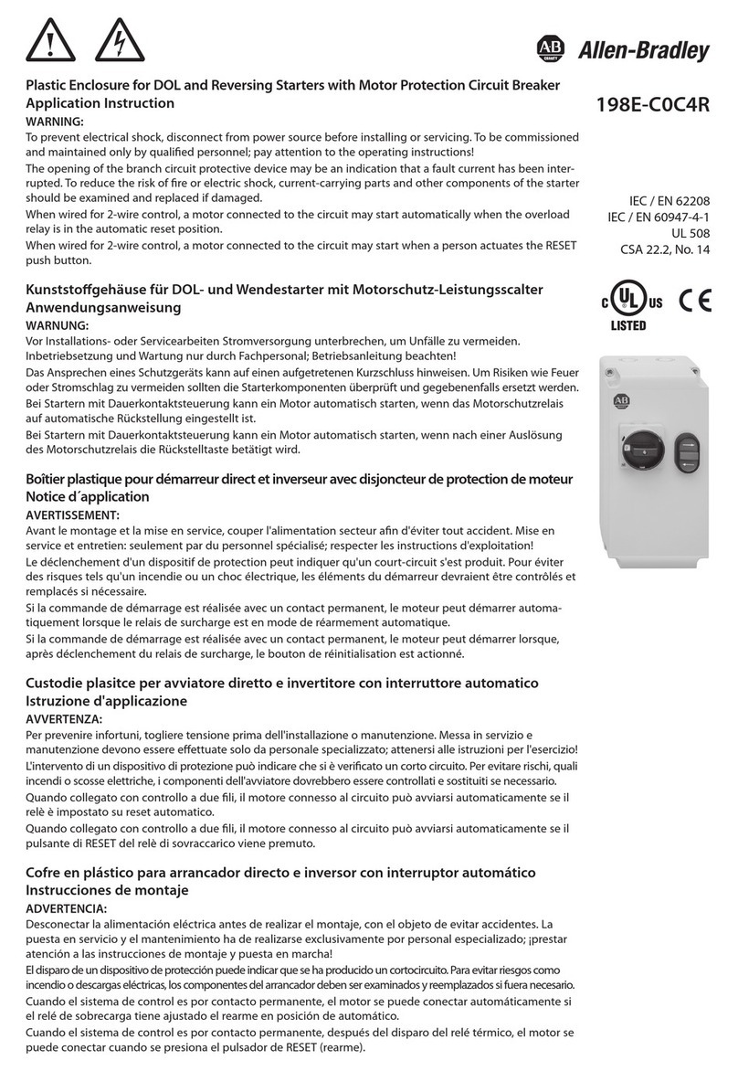
Allen-Bradley 198E-C0C4R User guide

Allen-Bradley

Allen-Bradley 198E-C0C4R User guide

Allen-Bradley CENTERLINE 200 A User manual

Allen-Bradley

Allen-Bradley CENTERLINE 200 A User manual

Allen-Bradley 22-JBCB User manual

Allen-Bradley

Allen-Bradley 22-JBCB User manual

Allen-Bradley SK-M1-CVR0-B4 User manual

Allen-Bradley

Allen-Bradley SK-M1-CVR0-B4 User manual

Allen-Bradley 1336 PLUS II User manual

Allen-Bradley

Allen-Bradley 1336 PLUS II User manual

Allen-Bradley PowerFlex Active Front End User manual

Allen-Bradley

Allen-Bradley PowerFlex Active Front End User manual

Allen-Bradley 198E-A0S Series User guide

Allen-Bradley

Allen-Bradley 198E-A0S Series User guide

Allen-Bradley 198E-C0S4R User guide

Allen-Bradley

Allen-Bradley 198E-C0S4R User guide

Popular Enclosure manuals by other brands

OWC Mercury Pro Assembly manual & user guide

OWC

OWC Mercury Pro Assembly manual & user guide

Labconco XPert 38872 Series user manual

Labconco

Labconco XPert 38872 Series user manual

Fusion R800RAID user guide

Fusion

Fusion R800RAID user guide

Hartke 210TP owner's manual

Hartke

Hartke 210TP owner's manual

Conrad 41 77 98 operating instructions

Conrad

Conrad 41 77 98 operating instructions

Lindy 42714 user manual

Lindy

Lindy 42714 user manual

StarTech.com SAT5210U2E instruction manual

StarTech.com

StarTech.com SAT5210U2E instruction manual

peerless-AV KIL640 manual

peerless-AV

peerless-AV KIL640 manual

CRU RAX211-3QR manual

CRU

CRU RAX211-3QR manual

Geeek A40 installation guide

Geeek

Geeek A40 installation guide

SMS C5-21U005-2-A Installation and adjustment manual

SMS

SMS C5-21U005-2-A Installation and adjustment manual

Kicker SKM10 owner's manual

Kicker

Kicker SKM10 owner's manual

Origen ae S10V user guide

Origen ae

Origen ae S10V user guide

Macpower & Tytech DaisyCutter User manual & installation guide

Macpower & Tytech

Macpower & Tytech DaisyCutter User manual & installation guide

Kaman SERIES 8000 Reference manual

Kaman

Kaman SERIES 8000 Reference manual

StorCase Technology Data Express DE110 user guide

StorCase Technology

StorCase Technology Data Express DE110 user guide

Lightolier ULM module motion installation instructions

Lightolier

Lightolier ULM module motion installation instructions

OWC Mercury Elite Pro Dual Assembly manual & user guide

OWC

OWC Mercury Elite Pro Dual Assembly manual & user guide

manuals.online logo
manuals.online logoBrands
  • About & Mission
  • Contact us
  • Privacy Policy
  • Terms and Conditions

Copyright 2025 Manuals.Online. All Rights Reserved.