Southwire 41151S User manual

Operating Instructions
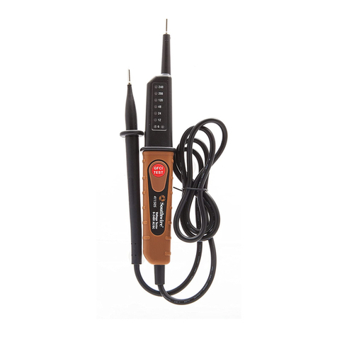
41151S Voltage Tester
southwiretools.com
1-855-SW-T00LS
Toll Free Technical Help
Assistance technique gratuite
Línea de Ayuda Técnica Gratuita
41151S manual/manuel
Contents Made in China/Fabriqué en Chine
Product distributed by/Produit distribué par
Southwire Company, LLC.
One Southwire Drive, Carrollton, GA 30119
©2018 Southwire Company, LLC.
All rights reserved. Tous droits réservés.
02/19

2
Introduction
1
WARNINGS
The Southwire 41151S Compact Voltage and GFCI Tester is a
simple and safe way to measure voltage, test for live circuits, and
test the functionality of Ground Fault Circuit Interrupter (GFCI)
circuits. This pocket tester tests AC voltage up to 480V and DC
voltage up to 110V. It’s small enough to comfortably fit in your
pocket as the test probes can be stored on the back of the tester
where they won’t catch on clothing. The 41151S is fully tested and
UL listed and with proper use, will provide many years of reliable
service.
Warnings
Comply with all safety codes. Use approved personal protective
equipment when working near live electrical circuits - particularly
with regard to arc-flash potential
instructions in this manual before using this tester.
accordance to the manufacturer’s instructions.
measurements.
the circuit under test.
equipment when working near live electrical circuits - particularly
with regard to arc-flash potential.
peak, or 60V DC pose a shock hazard.
compromised.
voltage.
electrical storms.
rated input limit.

4
General Specifications
Insulation
Display
Operating Temperature
StorageTemperature
Relative Humidity
Operating Altitude
Weight
Dimensions:
Safety:
Ingress Protection
Class 2, Double insulation.
LED
32°F to 104°F (0°C to 40°C)
5°F to 131°F (-15°C to 55°C)
Maximum, non-condensing: 85%
0-2000 meters
0.2 pounds (90.7grams)
5.5” x 1.7” x 1.1” (140mm x 43mm x 28)
UL: 61010 - 1:2012, 61010-2-030: 2012,
61010-2-033: 2014
EMC:EN61326-1:2013, EN61326-2-2:2013
IP42
3
International SafetySymbols
Potential danger. Indicatesthe user must refer to the manual for important
safety information.
Indicates hazardousvoltagesmay be present
Equipment is protectedby double or reinforced insulation.
Indicatesthe terminal(s) so markedmust not be connected to a circuit where the
voltage with respect to earth ground exceeds the maximum safety rating of the
meter.
Indicatesthe terminal(s) so markedmay be subjected to hazardous voltages.
MAX
600V
The measurement category (CAT) rating andvoltage rating is determined by a
combination of the tester andthe test probes. The combinationrating is the
LOWEST rating of any individual component.
Brief Description Typical Applications
Category
Rating
Single phase receptacles
andconnectedloads
Three phase circuits
andsingle phase
lighting circuits in
commercial buildings
III
switchgear and distribution panels
III
soruce
CAT II
CAT III
Safety Category Ratings
AWARNING:
Input Limits
Function Maximum Input
Voltage AC or DC
from one or both test probes. Refer to Input Limitssectionof this manualfor maximum
voltage ratings.

6
Maintenance
5
the following care instructions are performed:
Temperature extremes can shorten the life of the electronicparts and
distort or melt plastic parts.
damage the electronic parts or the case.
damp cloth. DO NOT use chemicals, cleaning solvents, or detergents.
PRODUCT COMPLIANCE
Users of this product are cautioned not to make modifications or changes
that are not approvedby Southwire Company, LLC. Doing so may void the
compliance of thisproduct with applicable laws and regulatory require-
ments andmay result in the loss of the user’sauthority to operate the
equipment.
UNITED STATES ANDCANADA
This device complies withPart 15of the FCC Rules. Operation is subject to
the following two conditions; (1) This device may not cause harmful
interference, and (2)this device must accept any interference received,
including interference that may cause undesiredoperation.
This equipment hasbeen tested and found to comply withthe limitsfor a
Class B digital device, pursuant to Part 15 of the FCCRules. These limits
are designed to provide reasonable protection against harmful interference
in a residential installation. This equipment generates usesand canradiate
radio frequency energy and, if not installed and used in accordance with the
instructions, may cause harmful interference to radio communications.
particular installation. If this equipment does cause harmful interference to
radio or television reception, which can be determined by turning the
equipment off and on, the user isencouragedto try to correct the interfer-
ence by one or more of the following measures:
which the radio or televisionreceiver is connected.
CAUTION: To comply with the limits of the Class B device, pursuant to Part
15 of the FCC Rules, this device is to comply with Class B limits. All peripherals
must be shielded andgrounded. Operation with non-certified peripherals or
non-shielded cables islikely to result ininterference and reception of the device.
Canadian Digital Apparatus Compliance
EUROPEAN UNION
In accordance with CE requirements, the Declarationof Conformity may be
found at www.southwiretools.com

AC and DC Voltage Indicators
87
Meter Description
1. Test LeadStorage Position1–Probe tips spaced for insertion into ACoutlet
2. Test LeadStorage Position2–Probe tips concealed for pocket storage
FRONT VIEW
REAR VIEW
measuring AC or DC voltage. Inaddition, if you are measuringDCvoltage,
the two indicators showwhether the polarity ispositive or negative. See
illustrationbelow.
When both LED indicators are illuminated, the voltage tester ismeasuring
AC voltage andyou shoulduse the AC voltage scale onthe left side of the
When only one LED indicator isilluminated, the voltage tester is measur-
ing DCvoltage. If only the “+ “or positive LED isilluminated, the polarity
is DC +. If the “- “or negative LED isilluminated, the polarity is DC -.
When both LED indicators
are illuminated, you are
measuring AC voltage.
Use the AC voltage scale
on the left.
The above diagram is
When one LED indicators
is illuminated, you are
measuring DC voltage.
Use the DC voltage scale
on the right.
The above diagram is
positive polarity
When one LED indicators
is illuminated, you are
measuring DC voltage.
Use the DC voltage scale
on the right.
The above diagram is
negative polarity
7
1
3
2
4
5
6

AC Voltage Measurements
910
Observe all safety precautions when working on live
voltages.
Warning:
The tester is showing
that approximately
measured When both LED indicators are
illuminated, AC voltage is being
measured
1. Touch the test probes in parallel to the circuit under test.
2. When the tester ismeasuring AC voltage, both AC voltage indicators
will be illuminated.
3. The top of the tester is marked AC onthe left and DC onthe right.
When the AC voltage indicators are illuminated, use the AC voltage scale
increments.
4. The approximate ACvoltage is the number onthe AC voltage scale that
corresponds to the top-most LEDthat isilluminated.
5. When the voltage tester first detectsvoltage, it may pause briefly at
normal operation.
6. In the figure below, both LED voltage indicatorsare illuminated

DC Voltage MeasurementsDC Voltage Measurements
11 12
When one LED indicator is
illuminated, DC voltage is
being measured
The tester is showing
that approximately
measured
Observe all safety precautions when working on live
voltages.
Warning:
1. For DC measurements, touch the redtest probe to the positive side of
the circuit and the black test probe to the negative side of the circuit.
2. When measuring DCvoltage, only one voltage indicator will be
illuminated. If the redtest probe is touching the positive side of the
circuit and the black test probe istouching the negative side of the
circuit, then the “+ “or positive DC voltage indicator will be illuminated.
If the redtest probe istouching the negative side of the circuit andthe
black test probe istouching the positive side of the circuit, then the “–
“or negative DC voltage indicator will be illuminated.
3. The topof the tester ismarked AConthe left and DC onthe right.
When measuring DCvoltage, use the DC voltage scale onthe right side
increments.
4. The approximate DCvoltage isthe number onthe DC voltage scale
that corresponds to the top-most LED that is illuminated.
5. In the figure below, the “+” or positive voltage indicator is illuminated
whereas the “- “or negative voltage indicator is not illuminated. This
signifies that the voltage tester is measuring DCvoltage. Inaddition,

14
13
Test GFCI
Specifications
wired properly
circuit has been tripped.
testing.
outlets)
Test GFCI
proceeding.
receptacle or breaker does trip, reset before proceeding.
5. If the outlet is a Tamper Resistant (TR) design, you may be prevented from
NEUTRAL AC: 12, 24, 48, 120, 240, 480
DC: 9, 12, 24, 36, 48, 110
AC Frequency Range 50Hz - 60Hz
Opera ng Temperature 32 °F to 104 °F (-0 °C to 40°C)
Storage Temperature 5°F to 131 °F (-15°C to 55°C)
Rela ve Humidity Max 85% RH (NC)
Al tude 6560 feet (2000m)
Drop Protec on 6.5 feet (2 meters)
Ingress Protec on IP42
Safety Ra ng CAT III 600V
Voltage LED Steps

15 16
Register YourVoltage Tester
-
on Register Product to register your product.
REGISTER YOUR PRODUCT
Register your product purchase at www.southwiretools.com. At
Southwire, we provide you with the best customer experience. Simply
provide your model number, serial number, and just a few pieces of
information about yourself - it is that quick and easy.
“third hand”. This allows you to hold one test lead and the multimeter in
one hand while you touch measurement points with the other test lead.
Test Lead Storage
For technical questions related to your multimeter or information on how to
purchase fuses or Southwire accessories, contact Southwire Customer
Service at 1-855-SW-TOOLS
Customer Service
LIMITED WARRANTY AND LIMITATION OF LIABILITY ON
SOUTHWIRE METERS & TESTERS
Southwire Company, LLC
Attention: ToolWarranty Return
840 Old Bremen Road
Carrollton, GA 30117
Southwire Company, LLC warrants this product to be free fromdefects in
material and workmanship forfive years from the date of purchase. This
warranty does not coverfuses, disposable batteries, ordamage arising from an
accident, neglect, misapplication, contamination,modification, improper
maintenance or repair, operation outside of specifications, orabnormal
repair or replacement of the product. Whether Southwire repairs or replaces the
product will be a determinationthat Southwire makes at itssole discretion.
relating to this product, and no such reseller warranty will be binding on
Southwire. If you have a warranty claim, orif the product needs to be serviced
during or afterthe warranty period set forth above, please contact the
Customer Service Department at 855-SWTOOLS (855-798-6657). The sender
is responsible forall shipping, freight, insurance, and packaging costs
associated with sending a product to Southwire. Southwire will not be
responsible forlost ordamaged products returned pursuant to this warranty.
All products returned to Southwire underthis warranty should be mailed to:

Instrucciones de operación
Probador de voltaje 41151S
southwiretools.com
1-855-SW-T00LS
Toll Free Technical Help
Assistance technique gratuite
Línea de Ayuda Técnica Gratuita
41151S manual/manuel
Contents Made in China/Fabriqué en Chine
Product distributed by/Produit distribué par
Southwire Company, LLC.
One Southwire Drive, Carrollton, GA 30119
©2018 Southwire Company, LLC.
All rights reserved. Tous droits réservés.
02/19

2
Introduction
1
ADVERTENCIAS
El probador de voltaje y GFCI compacto Southwire 41151S es una
forma simple y segura de medir el voltaje y probar circuitos activos
y la funcionalidad de los circuitos del interruptor de circuito de falla
a tierra (GFCI). Este probador de bolsillo prueba el voltaje de CA
hasta 480 V y el voltaje de CC hasta 110 V. Es lo suficientemente
pequeño como para caber cómodamente en su bolsillo, ya que las
sondas de prueba se pueden almacenar en la parte posterior del
probador, donde no se engancharán en la ropa. El 41151S está
completamente probado y aprobados por UL y, con el uso adecua-
do, proporcionará muchos años de servicio confiable.
Advertencias
Cumpla con todos los códigos de seguridad. Use equipo de
protección personal aprobado cuando trabaje cerca de circuitos
eléctricos energizados, particularmente con respecto al potencial
de arco eléctrico.
Límites de entrada
Función Entrada máxima
Voltaje de CAoCCCA 480 V / CC 110 V
-
ciones de operación de este manual antes de utilizar este
probador.
proteger al usuario si no se usa de acuerdo con las instrucciones
del fabricante.
sondas cuando realice mediciones.
cables de prueba del circuito que se esté probando.
protección personal aprobado cuando trabaje cerca de circuitos
eléctricos energizados, particularmente con respecto al potencial
de arco eléctrico.
desnudos o barras colectoras o cerca de ellos.
VCC presentan un riesgo de descarga eléctrica.
parece estar dañado.
puede estar en riesgo.
un voltaje activo conocido.
durante tormentas eléctricas.
-
sivos.

Especificaciones generales
4
5.5” x 1.7” x 1.1” (140 mm x 43 mm x 28)
UL: 61010 - 1:2012, 61010-2-030: 2012,
61010-2-033: 2014
EMC:EN61326-1:2013, EN61326-2-2:2013
3
Símbolos internacionales de seguridad
Peligro potencial. Indica que el usuario debe consultar el manual para obtener
información de seguridad importante.
Indica que pueden existir voltajes peligrosos.
El equipo está protegido por aislamiento doble o reforzado.
Indica que las terminales así marcadas no deben conectarse a uncircuito
donde elvoltaje con respecto a la conexión a tierra es superior al máximo
indicado por la clasificación de seguridad del medidor.
Indica que las terminales así marcadas pueden estar sujetas
a voltajes peligrosos.
MAX
600V
La clasificación de la categoría de medición (CAT) y la clasificación de voltaje
están determinadaspor una combinación del probador y las sondas de prueba.
La potencia de la combinación es la MÁS BAJA de cualquier componente
individual.
Breve descripción Aplicaciones típicas
Categoría
Clasificación
Receptáculos
monofásicos y cargas
conectadas
Circuitostrifásicos y
circuitos de iluminación
monofásicos en edificios
comerciales
tableros de distribución y paneles de distribución
de una fuente de Cat III
Cat II
Cat III
Calificaciones de categoría de seguridad
ADVERTENCIA:
El funcionamiento está limitado a las aplicacionesde la CAT II 600 V cuando las
puntasaisladasse retiran de una o ambas sondasde prueba. Consulte las
clasificaciones de voltaje máximo enla sección Límites de entrada de este manual.
Cuando se usa la punta aislada, los cables de prueba son CATIII 600 V
Cuando no se usa la punta aislada, los cables de prueba sonCATII 600V
IP42
Máxima, sin condensación: 85 %
0-2000 metros
0.2 libras (90.7 gramos)
5°F a 131°F (-15°C a 55°C)
32°F a 104°F (0°C a 40°C)
LED
Humedad relativa
Altitud de operación
Peso
Dimensiones:
Seguridad:
Protecciónde ingreso
Aislamiento
Exhibición
Temperatura de
operación
Temperatura de
almacenamiento
Clase 2, aislamiento doble

6
Mantenimiento
5
servicio confiable si se llevan a cabo las siguientes instrucciones de
cuidado.
piezaselectrónicas y distorsionar o fundir las piezasde plástico.
-
limpieza o detergentes.
CUMPLIMIENTO DEL PRODUCTO
Se advierte a los usuarios de este producto que no realicen modificaciones
puede anular el cumplimiento de este producto con los requisitos aplicables
equipo.
Este dispositivo cumple con la Sección 15 de las reglas de la FCC. El
funcionamiento está sujeto a las dos condiciones siguientes: (1) este
cualquier interferencia recibida, incluso aquellas que puedan provocar
digital de Clase B, de acuerdo con la Sección 15 de las Reglas de la FCC.
genera, utiliza y puede irradiar energía de radiofrecuencia y, sino se instala
produzcaninterferencias en una instalaciónenparticular. En caso de que
radio o televisión, lo que se puede determinar alapagar y encender el
equipo, se recomienda al usuario que intente corregir la interferencia
aplicando una o más de las siguientesmedidas:
está conectado elreceptor.
PRECAUCIÓN: Para cumplir con los límites para dispositivos de Clase B,
no certificados o con cables no blindados puede provocar interferenciasen la
Cumplimiento de aparatosdigitales canadienses
CAN ICES-3(B)/NMB-3(B)
De acuerdo con los requisitosde CE, la Declaraciónde conformidad se puede
encontrar en www.southwiretools.com

Indicadores de voltaje de CAydeCC
87
Descripción del medidor
1. IndicadoresLED de nivelde voltaje (6en total)
2. Escala de voltaje de CA
(12 V, 24 V, 48 V, 120 V, 240 V, 480 V)
3. Escala de voltaje de CC
(9 V, 12 V, 24 V, 36V, 48V, 110 V)
4. Indicadoresde voltaje de CA
5. Indicadoresde voltaje y polaridad de CC
1. Posición 1 de almacenamiento del cable de
prueba: puntas de sonda separadas para insertarlasen la toma de CA
2. Posición 2 de almacenamiento del cable de prueba: puntas
de sonda ocultas para almacenamiento en bolsillo
VISTA FRONTAL
VISTA POSTERIOR
Su medidor de voltaje tiene dos indicadoresLEDque indican siestá
midiendo voltaje de CA o CC. Además, sise está midiendo el voltaje de
CC, los dos indicadores muestran si la polaridad es positiva o negativa.
Vea la siguiente ilustración.
Cuando ambos indicadores LEDestániluminados, el probador de voltaje
está midiendo elvoltaje de CAy debe usar la escala de voltaje de CA en el
lado izquierdo del probador. La escala de voltaje de CAva de 12 V a 480 V
en 6 incrementos.
Cuando solo se ilumina unindicador LED, elprobador de voltaje está
midiendo elvoltaje de CC. Si solo se ilumina el LED "+" o positivo, la
polaridad esCC +. Si solo se ilumina el LED "-" o negativo, la polaridad es
CC -.
Cuando se encienden
ambos indicadores LED,
se está midiendo el
voltaje de CA.
Use la escala de voltaje de
CA situada a la izquierda.
El diagrama de arriba
Cuando se enciende un
indicador LED, se está
midiendo el voltaje de CC.
Use la escala de voltaje de
El diagrama de arriba
muestra 12 voltios de CC
con polaridad positiva.
Cuando se enciende un
indicador LED, se está
midiendo el voltaje de CC.
Use la escala de voltaje
de CC situada a la
arriba muestra 9 voltios
de CC con polaridad
negativa
7
1
3
2
4
5
6

910
1. Ponga las sondas de prueba en contacto paralelo al circuito que se
está probando.
voltaje de CA se iluminarán.
3. La parte superior del probador está marcada como CA a la izquierda y CC
use la escala de voltaje de CAde la izquierda. La escala de voltaje de
CA lee desde 12 V CA a 480 V CA en seis incrementos.
corresponde alLED superior que está iluminado.
5. Cuando elprobador de voltaje detecta voltaje por primera vez, puede
detenerse brevemente enelLED 12V CA / 9 V CC antes de encender los
LEDrestantes. Este funcionamiento es normal.
6. En la siguiente figura, ambos indicadoresLED de voltaje están iluminados,
lo que significa que el probador está midiendo elvoltaje de CA. Además,
los LED de 12 V, 24V, 48V y 120 V están iluminados. Esto significa que
el probador está midiendo aproximadamente 120 V CA.
ADVERTENCIA: tome todas las precauciones de seguridad al
trabajar con voltajes energizados.
Mediciones de voltaje de CA
El probador está
mostrando que
se están midiendo Cuando se encienden ambos
indicadores LED, se está
midiendo el voltaje de CA

positivo del circuito y la sonda de prueba negra con el lado negativo
del circuito.
2. Al medir el voltaje de CC, solo se iluminará un indicador de voltaje.
Si la sonda de prueba roja está tocando el lado positivo del circuito y la
sonda de prueba negra está tocando el lado negativo del circuito, entonces
el indicador de voltaje de CC positivo o "+" se iluminará. Si la sonda de
prueba roja está tocando el lado negativo del circuito y la sonda de prueba
negra está tocando el lado positivo del circuito, entonces se iluminará el
indicador de voltaje de CC negativo o "-".
3. La parte superior del probador está marcada como CA a la izquierda y CC
9 V CC a 110V CC en6incrementos.
corresponde alLED superior que está iluminado.
5. En la siguiente figura, elindicador de voltaje positivo o "+" se ilumina,
mientras que el indicador de voltaje negativo o "-" no se ilumina. Esto
significa que elprobador de voltaje está midiendo elvoltaje de CC. Además,
losLED de 9V y 12V están iluminados. Esto significa que el probador está
midiendo aproximadamente 12 V CC.
Mediciones de voltaje de CC Mediciones de voltaje de CC
tome todas las precauciones de
seguridad altrabajar convoltajes
energizados.
ADVERTENCIA:
11 12
Cuando se enciende un
indicador LED, se está
midiendo el voltaje de CC
El probador está mostrando
que se están midiendo
aproximadamente 12 V CC

14
13
EtapasLEDde distinto voltaje
Rango de frecuencia de CA
Temperatura de operación
Temperatura de almacenamiento
Altitud
Protección contra caídas
Protección de ingreso
Clasificación de seguridad
Mesures de résistance
Especificaciones
6. El probador de voltaje debe indicar 120 V CA si la toma está alimentada
y cableada correctamente
Se apagarán todas las luces LED en el voltímetro, lo que indica que el
electricista cualificado.
prueba.
(tomas sin conexión a tierra)
CA : 12, 24, 48, 120, 240, 480
CC : 9, 12, 24, 36, 48, 110
32 °F a 104 °F (-0 °C a 40 °C)
5 °F a 131 °F (-15 °C a 55 °C)
≤ 6560 pies (2000 m)
6.5 pies (2 metros)
IP42
CAT III DE 600 V
Prueba de GFCI
ADVERTENCIA: Tome todas las precauciones de seguridad al trabajar con
voltajes energizados.
probando antes de continuar.
activarse. Si no se dispara, no use el receptáculo o los receptáculos y consulte
reinicie antes de continuar.
3. Inserte una de las sondas de prueba del probador de voltaje en el lado
4. Inserte la otra sonda de prueba en la abertura de conexión a TIERRA
inserte la sonda de prueba en la abertura CALIENTE.
CALIENTE
A TIERRA

15 16
Registre su probador de voltaje
producto.
REGISTRESUPRODUCTO
Registre la compra de suproducto en www.southwiretools.com. En
usted; es asíde rápido y fácil.
parte posterior del probador. Puede guardar cómodamente los cables de
usar uno de los soportes de los cables de prueba como una "tercera
mano". Esto le permite sostener un cable de prueba y el multímetro en una
mano mientras toca los puntos de medición con el otro cable de prueba.
Almacenamiento de los cables de prueba
Servicio al cliente
GARANTÍA LIMITADA Y LIMITACIÓN DERESPONSABILIDAD
EN MEDIDORES Y PROBADORES DE SOUTHWIRE
Southwire Company, LLC
Atención: devolución de la garantía de la herramienta
840 Old Bremen Road
Carrollton, GA 30117
Southwire Company, LLC garantiza que este producto estará libre de defectos
materialesy de mano de obra durante cinco años a partirde la fecha de
derivadosde un accidente, negligencia, mala aplicación, contaminación,
modificación, mantenimiento o reparacióninadecuados, funcionamiento fuera
-
reemplazo del producto porparte de Southwire. Si Southwire repara o
reemplaza el producto será una determinación que Southwire hace a su
-
revendedor de este tipo será vinculante para Southwire. Si tiene un reclamo
a:

Mode d’emploi
Testeur de tension 41151S
southwiretools.com
1-855-SW-T00LS
Toll Free Technical Help
Assistance technique gratuite
Línea de Ayuda Técnica Gratuita
41151S manual/manuel
Contents Made in China/Fabriqué en Chine
Product distributed by/Produit distribué par
Southwire Company, LLC.
One Southwire Drive, Carrollton, GA 30119
©2018 Southwire Company, LLC.
All rights reserved. Tous droits réservés.
02/19

2
Introduction
1
AVERTISSEMENTS
Le testeur de tension et de GFCI compact Southwire 41151S est un
moyen simple et sûr de mesurer la tension, de tester les circuits
sous tension et de tester la fonctionnalité des circuits de
disjoncteur de fuite à la terre (GFCI). Ce testeur de poche teste la
tension alternative jusqu'à 480 V et la tension continue jusqu'à 110
V. Il est suffisamment petit pour tenir confortablement dans votre
poche, car les sondes de test peuvent être rangées à l'arrière du
testeur, sans risque de se coincer dans les vêtements. Le testeur
41151S a été entièrement testé et homologué UL et dans un cadre
d'utilisation appropriée, il fournira un service fiable pendant de
nombreuses années.
Avertissements
Respectez tous les codes de sécurité. Utilisez un équipement de
protection individuelle approuvé lorsque vous travaillez à proximité
de circuits électriques sous tension – en particulier en ce qui
concerne le risque potentiel d'arc électrique.
Limites d'entrée
Fonction Entrée maximale
Tension alternative
ou continue AC 480 V/DC110 V
de sécurité et les instructions d'utilisation contenues dans ce
manuel avant d'utiliser ce testeur.
l'utilisateur si elles ne sont pas utilisées conformément aux instruc-
tions du fabricant.
des mesures.
toujours les fils d'essai du circuit à tester.
protection individuelle approuvé lorsque vous travaillez à proximité
de circuits électriques sous tension – en particulier en ce qui
concerne le risque potentiel d'arc électrique.
-
teurs nus ou des barres omnibus ou à proximité.
présentent un risque d'électrocution.
-
magés.
protection peut être compromise.
une tension active connue.
trempés ni pendant des orages.
de gaz explosifs.
d'entrée nominale maximale du testeur.
This manual suits for next models
1
Table of contents
Languages:
Other Southwire Test Equipment manuals
Popular Test Equipment manuals by other brands

ACT
ACT GOLD-PLUS operating instructions

PeakTech
PeakTech 1240 Operation manual

Gossen MetraWatt
Gossen MetraWatt PROFITEST PVSUN operating instructions

IEI Technology
IEI Technology GeniSPOT user manual

Agilent Technologies
Agilent Technologies InfiniiVision 7000B Series datasheet

Fluke
Fluke 55XXA instructions