4- [EN] English K405 Issue 3
To start - Prepare the instrument
Before you use the instrument for the first time:
• Make sure that there is no damage to the instrument,
and that there are no missing items.
• Remove the plastic film that protects the display. Use
the tag (◗) in the top right-hand corner.
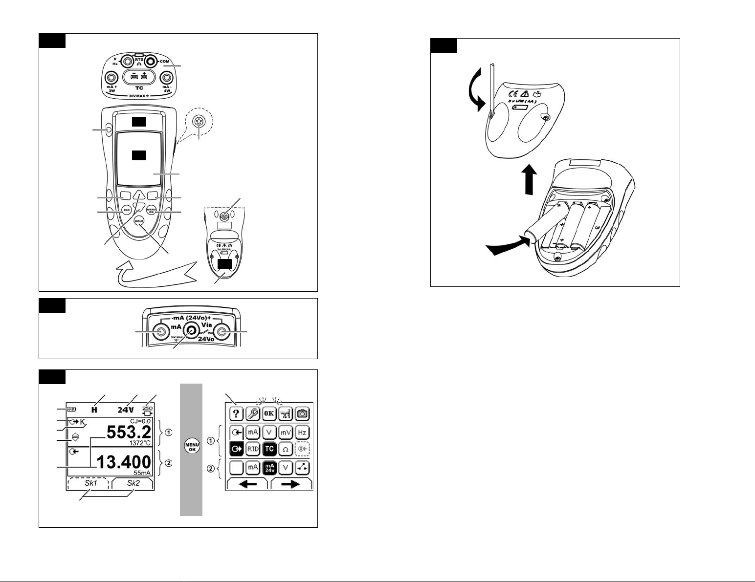
• Install the batteries (refer to B1). Then re-attach the
cover.
To start - Power on or off
To set the power on or off, press ❍(A1 - item 1). The
instrument does a self test and then shows the applicable
data.
When the power is off, the last set of configuration options
stays in memory. Refer to “Maintenance”.
To start - Set up the basic operation
Use the Set Up menu to set up the basic operation of the
instrument.
If there is additional data for a menu option, select
Settings (■■) to see the values that are set up. If
necessary, adjust the values.
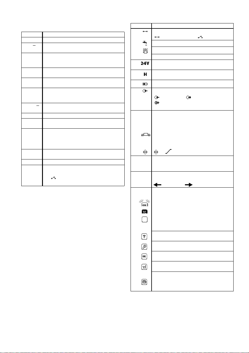
Table 1: Menu options - Set Up
To start - Select a task (Measure and/or supply)
When the instrument is set up (Table 1), use the task
selection menu to select the applicable task.
If you attach a Universal Measurement Module (UMM) to
the communications port (A1 - item 9), the task selection
menu shows the applicable IDOS options.
Make the necessary selections from each area (➀and ➁).
One task is permitted in each area.
Note: Use the Dual Function area (➁) to do two operations
at the same time. If the area ➁selection is not necessary,
set this area to off (■). This saves the battery power.
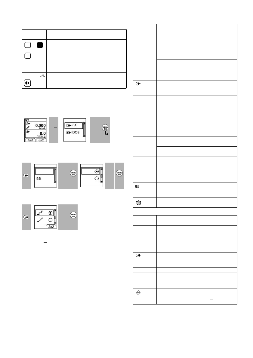
Table 2: Menu options - Task selections (Area ➀)
12
Task selection
menu: 3Menu:
Set Up 45
▲
▼
+
■■
▲
▼
(Table 2) (Table 1) [✓]/[ ]
Options Description
... Scale To select the applicable international temperature
scale: IPTS 68 or ITS 90.
To add a 250Ωseries resistor into the mA circuit.
You can then use this instrument together with a
HART®communicator to set up and calibrate
HART®devices.
To select and set up the backlight facility + timer.
Additional data: Select Settings (■■)
To select and set up the power off facility + timer.
Additional data: Select Settings (■■)
To show the battery level (%).
To set the display contrast (%).
▲ Increases %, ▼ decreases %
To set the time + date. The calibration facility uses
the date to give service and calibration messages.
To set the language option.
To calibrate the instrument.
Additional data: Refer to “Calibration”.
To select and show the applicable status data.
(Software Build, Calibration Due date, Serial
Number, IDOS Information).
1Task selection
menu: 2345
▲
▼
+
■■
▲
▼
+
■■
(Table 2/3) Task = mA output
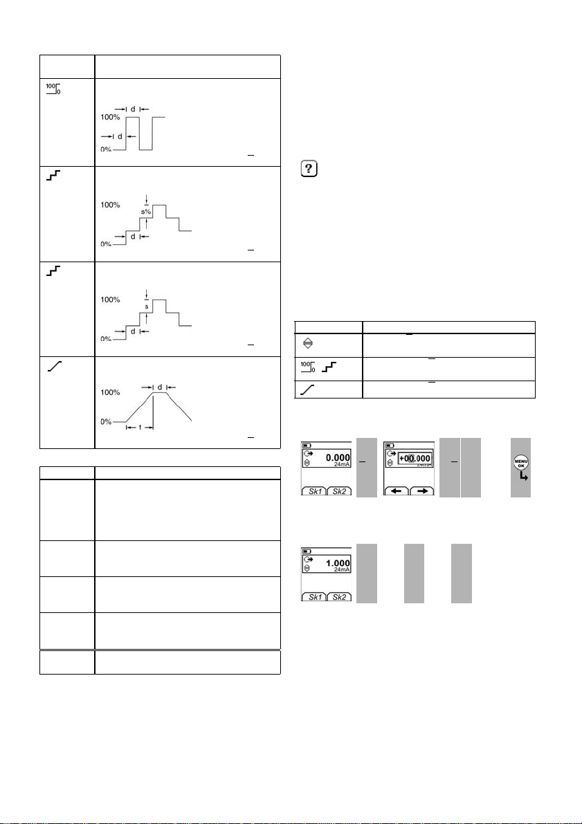
Task selection
menu: 6Display:
mA output
(Table 2/3) Sk1 = Edit
Sk2 = Settings
Options
(If applicable)
Description
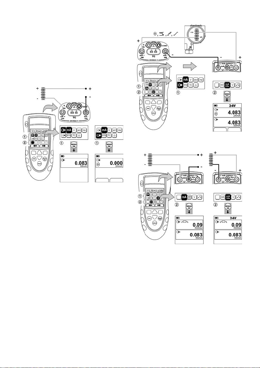
Input measurement tasks:
mA Measure ±55 mA
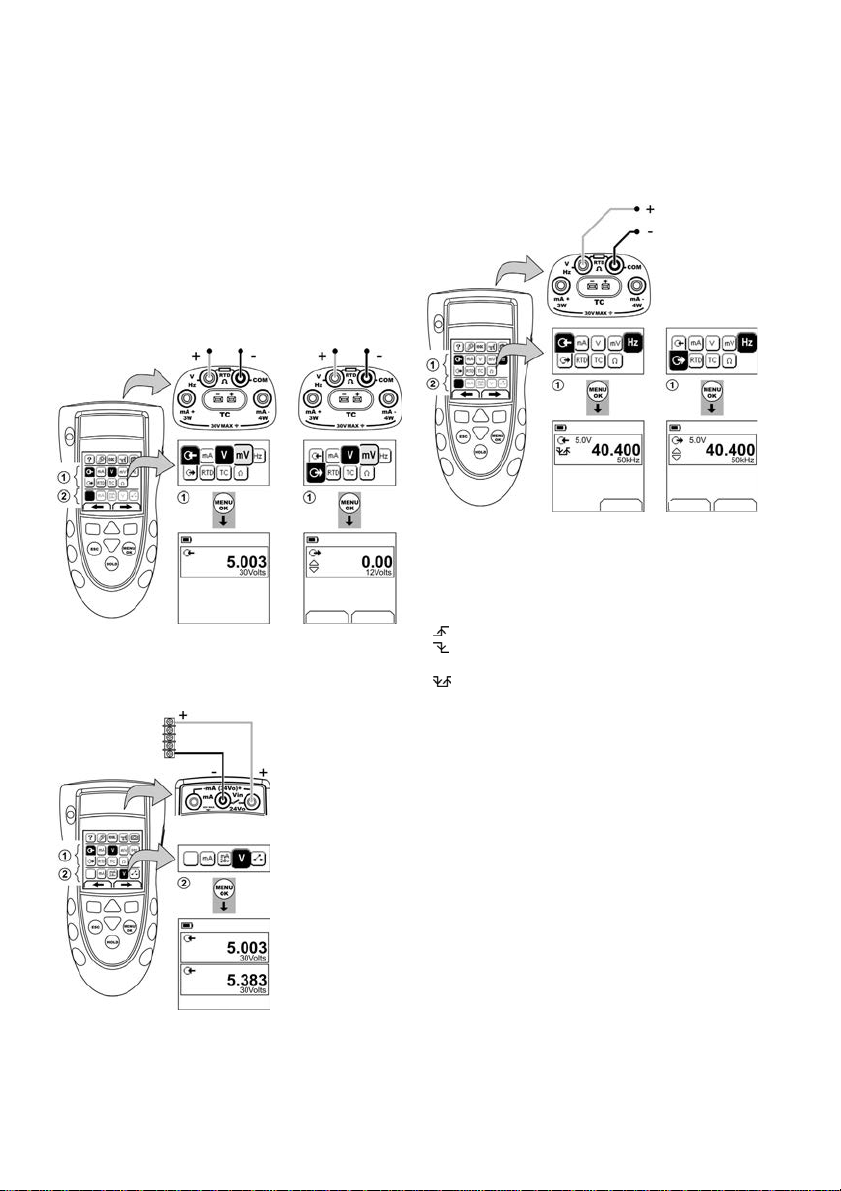
V Measure ±30V
mV Measure ±120mV
Hz Measure the frequency (Units: Table 4)
RTD Measure RTD temperature
ΩMeasure RTD resistance or Ω
TC Measure thermocouple temperature OR mV
Only when an IDOS UMM is attached. An IDOS
measurement task.
Output tasks:
mA Supply 0 to 24 mA
VSupply0to12V
mV Supply 0 to 120mV
Hz Supply an output frequency (Units: Table 4)
RTD Simulate RTD temperature
ΩSimulate RTD resistance or Ω
TC Simulate thermocouple temperature OR mV