Section 2
2 - 1
Winch Operation
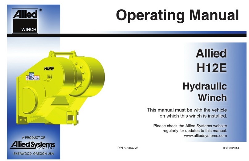
The Allied H12A Winch is made up of these basic as-
semblies:
1. Hydraulic controls and motor
2. Primary drive: motor mount, spring applied/hydrau-
lically released fail-safe brake, primary planetary
reduction
3. Final reduction: 1 or 2 planetary reductions
4. Drum group: winch drum, winch housing, drive
shaft
The main hydraulic hoses from the tractor’s ripper circuit
supply oil to the two-speed motor for LINE-IN and LINE-
OUT functions. Pilot oil pressure is routed through an
electrically operated solenoid. The solenoid directs oil
flow to one of two ports, which then engages either a high
or low motor speed. An electrical switch located on the
operator’s compartment allows the operator to control the
solenoid and, therefore, the winch motor speed.
The hydraulic motor drives the sun gear of the primary
planetary reduction. The output of this reduction is trans-
mitted by the drive shaft that passes through the center
of the winch drum to the sun gear of the final planetary
reduction in the final drive gear housing. The output from
the final planetary reduction is transmitted directly to the
winch drum by a spline connecting the final drive planet
hub to the winch drum.
The primary drive also contains a wet multi-disc type
brake that runs in hydraulic oil. The brake is connected
to the sun gear of the primary planetary reduction by a
cam-type overrunning clutch. The brake is held engaged
by springs and is released by an annular hydraulic piston.
This brake piston is connected to the motor port, which
is pressurized during reverse (lowering) rotation, and be-
comes the exhaust port during forward (hoisting) rotation.
In this way the brake is held engaged at all times until the
winch is powered in reverse (lowering).
The brake hub forms the outer race of the sprag clutch.
The shaft of the primary sun gear forms the inner race
for the overrunning clutch. When the winch is powered
in forward (hoisting) rotation, the overrunning clutch per-
mits the sun gear to run free and the full power from the
hydraulic motor is transmitted to the winch drum. When
hydraulic oil is supplied to the motor for reverse (lowering)
rotation, the overrunning clutch will “lock up” and the motor
will not rotate until the pressure builds up and releases
the brake sufficiently to permit the primary sun gear and
brake plates to rotate together.
The winch can be used to lower any load (up to the
designed maximum load) with smooth acceleration and
deceleration. This is achieved by the special design of
the self-regulating friction brake. When a load is applied
to the cable on the winch drum it causes the overrunning
clutch to “lock up” and the load is held entirely by the fric-
tion brake. In order to lower the load, hydraulic pressure
is applied to the reversing side of the motor. The brake
piston also senses this pressure, and when the pressure
becomes high enough, the brake releases sufficiently to
allow itself to slip. If the load on the winch drum tries to
drive the motor faster than the supply of oil will permit (i.e.,
if the motor tries to act as a pump), the hydraulic pressure
will decrease in the brake piston, causing an increase in
braking effort. In this way a balanced pressure is supplied
to the brake piston according to the load on the winch
drum. The speed of the winch in either direction is depen-
dent on the volume of oil supplied to the motor through
the control valve and the selected motor speed.


