Allied Telesis AT-AR020 PRI E1/T1 Application guide

PORT INTERFACE CARD
Hardware Reference
AT-AR020 PRI E1/T1
AT-AR021 (S) BRI-S/T
AT-AR021 (U) BRI-U
AT-AR022 ETH
AT-AR023 SYN
AT-AR024 ASYN4
AT-AR026 4ETH
AT-AR027 VoIP-FXS

Port Interface Card Hardware Reference
Document Number C613-03023-00 REV J.
Copyright © 1999-2005 Allied Telesyn International, Corp.
19800 North Creek Parkway, Suite 200, Bothell, WA 98011, USA.
All rights reserved. No part of this publication may be reproduced without prior written
permission from Allied Telesyn.
Allied Telesyn International, Corp. reserves the right to make changes in specifications
and other information contained in this document without prior written notice. The
information provided herein is subject to change without notice. In no event shall Allied
Telesyn be liable for any incidental, special, indirect, or consequential damages
whatsoever, including but not limited to lost profits, arising out of or related to this
manual or the information contained herein, even if Allied Telesyn has been advised of,
known, or should have known, the possibility of such damages.
All trademarks are the property of their respective owners.

Contents
Models Covered by this Reference .................................................................... 4
Why You Should Read this Reference ................................................................ 4
PIC Overview .................................................................................................... 5
Hardware Features Common to All Models ................................................. 5
PIC Model Descriptions ..................................................................................... 6
AT-AR020 PRI E1/T1 PIC ............................................................................. 6
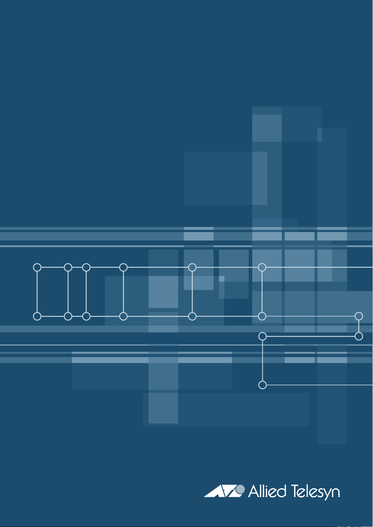
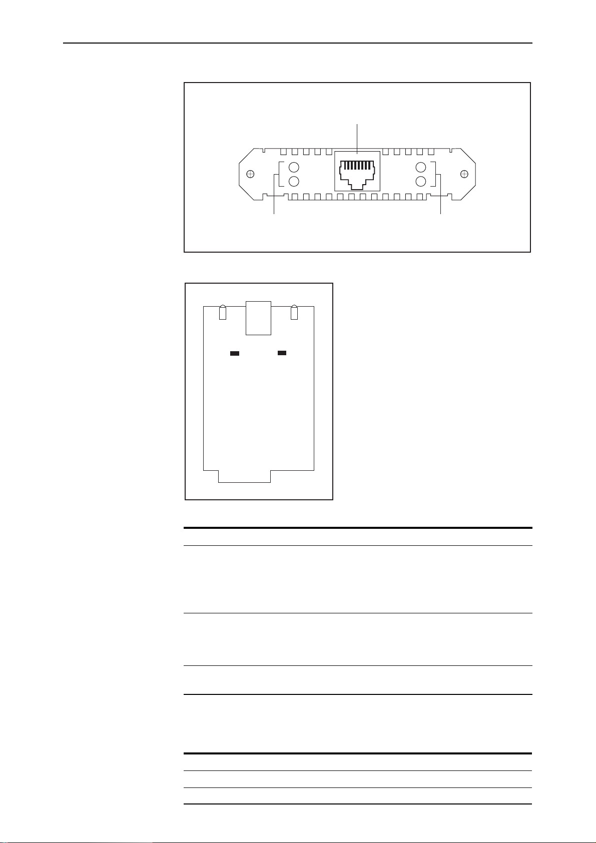
AT-AR021(S) BRI-S/T PIC ............................................................................. 7
AT-AR021(U) BRI-U PIC ............................................................................... 9
AT-AR022 ETH PIC .................................................................................... 10
AT-AR023 SYN PIC ................................................................................... 11
AT-AR024 ASYN4 PIC ............................................................................... 12
AT-AR026 4ETH PIC .................................................................................. 12
AT-AR027 VoIP-FXS PIC ............................................................................ 16
PIC Interfaces .................................................................................................. 18
Asynchronous Interface ............................................................................ 18
Synchronous Interface .............................................................................. 18
Ethernet Interfaces ................................................................................... 19
Basic Rate ISDN Interfaces ........................................................................ 19
Primary Rate ISDN Interface ...................................................................... 20
VoIP FXS Interface .................................................................................... 21
Hot Swapping ................................................................................................. 21
Hot Swapping the AR040 NSM with PICs ................................................. 22
How to Hot Swap a PIC ............................................................................ 22
Behaviour of Hot Swapped Interfaces ....................................................... 24
PIC Testing and Verification ............................................................................. 26
Cables and Loopback Plugs for PICs ................................................................ 29
Transition Cables for the AT-AR023 PIC ..................................................... 29
ISDN Interface Cables ............................................................................... 37
BT Adaptor Cable for the AT-AR027 PIC ................................................... 38
Terminal and Modem Cables .................................................................... 38
Ethernet Transceivers and AUI Cables ....................................................... 40
Loopback Plugs for Testing Interfaces ....................................................... 41
Test Facility ..................................................................................................... 44
Asynchronous Interface Tests .................................................................... 45
WAN Port Tests ......................................................................................... 45
Troubleshooting .............................................................................................. 45
For More Information ...................................................................................... 46

4Port Interface Card
C613-03023-00 REV J
Models Covered by this Reference
This Hardware Reference includes information on the following models:
■AT-AR020 PRI E1/T1
■AT-AR021 (S) BRI- S/T
■AT-AR021 (U) BRI-U
■AT-AR022 ETH
■AT-AR023 SYN
■AT-AR024 ASYN4
■AT-AR026 4ETH
■AT-AR027 VoIP-FXS
The latest Hardware Reference can be found at
www.alliedtelesyn.co.nz/support/support.html.
Why You Should Read this Reference
This Reference has been developed to familiarise you with the hardware
features of Port Interface Cards (PICs). The Reference provides information
that will assist you with the process of using and maintaining PICs.

Hardware Reference 5
C613-03023-00 REV J
PIC Overview
PICs provide a cost effective and flexible mechanism for adding new or
additional network interfaces to switches or routers. By adding or changing
PICs, network interface capabilities can be upgraded without replacing the
switch or router. A PIC can provide additional network interfaces, or can be
replaced with a different PIC to provide alternative interface types.
The following PICs are currently available:
■“AT-AR020 PRI E1/T1 PIC” with primary rate ISDN
■“AT-AR021(S) BRI-S/T PIC” with basic rate ISDN
■“AT-AR021(U) BRI-U PIC” with basic rate ISDN
■“AT-AR022 ETH PIC” with a dual Ethernet 10BASE-T/AUI port
■“AT-AR023 SYN PIC” with a single 2Mbps synchronous port
■“AT-AR024 ASYN4 PIC” with four asynchronous ports
■“AT-AR026 4ETH PIC” with four 10BASE-T/100BASE-TX ports
■“AT-AR027 VoIP-FXS PIC” with two Foreign Exchange Voice over IP ports
See the following hardware descriptions for more information on each PIC.
Hardware Features Common to All Models
This section outlines the hardware features that are common to all PIC models.
Environmental Conditions
• Operating temperature range: 0 to 40º C (32 to 104º F)
• Storage temperature range: -25 to 70º C (-13 to 158º F)
• Relative humidity range: 5 to 95% non-condensing
Regulatory Standards
• EMC: CISPR22 class A, FCC class A, and VCCI class I
• Immunity testing to EN50082 levels 2 (ESD), 3 (susceptibility), 4 (fast
transients), 5 (power surge), and 6 (RF immunity)
• Safety: UL1950, CSA22.2, EN60950 and CE

6Port Interface Card
C613-03023-00 REV J
PIC Model Descriptions
This section provides detailed information on the features of each PIC model.
AT-AR020 PRI E1/T1 PIC
The AT-AR020 PRI E1/T1 PIC provides a single G.703/Primary Rate ISDN
WAN port with an RJ-45 connector.
The card supports both E1 and T1 operation. A jumper selects the required
option and impedance. A second jumper selects NT (Network Terminator) or TE
(Terminal Equipment) mode, and the current mode is displayed by the NT LED.
The normal operating mode is LT. Jumper locations are shown in Figure 2 on
page 7, and jumper functions are listed in Table 2 on page 7.
The AT-AR020 PRI E1/T1 PIC is shown in Figure 1, and the functions of the
LEDs are listed in Table 1.
Figure 1: AT-AR020 PRI E1/T1 PIC
Table 1: AT-AR020 PRI E1/T1 PIC LED functions
LED Function
D Data [ISDN mode only] Lit when HDLC packets are being exchanged between
the switch or router and the ISDN switch over the D (signalling) channel.
B Data Lit when HDLC packets are being exchanged between the switch or
routerandanotherend system device (normallyanotherswitchorrouter)
over any of the B (data) channels.
Active Lit whenever operational (i.e., no RAI or AIS) frames are being received.
NT [ISDN mode only] Lit when the PRI1 is operating in NT mode. This LED
should not be lit during normal operation.
Active
LEDs
PRI E1/T1 (RJ45 connector)
D Data
B Data
LEDs
PIE1T1R
PRI E1/T1
NT

Hardware Reference 7
C613-03023-00 REV J
Figure 2: Location of jumpers on the AT-AR020 PRI E1/T1 PIC board
Jumper J1 is factory set to ISDN TE mode for normal operation and should not
be changed without contacting your ISDN service provider, or authorised
Allied Telesyn distributor or reseller.
Earlier versions of this card also have a J3 interface jumper. If present, this
jumper must be installed for E1 mode and removed for T1 mode.
Remove the data cable from the RJ-45 connector before attempting to remove
the PIC from the switch or router.
AT-AR021(S) BRI-S/T PIC
The AT-AR021(S) BRI-S/T PIC provides a single Basic Rate ISDN S/T WAN
port. The BRI port has an RJ-45 connector.
The AT-AR021(S) PIC is shown in Figure 3 and the functions of the LEDs are
listed in Table 3 on page 8. Jumper locations are shown in Figure 4 on page 8,
and jumper functions are listed in Table 3 on page 8.
Table 2: Functions of jumpers on the AT-AR020 PRI E1/T1 PIC board
Jumper Function Default
J1 Selects ISDN NT mode (installed) or TE mode (not installed). Not installed.
J2 Selects T1 mode (installed) or E1 mode (not installed). Not installed.
PIE1T1C
S/N
PIC CONNECTOR
LED
D Data
B Data
LED
Active
NT
RJ45
J2 (E1/T1)
J1 (NT/TE)
PRI

8Port Interface Card
C613-03023-00 REV J
Figure 3: AT-AR021(S) BRI-S/T PIC
Figure 4: Location of jumpers on the AT-AR021(S) BRI-S/T PIC board
Table 3: AT-AR021(S) BRI-S/T PIC LED functions
LED Function
B1, B2 For on-demand ISDN, lit when there is a call up over the respective B
channel and flashing when data is being exchanged.
For permanent circuits, lit when HDLC packets are being exchanged
betweentheswitchorrouterand anotherTEend systemdevice(normally
another switch or router) over the respective B (data) channel.
Active Lit when the BRI has successfully completed the exchange of INFO 1 and
INFO2 signals,andINFO 3and INFO4 signals arepresenton thelink.This
means that the ISDN interface is correctly connected to a working NT
device.
D Lit when HDLC packets are being exchanged between the switch or
router and the ISDN switch over the D (signalling) channel.
Table 4: Functions of jumpers on the AT-AR021(S) BRI-S/T PIC board
Jumper Function
J1 100Ωtermination for TX.
J2 100Ωtermination for RX.
BRI S/T
Active
D
LEDs
ISDN BRI S/T port (RJ45 connector)
B1
B2
LEDs
PIBRI1R
PIC CONNECTOR
ISDN TX
TERMINATION ISDN RX
TERMINATION
J1 J2
RJ45
BRI
LED
LED
Active
DB1
B2
PIBRI1C

Hardware Reference 9
C613-03023-00 REV J
The termination jumpers (J1 and J2) are normally removed as the building
wiring will provide the correct termination for an ISDN TE-to-NT circuit.
When the BRI is connected in a point-to-point configuration, J1 and J2 may
need to be installed to terminate the line pairs with internal 100Ωresistors. For
detailed information, see the Integrated Services Digital Network (ISDN) chapter
of the Software Reference or Reference Manual for your switch or router.
If you are unsure of whether to terminate the line or not, contact your ISDN
service provider, or your authorised Allied Telesyn distributor or reseller.
AT-AR021(U) BRI-U PIC
The AT-AR021(U) BRI-U PIC provides a single Basic Rate ISDN U Interface
WAN port. The BRI port has an RJ-45 connector.
There are no user-configurable jumpers or dip switches on the AT-AR021(U)
BRI-U PIC board.
The AT-AR021(U) PIC is shown in Figure 5, and the functions of the LEDs are
listed in Table 5.
Figure 5: AT-AR021(U) BRI-U PIC
BeforeremovingthisPIC, ensurethat thepower tothe switchorrouterhas been
disconnected and that the ISDN connection has been removed from the BRI U
interface connector. Dangerous voltages may be present on an ISDN line
interface.
Table 5: AT-AR021(U) BRI-U PIC LED functions
LED Function
B1, B2 Lit when HDLC packets are being exchanged between the switch or
router and another TE end system device (normally another switch or
router) over the respective B (data) channel
For ISDN, lit when there is a call up over the respective B channel and
flashing when data is being exchanged.
Active Lit when the U interfaceis in the Activatedstate(i.e., it is fully operational
at layer 1).
D Lit when HDLC packets are being exchanged between the switch or
router and the ISDN switch over the D (signalling) channel.
PIBRI1UR
Active
LEDs
ISDN BRI U interface (RJ45 connector)
BRI U
D
B1
B2

10 Port Interface Card
C613-03023-00 REV J
AT-AR022 ETH PIC
The AT-AR022 ETH PIC provides a dual Ethernet 10BASE-T/AUI port. Only
one interface type can be active at any one time and the PIC automatically
senses which interface is in use. The 10BASE-T interface uses an RJ-45
connector and the AUI interface uses a DB15 connector.
AT-AR022 ETH PICs are not recommended for use in AT-AR040 NSM PIC
bays because performance of these interfaces is likely to be reduced and packet
loss may occur.
The AT-AR022 ETH PIC is shown in Figure 6, and the functions of the LEDs are
listed in Table 6.
Figure 6: AT-AR022 ETH PIC
The AT-AR022 PIC is a single card. Figure 7 shows the layout of the board.
Table 6: AT-AR022 ETH PIC LED functions
LED Function
Link Lit when the Ethernet interface is connected to a device (e.g. a hub) which is
generating link pulses.
Data Lit when data is being transmitted or received over the Ethernet interface.
PIETH1R
Ethernet 10BASET port
(RJ45 connector)
Ethernet AUI port
(DB15 connector)
LEDs
Data
ETH
Link

Hardware Reference 11
C613-03023-00 REV J
Figure 7: Location of main components on the AT-AR022 ETH PIC.
AT-AR023 SYN PIC
The AT-AR023 SYN PIC provides a single synchronous port operating at
speeds up to 2Mbps. The synchronous port has a 50-way AMPLIMITE
universal connector which supports RS-232/V.28, V.35 and X.21 interface
standards in DTE and DCE modes.
A transition cable is required to convert the AMPLIMITE connector to the
correct physical interface. The switch does not need to be rebooted to change
the interface type.
There are no user-configurable jumpers or dip switches on the AT-AR023 SYN
PIC board.
The AT-AR023 SYN PIC is shown in Figure 8, and the functions of the LEDs are
listed in Table 7.
Figure 8: AT-AR023 SYN PIC
ETHERNET
10BASET
PIC CONNECTOR
PIETH1C
RJ45
LED
LED
Data Link
SYN
Synchronous port (AMPLIMITE 50-way connector)
Tx
Rx
LEDs
PISYN1R

12 Port Interface Card
C613-03023-00 REV J
AT-AR024 ASYN4 PIC
The AT-AR024 ASYN4 PIC provides four additional asynchronous RS-232
ports with RJ-45 connectors for use up to 115 Kbps.
There are no user-configurable jumpers or dip switches on the AT-AR024
ASYN4 PIC board.
The AT-AR024 ASYN4 PIC is shown in Figure 9. The ASYN4 PIC does not
have LEDs.
Figure 9: AT-AR024 ASYN4 PIC
AT-AR026 4ETH PIC
The AT-AR026 4ETH PIC provides four 10BASE-T/100 BASE-TX auto-
negotiating ports. The ports support wire speed unmanaged layer 2 switching
and have RJ-45 connectors.
The AT-AR026 4ETH PIC is shown in Figure 10, and the functions of the LEDs
are listed in Table 8 on page 13.
AT-AR026 4ETH PICs are not recommended for use in AT-AR040 NSM PIC
bays because performance of these interfaces is likely to be reduced and packet
loss may occur.
Table 7: AT-AR023 SYN PIC LED functions
LED Function
Tx Lit when data is being transmitted over the synchronous interface.
Rx Lit when data is being received on the synchronous interface.
ASYN
Asynchronous ports (RJ45 connector)
PIASYN4R
30

Hardware Reference 13
C613-03023-00 REV J
Figure 10: AT-AR026 4ETH PIC
AT-AR026 features include:
• Five integrated switch ports with physical layer transceivers (four 10/
100 Ethernet switch ports, and one fixed 10 Mbps port acting as the PIC
to base unit connector)
• 128 kbytes of frame buffering SRAM
• 1.4 Gbps high performance memory bandwidth
• 10BASE-T and 100BASE-TX modes of operation
• LED indicators for link, activity, full/half duplex, and port speed
• Hardware based 10/100, full/half duplex, flow control, and auto-
negotiation
• Individual port forced modes (full duplex, 100BASE-TX) when auto-
negotiation is disabled
• Wire speed reception and transmission
• Integrated address look-up engine, supporting 1K absolute MAC
addresses
• Automatic address learning, address aging, and address migration
• Broadcast storm protection
• Full duplex IEEE 802.3x flow control
• Half duplex back pressure flow control
• MDI/MDI-X auto cross over support
Some features (such as autonegotiation, buffer size, and MAC address aging)
are configured by adding or removing links on the PIC’s PCB. Table 9 on
page 15 lists the configurable features, their respective links, and their default
settings.
Table 8: AT-AR026 4ETH PIC LED functions (Two LEDs per port)
LED Function
Left Lit when the port is operating at 100Mbps and full duplex.
Right Lit when a link has been established. Flashing when data is being transmitted
through the port.
10BaseT/100BaseTX Ethernet ports
(RJ45 connectors)
AR026PIC
41
LEDs
10/100 ETH

14 Port Interface Card
C613-03023-00 REV J
The AT-AR026 PIC is a single card. Figure 11 shows the layout of its board and
configurable links. AT-AR026 PICs do not support the AlliedWare Diagnostic
or Test Facility modules.
AT-AR026 PICs include a switch chip that switches independently of the
switch, router, or NSM that the PIC is installed in. The show interface
command will show each correctly installed AT-AR026 as a single interface (the
PIC connector). The 10/100 ‘front side’ Ethernet ports will not be shown.
Figure 11: Location of user configurable links on the AR026 4ETH PIC
Up = 10kΩ link between pads 1 and 2
Down = 1kΩ link between pads 2 and 3
Floating = No links
All configurable links use 603 resistors
1 2 3
Pads
Ethernet ports
PIC connector
Link Detail
AR026Card
Configurable links
Link Options
Links 22, 31, 40, and MRXD 3 are fixed and
cannot be configured
Link

Hardware Reference 15
C613-03023-00 REV J
Table 9: Configurable links on the AT-AR026 4ETH PIC
Function Link Up1Down2Floating3Default
Set flow control on all Ethernet ports 13 Flow control No flow control NA Up
Force 10BASE-T4, 100BASE-TX4, or
auto-negotiation on port 1 41 100BASE-TX 10BASE-T Auto-negotiation Floating
Force 10BASE-T5, 100BASE-TX5, or
auto-negotiation on port 2 42 100BASE-TX 10BASE-T Auto-negotiation Floating
Force 10BASE-T6, 100BASE-TX6, or
auto-negotiation on port 3 43 100BASE-TX 10BASE-T Auto-negotiation Floating
Force 10BASE-T7, 100BASE-TX7, or
auto-negotiation on port 4 30 100BASE-TX 10BASE-T Auto-negotiation Floating
Force full duplex4, half duplex4, or
auto-negotiation on port 1 50 Full duplex Half duplex Auto-negotiation Floating
Force full duplex5, half duplex5, or
auto-negotiation on port 2 51 Full duplex Half duplex Auto-negotiation Floating
Force full6, half duplex6, or auto-
negotiation on port 3 52 Full duplex Half duplex Auto-negotiation Floating
Force full duplex7, half duplex7, or
auto-negotiation on port 4 53 Full duplex Half duplex Auto-negotiation Floating
Set aggressive back-off mode in half
duplex 20 Aggressive back-
off Standard back-off NA Up
Set back pressure in half duplex 21 Back pressure
enabled No back pressure NA Up
Set aging in MAC address look-up
table 23 Addressesageout
after 5 minutes No address age out NA Up
Set a maximum limit for broadcast
frames 32 Broadcast frames
are limited to a
maximumof25%
of frames
No limit on
broadcast frames NA Up
Drop packets if excessive collisions
occur 33 Packet
transmission will
continue
regardless of
collisions
Packets will be
dropped after 16
collisions
NA Down
Enable or disable auto-negotiation
on port 1 MCOL Disable auto-
negotiation Enable auto-
negotiation NA Down
Enable or disable auto-negotiation
on port 2 MRXD 0 Disable auto-
negotiation Enable auto-
negotiation NA Down
Enable or disable auto-negotiation
on port 3 MRXD 1 Disable auto-
negotiation Enable auto-
negotiation NA Down
Enable or disable auto-negotiation
on port 4 MRXD 2 Disable auto-
negotiation Enable auto-
negotiation NA Down
Set 205 buffers (maximum) per port 10 & 11 NA 1k (link 10), 1k (link
11) NA NA
Set 512 buffers (maximum) per port 10 & 11 10k (link 11) 1k (link 10) NA NA
Set 768 buffers (maximum) per port 10 & 11 10k (link 10) 1k (link11) NA NA
Set 512 buffers (adaptive) per port 10 & 11 10k (link 10),
10k (link 11) NA NA Up (link 10)
Up (link 11)

16 Port Interface Card
C613-03023-00 REV J
Notes for Table 9 on page 15.
1. Up = 10kΩlink between pads 1 and 2.
2. Down = 1kΩlink between pads 2 and 3
3. Floating = no link
4. Requires auto-negotiation on port 1 to be disabled (using link MCOL).
5. Requires auto-negotiation on port 2 to be disabled (using link MRXD 0).
6. Requires auto-negotiation on port 3 to be disabled (using link MRXD 1).
7. Requires auto-negotiation on port 4 to be disabled (using link MRXD 2).
Links 22, 31, 40, and MRXD 3 are fixed and should not be changed. Attempting
to change these links will cause the PIC to cease functioning.
AT-AR027 VoIP-FXS PIC
The AT-AR027 VoIP-FXS PIC provides two Foreign Exchange Subscriber (FXS)
ports. The ports use RJ-11 connectors and can be connected to standard analog
telephony equipment such as telephones, fax machines and modems. The FXS
interface supplies ring, voltage and dial tone.
The AT-AR027 VoIP-FXS PIC is shown in Figure 12, and functions of the LEDs
are listed in Table 10 on page 17.
Figure 12: AT-AR027 VoIP-FXS PIC
AT-AR027 features include:
• Settable ring wave form
• Settable tone generation
• Settable port gain/attenuation for transmit and receive on each port
• 600r, 600c, 900c, Cplx and Cplx2 port impedance.
• Frame buffer management
• Voice activation and silence detection
• Compatible with H.233, Session Initiation Protocol (SIP) and Media
Gateway Control Protocol (MGCP)
When using AT-AR027 PICs with an AR740 router and NSM, a maximum of
four AT-AR027 PICs can be installed in the router and NSM.
More information on protocols and how to configure them on the PIC can be
found in the Software Reference for your switch or router.
AR027PIC
10
FXS
OFF HOOK
/RING
PIC REG
OFF HOOK
/RING
PIC ERROR
Two FXS VoIP Ports
(RJ-11 connectors)
Four LEDs

Hardware Reference 17
C613-03023-00 REV J
Table 10: AT-AR027 VoIP-FXS PIC LED functions
LED State Function
Off Hook/Ring Off The port is on-hook
Green The port is off-hook
Flashing An incoming call is present on the port
PIC Reg Off The PICis not registered witha gatekeeper and
external phone calls cannot be made
Flashing The PIC is registered with a gatekeeper or
gatekeeper has been set to “None”. External
calls can only be made if the PIC is registered
with a gatekeeper
PIC Error Off The PIC is okay
Green An internal error has occurred. Reset the PIC
using the reset voip command

18 Port Interface Card
C613-03023-00 REV J
PIC Interfaces
This section provides detailed information on the physical and operational
characteristics of PIC interfaces.
Asynchronous Interface
The AT-AR024 ASYN4 PIC provides an asynchronous interface with four
ports. The interface follows the RS-232 standard and uses RJ-45 connectors.
Table 11 lists the port pin assignments.
A range of speeds is selectable using the set port command if using a router, or
the set asyn command if using a switch. More information on these commands
can be found in the Interfaces chapter of the Software Reference for your switch
or router.
Not all signals need to be connected. In particular, both DCD and CTS are not
required unless the interface has been specifically set up to use them. The
Terminal Server and Printer Server chapters of the Software Reference or
Reference Manual for your switch or router have more details. A typical
terminal connection will only require RXD, TXD and GND, but refer to the
equipment manual for the connected device for more specific data.
If LPD-based printer ports are required, then the switch or router may expect to
‘see’ the DTR signal from the printer connected to the DCD pin of the switch.
This is used to detect both the fact that the printer is ‘online’ and that it is
‘powered-on’. This prevents print jobs being sent to a disconnected printer and
lost. The Printer Server chapter of the Software Reference or Reference Manual
for your switch or router has more information.
Synchronous Interface
The AT-AR023 SYN PIC provides a synchronous interface with a single
AMPLIMITE 50-way port. The AMPLIMITE port is wired as a universal
connector for RS-232/V.28, V.35 and X.21 interface standards in both DTE and
DCE modes. A transition cable is required to convert the AMPLIMITE to the
correct physical interface for the standard required (e.g., DB15 for X.21). The
transition cable can be ordered from your supplier, or you can construct your
own cable.
Table 11: Pinout of the RJ-45 connectors on the AT-AR024 ASYN4 PIC
Pin* Function Signal Direction
1 RING Input to PIC
2 DCD Input to PIC
3 DTR Output from PIC
4GND
5 RXD Input to PIC
6 TXD Output from PIC
7 CTS Input to PIC
8 RTS Output from PIC
*Pins are numbered from left to right.

Hardware Reference 19
C613-03023-00 REV J
The transition cable does more than simply change the physical connector. The
switch or router hardware reads the cable type from the AMPLIMITE plug and
enables or disables the internal driver electronics as required. To function
correctly, the cables must be identical to the cables described in “Cables and
Loopback Plugs for PICs” on page 29.
The DCE cable type reverses the direction of the data lines as well as the clock
lines. This cable is intended to be used when the switch or router supplies the
clock for the attached device. This is commonly used when the switch or router
is connected to the synchronous interface of another device or a host, without
using an intermediate modem or NTU (Network Terminating Unit). Therefore,
the DCE cable must only be connected to a switch or router interface that is set
to generate the clock. The Interfaces chapter of the Software Reference or
Reference Manual for your switch or router has more information.
The transition cable can be changed at any time. It is not necessary to power-
down the switch.
When an RS-232 DCE transition cable is connected to a synchronous interface
configured to generate clocks, the maximum clock speed is 38400 bps. When an
X.21 DCE or V.35 DCE transition cable is connected to a synchronous interface
configured to generate clocks, the maximum clock speed is 2 Mbps.
Ethernet Interfaces
Dual 10BASE-T/AUI Interfaces
The AT-AR022 ETH PIC has a dual 10BASE-T/AUI Ethernet interface. Only
one Ethernet interface type can be active at any one time. The PIC auto-senses
which Ethernet interface type is in use.
For performance reasons, the AT-AR022 PIC is not recommended for use in the
AT-AR040 NSM. When the AT-AR040 NSM is installed in a switch or switching
router, Ethernet connections should be made through the Ethernet ports. When
the AT-AR040 NSM is installed in a router, AT-AR022 PICs should be installed
in base-unit (router) PIC bays.
10Base-T/100Base-TX Interfaces
The AT-AR026 4ETH PIC has four 10BASE-T/100BASE-TX ports with RJ-45
connectors. Port characteristics such as speed, flow control, half/full duplex,
and auto-negotiation can be set by configuring links on the PIC’s PCB. See
“AT-AR026 4ETH PIC” on page 12 for more information.
Basic Rate ISDN Interfaces
The AT-AR021(S) BRI-S/T and AT-AR021(U) PICs provide Basic Rate ISDN
(BRI) interfaces. In both cases the connecter type is RJ-45. The interfaces
support two 64K B channels and one D channel.
For the AT-AR021(S) BRI-S/T PIC, the operational mode of the BRI ISDN
interface (TE or NT) is determined by jumpers mounted on its board. See
“AT-AR021(S) BRI-S/T PIC” on page 7 for locations and names of the jumpers.
The AT-AR021(U) PIC only supports TE mode. The Integrated Services Digital
Network (ISDN) chapter of the Software Reference or Reference Manual for

20 Port Interface Card
C613-03023-00 REV J
your switch or router has detailed descriptions of the two operational modes.
The switch or router should be configured as a TE for normal operation.
For the AT-AR021(S) BRI-S/T PIC, the termination provided by the interface
may also be determined by jumpers mounted on its board. The jumpers are
normally removed as the building wiring will provide the correct termination
for an ISDN TE-to-NT circuit.
When the BRI is connected in a point-to-point configuration, the jumpers may
need to be installed to terminate the line pairs with internal 100Ωresistors. See
“AT-AR021(S) BRI-S/T PIC” on page 7 for locations and names of the jumpers.
The Integrated Services Digital Network (ISDN) chapter of the Software Reference
or Reference Manual for your switch or router has additional information. The
pinout of the BRI interface is shown in Table 12.
If you are unsure of whether to terminate the line or not, contact your ISDN
service provider or your Authorised Allied Telesyn distributor or reseller.
Primary Rate ISDN Interface
The AT-AR020 PRI E1/T1 PIC provides a Primary Rate ISDN interface with a
single RJ-45 connector. The interface supports connection to either 100ΩT1 or
120ΩE1 networks.
Table 2 on page 7 lists the network jumper settings for the different network
types.
Table 12: Pinout of the Basic Rate ISDN interface
Pin S/T Interface Functions U Interface Functions
1- -
2- -
3TX+ -
4RX+ positive(+)
5RX- negative(-)
6TX- -
7- -
8- -
Table 13: Connection standard for Primary Rate ISDN RJ-45 connectors
Pin* Signal
1RX+
2RX-
3 RX ground selection from jumper
4TX+
5TX-
6 TX ground selection from jumper
7Not connected
8Not connected
*Pins are numbered from left to right, with latch down, as viewed from the rear.
Other manuals for AT-AR020 PRI E1/T1
6
This manual suits for next models
14
Table of contents
Other Allied Telesis Recording Equipment manuals