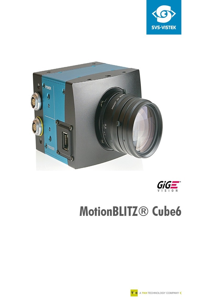
Allied Vision MAKO U-029B User manual

USB3 VISION CAMERAS
Mako U
Technical Manual
V1.1.3
Allied Vision Technologies GmbH // Taschenweg 2a, 07646 Stadtroda / Germany 2018-Jan-16

Mako U at a glance
2Mako U Technical Manual V1.1.3
Mako U at a glance
Delivery contents
Your Mako U delivery consists of the following items:
• Shipping box
•MakoUcamera
•USB3 Vision Cameras Quickstart Guide.
What else do you need?
The following downloads provide additional information and software.
Read this manual carefully
Learn how to protect your camera from damage and fully understand its
functions.
Micro-B USB 3.0 cable not included
You need a Micro-B USB 3.0 cable to connect your Mako U camera to a host adapter.
• For USB 3.0 accessories, see USB 3.0 cards, hubs, and cables on page 58.
• For ordering USB 3.0 accessories, see
https://www.alliedvision.com/en/meta-header/contact/contact-sales.
Notice
Avoid damage to the camera by exceeding the allowed temperature range
Operating the camera beyond the allowed maximum temperature can damage the
camera.
• For operation, keep the housing temperature between +5 °C and +45 °C
(see Specifications on page 24).
• Follow the instructions described in Heat dissipation on page 23.
Document Web link
USB3 Vision Cameras Quickstart Guide
USB Features Reference
https://www.alliedvision.com/en/support/technical-
documentation, at Additional Documents for the Mako U
camera.
USB Triggering Concept https://www.alliedvision.com/en/support/technical-papers-
knowledge-base
Software Web link
Vimba, including Vimba Viewer and
Vimba Driver Installer for Windows
https://www.alliedvision.com/software
Table 1: Mako U, additional downloads overview

Contact us
3Mako U Technical Manual V1.1.3
Contact us
Connect with Allied Vision by function
https://www.alliedvision.com/en/meta-header/contact
Find an Allied Vision office or distributor
https://www.alliedvision.com/en/about-us/where-we-are
Email
support@alliedvision.com
Telephone
EMEA: +49 36428-677-0
The Americas: +1 978-225-2030
Asia-Pacific: +65 6634-9027
China: +86 (21) 64861133
Headquarters
Allied Vision Technologies GmbH
Taschenweg 2a
07646 Stadtroda
Germany
Tel: +49 (0)36428 677-0
Fax: +49 (0)36428 677-28
President/CEO: Frank Grube
Registration Office: AG Jena HRB 208962

Contents
4Mako U Technical Manual V1.1.3
Contents
Mako U at a glance. . . . . . . . . . . . . . . . . . . . . . . . . . . . . . . . . . . . . . . . . . . . . . . . . . . . . . . . . . . . . . . . . . 2
Delivery contents. . . . . . . . . . . . . . . . . . . . . . . . . . . . . . . . . . . . . . . . . . . . . . . . . . . . . . . . . . . . . . . . . . . . . . . . . . . 2
What else do you need? . . . . . . . . . . . . . . . . . . . . . . . . . . . . . . . . . . . . . . . . . . . . . . . . . . . . . . . . . . . . . . . . . . . . . 2
Contact us . . . . . . . . . . . . . . . . . . . . . . . . . . . . . . . . . . . . . . . . . . . . . . . . . . . . . . . . . . . . . . . . . . . . . . . . . . . . 3
Document history and conventions . . . . . . . . . . . . . . . . . . . . . . . . . . . . . . . . . . . . . . . . . . . . . . 8
Document history . . . . . . . . . . . . . . . . . . . . . . . . . . . . . . . . . . . . . . . . . . . . . . . . . . . . . . . . . . . . . . . . . . . . . . . . . . 9
Conventions used in this manual . . . . . . . . . . . . . . . . . . . . . . . . . . . . . . . . . . . . . . . . . . . . . . . . . . . . . . . . . . . . . 10
Styles . . . . . . . . . . . . . . . . . . . . . . . . . . . . . . . . . . . . . . . . . . . . . . . . . . . . . . . . . . . . . . . . . . . . . . . . . . . . . . . . 10
Symbols and notes . . . . . . . . . . . . . . . . . . . . . . . . . . . . . . . . . . . . . . . . . . . . . . . . . . . . . . . . . . . . . . . . . . . . . 10
Product naming. . . . . . . . . . . . . . . . . . . . . . . . . . . . . . . . . . . . . . . . . . . . . . . . . . . . . . . . . . . . . . . . . . . . . . . . 11
Compliance, safety, and intended use . . . . . . . . . . . . . . . . . . . . . . . . . . . . . . . . . . . . . . . . . . 12
Compliance notifications . . . . . . . . . . . . . . . . . . . . . . . . . . . . . . . . . . . . . . . . . . . . . . . . . . . . . . . . . . . . . . . . . . . 13
For customers in Europe:. . . . . . . . . . . . . . . . . . . . . . . . . . . . . . . . . . . . . . . . . . . . . . . . . . . . . . . . . . . . . . . . 13
For customers in the USA. . . . . . . . . . . . . . . . . . . . . . . . . . . . . . . . . . . . . . . . . . . . . . . . . . . . . . . . . . . . . . . . 13
Avoid electromagnetic interferences . . . . . . . . . . . . . . . . . . . . . . . . . . . . . . . . . . . . . . . . . . . . . . . . . . . . . . 13
Camera applications and intended use . . . . . . . . . . . . . . . . . . . . . . . . . . . . . . . . . . . . . . . . . . . . . . . . . . . . . . . . 14
General use . . . . . . . . . . . . . . . . . . . . . . . . . . . . . . . . . . . . . . . . . . . . . . . . . . . . . . . . . . . . . . . . . . . . . . . . . . . 14
Use in medical devices . . . . . . . . . . . . . . . . . . . . . . . . . . . . . . . . . . . . . . . . . . . . . . . . . . . . . . . . . . . . . . . . . . 14
Copyright and trademarks . . . . . . . . . . . . . . . . . . . . . . . . . . . . . . . . . . . . . . . . . . . . . . . . . . . . . . . . . . . . . . . 14
Safety . . . . . . . . . . . . . . . . . . . . . . . . . . . . . . . . . . . . . . . . . . . . . . . . . . . . . . . . . . . . . . . . . . . . . . . . . . . . . . . . . . . 15
Electrical connections. . . . . . . . . . . . . . . . . . . . . . . . . . . . . . . . . . . . . . . . . . . . . . . . . . . . . . . . . . . . . . . . . . . 15
Optical components . . . . . . . . . . . . . . . . . . . . . . . . . . . . . . . . . . . . . . . . . . . . . . . . . . . . . . . . . . . . . . . . . . . . 21
Heat dissipation . . . . . . . . . . . . . . . . . . . . . . . . . . . . . . . . . . . . . . . . . . . . . . . . . . . . . . . . . . . . . . . . . . . . . . . 23
BIOS drivers . . . . . . . . . . . . . . . . . . . . . . . . . . . . . . . . . . . . . . . . . . . . . . . . . . . . . . . . . . . . . . . . . . . . . . . . . . . 23
Specifications . . . . . . . . . . . . . . . . . . . . . . . . . . . . . . . . . . . . . . . . . . . . . . . . . . . . . . . . . . . . . . . . . . . . . . . 24
Applied standards . . . . . . . . . . . . . . . . . . . . . . . . . . . . . . . . . . . . . . . . . . . . . . . . . . . . . . . . . . . . . . . . . . . . . . . . . 25
GenICam . . . . . . . . . . . . . . . . . . . . . . . . . . . . . . . . . . . . . . . . . . . . . . . . . . . . . . . . . . . . . . . . . . . . . . . . . . . . . 25
USB 3.0. . . . . . . . . . . . . . . . . . . . . . . . . . . . . . . . . . . . . . . . . . . . . . . . . . . . . . . . . . . . . . . . . . . . . . . . . . . . . . . 25
USB3 Vision . . . . . . . . . . . . . . . . . . . . . . . . . . . . . . . . . . . . . . . . . . . . . . . . . . . . . . . . . . . . . . . . . . . . . . . . . . . 25
IP class . . . . . . . . . . . . . . . . . . . . . . . . . . . . . . . . . . . . . . . . . . . . . . . . . . . . . . . . . . . . . . . . . . . . . . . . . . . . . . . 25
Notes on specifications. . . . . . . . . . . . . . . . . . . . . . . . . . . . . . . . . . . . . . . . . . . . . . . . . . . . . . . . . . . . . . . . . . . . . 26
Power consumption . . . . . . . . . . . . . . . . . . . . . . . . . . . . . . . . . . . . . . . . . . . . . . . . . . . . . . . . . . . . . . . . . . . . 26
Frame memory . . . . . . . . . . . . . . . . . . . . . . . . . . . . . . . . . . . . . . . . . . . . . . . . . . . . . . . . . . . . . . . . . . . . . . . . 26
User data memory . . . . . . . . . . . . . . . . . . . . . . . . . . . . . . . . . . . . . . . . . . . . . . . . . . . . . . . . . . . . . . . . . . . . . 26
Fixed frame rate control. . . . . . . . . . . . . . . . . . . . . . . . . . . . . . . . . . . . . . . . . . . . . . . . . . . . . . . . . . . . . . . . . 27
Trigger latency. . . . . . . . . . . . . . . . . . . . . . . . . . . . . . . . . . . . . . . . . . . . . . . . . . . . . . . . . . . . . . . . . . . . . . . . . 27
ExposureMode . . . . . . . . . . . . . . . . . . . . . . . . . . . . . . . . . . . . . . . . . . . . . . . . . . . . . . . . . . . . . . . . . . . . . . . . 27
Absolute quantum efficiency (QE) plots . . . . . . . . . . . . . . . . . . . . . . . . . . . . . . . . . . . . . . . . . . . . . . . . . . . . 27

Contents
5Mako U Technical Manual V1.1.3
ROI frame rates . . . . . . . . . . . . . . . . . . . . . . . . . . . . . . . . . . . . . . . . . . . . . . . . . . . . . . . . . . . . . . . . . . . . . . . . 28
Mako U-029B/051B/130B characteristics. . . . . . . . . . . . . . . . . . . . . . . . . . . . . . . . . . . . . . . . . . . . . . . . . . . . . . 29
Black Level Compensation for PYTHON sensor cameras. . . . . . . . . . . . . . . . . . . . . . . . . . . . . . . . . . . . . . . 29
Mako U-029B specifications. . . . . . . . . . . . . . . . . . . . . . . . . . . . . . . . . . . . . . . . . . . . . . . . . . . . . . . . . . . . . . . . . 30
Mako U-029B absolute quantum efficiency . . . . . . . . . . . . . . . . . . . . . . . . . . . . . . . . . . . . . . . . . . . . . . . . . 31
Mako U-029B ROI frame rates. . . . . . . . . . . . . . . . . . . . . . . . . . . . . . . . . . . . . . . . . . . . . . . . . . . . . . . . . . . . 31
Mako U-051B specifications. . . . . . . . . . . . . . . . . . . . . . . . . . . . . . . . . . . . . . . . . . . . . . . . . . . . . . . . . . . . . . . . . 32
Mako U-051B absolute quantum efficiency . . . . . . . . . . . . . . . . . . . . . . . . . . . . . . . . . . . . . . . . . . . . . . . . . 33
Mako U-051B ROI frame rates. . . . . . . . . . . . . . . . . . . . . . . . . . . . . . . . . . . . . . . . . . . . . . . . . . . . . . . . . . . . 34
Mako U-130B specifications. . . . . . . . . . . . . . . . . . . . . . . . . . . . . . . . . . . . . . . . . . . . . . . . . . . . . . . . . . . . . . . . . 35
Mako U-130B absolute quantum efficiency . . . . . . . . . . . . . . . . . . . . . . . . . . . . . . . . . . . . . . . . . . . . . . . . . 36
Mako U-130B ROI frame rates. . . . . . . . . . . . . . . . . . . . . . . . . . . . . . . . . . . . . . . . . . . . . . . . . . . . . . . . . . . . 37
Mako U-503B characteristics . . . . . . . . . . . . . . . . . . . . . . . . . . . . . . . . . . . . . . . . . . . . . . . . . . . . . . . . . . . . . . . . 38
ExposureMode and triggering . . . . . . . . . . . . . . . . . . . . . . . . . . . . . . . . . . . . . . . . . . . . . . . . . . . . . . . . . . . . 38
Rolling shutter. . . . . . . . . . . . . . . . . . . . . . . . . . . . . . . . . . . . . . . . . . . . . . . . . . . . . . . . . . . . . . . . . . . . . . . . . 39
Gain . . . . . . . . . . . . . . . . . . . . . . . . . . . . . . . . . . . . . . . . . . . . . . . . . . . . . . . . . . . . . . . . . . . . . . . . . . . . . . . . . 40
Reconfiguration delay. . . . . . . . . . . . . . . . . . . . . . . . . . . . . . . . . . . . . . . . . . . . . . . . . . . . . . . . . . . . . . . . . . . 40
Mako U-503B specifications. . . . . . . . . . . . . . . . . . . . . . . . . . . . . . . . . . . . . . . . . . . . . . . . . . . . . . . . . . . . . . . . . 41
Mako U-503B absolute quantum efficiency . . . . . . . . . . . . . . . . . . . . . . . . . . . . . . . . . . . . . . . . . . . . . . . . . 42
Mako U-503B ROI frame rates. . . . . . . . . . . . . . . . . . . . . . . . . . . . . . . . . . . . . . . . . . . . . . . . . . . . . . . . . . . . 43
Mechanical dimensions . . . . . . . . . . . . . . . . . . . . . . . . . . . . . . . . . . . . . . . . . . . . . . . . . . . . . . . . . . . . . . . . . . . . 44
Mako U housing . . . . . . . . . . . . . . . . . . . . . . . . . . . . . . . . . . . . . . . . . . . . . . . . . . . . . . . . . . . . . . . . . . . . . . . 44
Lens mounts . . . . . . . . . . . . . . . . . . . . . . . . . . . . . . . . . . . . . . . . . . . . . . . . . . . . . . . . . . . . . . . . . . . . . . . . . . 45
Sensor position accuracy . . . . . . . . . . . . . . . . . . . . . . . . . . . . . . . . . . . . . . . . . . . . . . . . . . . . . . . . . . . . . . . . 46
Camera features available with Vimba. . . . . . . . . . . . . . . . . . . . . . . . . . . . . . . . . . . . . . . . . . 47
About camera features . . . . . . . . . . . . . . . . . . . . . . . . . . . . . . . . . . . . . . . . . . . . . . . . . . . . . . . . . . . . . . . . . . . . . 48
Feature standards. . . . . . . . . . . . . . . . . . . . . . . . . . . . . . . . . . . . . . . . . . . . . . . . . . . . . . . . . . . . . . . . . . . . . . 48
Features that can be saved in UserSets . . . . . . . . . . . . . . . . . . . . . . . . . . . . . . . . . . . . . . . . . . . . . . . . . . . . 48
Features list order. . . . . . . . . . . . . . . . . . . . . . . . . . . . . . . . . . . . . . . . . . . . . . . . . . . . . . . . . . . . . . . . . . . . . . 49
Selectors . . . . . . . . . . . . . . . . . . . . . . . . . . . . . . . . . . . . . . . . . . . . . . . . . . . . . . . . . . . . . . . . . . . . . . . . . . . . . 49
Camera features list . . . . . . . . . . . . . . . . . . . . . . . . . . . . . . . . . . . . . . . . . . . . . . . . . . . . . . . . . . . . . . . . . . . . . . . 50
Accessories . . . . . . . . . . . . . . . . . . . . . . . . . . . . . . . . . . . . . . . . . . . . . . . . . . . . . . . . . . . . . . . . . . . . . . . . . . 57
USB 3.0 cards, hubs, and cables. . . . . . . . . . . . . . . . . . . . . . . . . . . . . . . . . . . . . . . . . . . . . . . . . . . . . . . . . . . . . . 58
Recommended USB 3.0 accessories . . . . . . . . . . . . . . . . . . . . . . . . . . . . . . . . . . . . . . . . . . . . . . . . . . . . . . . 58
6-pin Hirose I/O cables . . . . . . . . . . . . . . . . . . . . . . . . . . . . . . . . . . . . . . . . . . . . . . . . . . . . . . . . . . . . . . . . . . . . . 59
Mako tripod adapters . . . . . . . . . . . . . . . . . . . . . . . . . . . . . . . . . . . . . . . . . . . . . . . . . . . . . . . . . . . . . . . . . . . . . . 60
Mako U tripod adapter dimensions . . . . . . . . . . . . . . . . . . . . . . . . . . . . . . . . . . . . . . . . . . . . . . . . . . . . . . . 61
Filters and M12-Mount adapter . . . . . . . . . . . . . . . . . . . . . . . . . . . . . . . . . . . . . . . . . . . . . . . . . . . . . . . . . . . . . 62
Lenses: Focal length vs. field of view . . . . . . . . . . . . . . . . . . . . . . . . . . . . . . . . . . . . . . . . . . . . . . . . . . . . . . . . . 63
Installing the camera. . . . . . . . . . . . . . . . . . . . . . . . . . . . . . . . . . . . . . . . . . . . . . . . . . . . . . . . . . . . . . . 65
Prerequisites . . . . . . . . . . . . . . . . . . . . . . . . . . . . . . . . . . . . . . . . . . . . . . . . . . . . . . . . . . . . . . . . . . . . . . . . . . . . . 66
Required components . . . . . . . . . . . . . . . . . . . . . . . . . . . . . . . . . . . . . . . . . . . . . . . . . . . . . . . . . . . . . . . . . . 66
Installing the camera using Vimba on a Windows system. . . . . . . . . . . . . . . . . . . . . . . . . . . . . . . . . . . . . . . . . 67
Installing USB 3.0 host adapter and Vimba . . . . . . . . . . . . . . . . . . . . . . . . . . . . . . . . . . . . . . . . . . . . . . . . . 67

Contents
6Mako U Technical Manual V1.1.3
Installing the camera driver . . . . . . . . . . . . . . . . . . . . . . . . . . . . . . . . . . . . . . . . . . . . . . . . . . . . . . . . . . . . . . 68
Installing the camera driver with Windows tools . . . . . . . . . . . . . . . . . . . . . . . . . . . . . . . . . . . . . . . . . . . . 70
Mounting the camera . . . . . . . . . . . . . . . . . . . . . . . . . . . . . . . . . . . . . . . . . . . . . . . . . . . . . . . . . . . . . . . . . . . . . . 72
Tripod adapter . . . . . . . . . . . . . . . . . . . . . . . . . . . . . . . . . . . . . . . . . . . . . . . . . . . . . . . . . . . . . . . . . . . . . . . . 72
Camera interfaces . . . . . . . . . . . . . . . . . . . . . . . . . . . . . . . . . . . . . . . . . . . . . . . . . . . . . . . . . . . . . . . . . . 73
Back panel . . . . . . . . . . . . . . . . . . . . . . . . . . . . . . . . . . . . . . . . . . . . . . . . . . . . . . . . . . . . . . . . . . . . . . . . . . . . . . . 74
Connectors naming. . . . . . . . . . . . . . . . . . . . . . . . . . . . . . . . . . . . . . . . . . . . . . . . . . . . . . . . . . . . . . . . . . . . . 74
Back panel . . . . . . . . . . . . . . . . . . . . . . . . . . . . . . . . . . . . . . . . . . . . . . . . . . . . . . . . . . . . . . . . . . . . . . . . . . . . 74
I/O connector pin assignment . . . . . . . . . . . . . . . . . . . . . . . . . . . . . . . . . . . . . . . . . . . . . . . . . . . . . . . . . . . . . . . 75
6-pin Hirose I/O cables . . . . . . . . . . . . . . . . . . . . . . . . . . . . . . . . . . . . . . . . . . . . . . . . . . . . . . . . . . . . . . . . . . 75
Opto-isolated I/Os . . . . . . . . . . . . . . . . . . . . . . . . . . . . . . . . . . . . . . . . . . . . . . . . . . . . . . . . . . . . . . . . . . . . . . . . . 76
Input description. . . . . . . . . . . . . . . . . . . . . . . . . . . . . . . . . . . . . . . . . . . . . . . . . . . . . . . . . . . . . . . . . . . . . . . 76
Input levels . . . . . . . . . . . . . . . . . . . . . . . . . . . . . . . . . . . . . . . . . . . . . . . . . . . . . . . . . . . . . . . . . . . . . . . . . . . 76
Input timing delay and minimum pulse width . . . . . . . . . . . . . . . . . . . . . . . . . . . . . . . . . . . . . . . . . . . . . . . 76
Output description . . . . . . . . . . . . . . . . . . . . . . . . . . . . . . . . . . . . . . . . . . . . . . . . . . . . . . . . . . . . . . . . . . . . . 77
Output levels . . . . . . . . . . . . . . . . . . . . . . . . . . . . . . . . . . . . . . . . . . . . . . . . . . . . . . . . . . . . . . . . . . . . . . . . . . 78
Output switching times . . . . . . . . . . . . . . . . . . . . . . . . . . . . . . . . . . . . . . . . . . . . . . . . . . . . . . . . . . . . . . . . . 79
Non-isolated, programmable GPIOs . . . . . . . . . . . . . . . . . . . . . . . . . . . . . . . . . . . . . . . . . . . . . . . . . . . . . . . . . . 80
GPIOs description . . . . . . . . . . . . . . . . . . . . . . . . . . . . . . . . . . . . . . . . . . . . . . . . . . . . . . . . . . . . . . . . . . . . . . 80
Input levels . . . . . . . . . . . . . . . . . . . . . . . . . . . . . . . . . . . . . . . . . . . . . . . . . . . . . . . . . . . . . . . . . . . . . . . . . . . 81
Input timing delay and minimum pulse width . . . . . . . . . . . . . . . . . . . . . . . . . . . . . . . . . . . . . . . . . . . . . . . 81
Output levels . . . . . . . . . . . . . . . . . . . . . . . . . . . . . . . . . . . . . . . . . . . . . . . . . . . . . . . . . . . . . . . . . . . . . . . . . . 82
Output switching times . . . . . . . . . . . . . . . . . . . . . . . . . . . . . . . . . . . . . . . . . . . . . . . . . . . . . . . . . . . . . . . . . 82
Status LEDs. . . . . . . . . . . . . . . . . . . . . . . . . . . . . . . . . . . . . . . . . . . . . . . . . . . . . . . . . . . . . . . . . . . . . . . . . . . . . . . 84
Normal operation . . . . . . . . . . . . . . . . . . . . . . . . . . . . . . . . . . . . . . . . . . . . . . . . . . . . . . . . . . . . . . . . . . . . . . 84
Error conditions . . . . . . . . . . . . . . . . . . . . . . . . . . . . . . . . . . . . . . . . . . . . . . . . . . . . . . . . . . . . . . . . . . . . . . . 85
Triggering . . . . . . . . . . . . . . . . . . . . . . . . . . . . . . . . . . . . . . . . . . . . . . . . . . . . . . . . . . . . . . . . . . . . . . . . . . . . 86
Trigger Control features . . . . . . . . . . . . . . . . . . . . . . . . . . . . . . . . . . . . . . . . . . . . . . . . . . . . . . . . . . . . . . . . . . . . 87
TriggerSelector . . . . . . . . . . . . . . . . . . . . . . . . . . . . . . . . . . . . . . . . . . . . . . . . . . . . . . . . . . . . . . . . . . . . . . . . 87
Trigger path . . . . . . . . . . . . . . . . . . . . . . . . . . . . . . . . . . . . . . . . . . . . . . . . . . . . . . . . . . . . . . . . . . . . . . . . . . . . . . 88
Digital I/O Control . . . . . . . . . . . . . . . . . . . . . . . . . . . . . . . . . . . . . . . . . . . . . . . . . . . . . . . . . . . . . . . . . . . . . . . . . 88
TriggerMode and TriggerActivation. . . . . . . . . . . . . . . . . . . . . . . . . . . . . . . . . . . . . . . . . . . . . . . . . . . . . . . . . . . 89
TriggerMode . . . . . . . . . . . . . . . . . . . . . . . . . . . . . . . . . . . . . . . . . . . . . . . . . . . . . . . . . . . . . . . . . . . . . . . . . . 89
TriggerActivation. . . . . . . . . . . . . . . . . . . . . . . . . . . . . . . . . . . . . . . . . . . . . . . . . . . . . . . . . . . . . . . . . . . . . . . 89
TriggerDelay. . . . . . . . . . . . . . . . . . . . . . . . . . . . . . . . . . . . . . . . . . . . . . . . . . . . . . . . . . . . . . . . . . . . . . . . . . . . . . 89
Digital I/O lines. . . . . . . . . . . . . . . . . . . . . . . . . . . . . . . . . . . . . . . . . . . . . . . . . . . . . . . . . . . . . . . . . . . . . . . . . . . . 90
Input path and TriggerSource . . . . . . . . . . . . . . . . . . . . . . . . . . . . . . . . . . . . . . . . . . . . . . . . . . . . . . . . . . . . 90
Output path and LineSource . . . . . . . . . . . . . . . . . . . . . . . . . . . . . . . . . . . . . . . . . . . . . . . . . . . . . . . . . . . . . 91
Trigger signal flow . . . . . . . . . . . . . . . . . . . . . . . . . . . . . . . . . . . . . . . . . . . . . . . . . . . . . . . . . . . . . . . . . . . . . . . . . 92
Trigger latency. . . . . . . . . . . . . . . . . . . . . . . . . . . . . . . . . . . . . . . . . . . . . . . . . . . . . . . . . . . . . . . . . . . . . . . . . 92
Best practice rules for triggering . . . . . . . . . . . . . . . . . . . . . . . . . . . . . . . . . . . . . . . . . . . . . . . . . . . . . . . . . . . . . 93
Triggering when ReadoutActive is low . . . . . . . . . . . . . . . . . . . . . . . . . . . . . . . . . . . . . . . . . . . . . . . . . . . . . 93
Triggering when ReadoutActive is high. . . . . . . . . . . . . . . . . . . . . . . . . . . . . . . . . . . . . . . . . . . . . . . . . . . . . 93

Contents
7Mako U Technical Manual V1.1.3
Image data flow. . . . . . . . . . . . . . . . . . . . . . . . . . . . . . . . . . . . . . . . . . . . . . . . . . . . . . . . . . . . . . . . . . . . . 94
Mako U cameras . . . . . . . . . . . . . . . . . . . . . . . . . . . . . . . . . . . . . . . . . . . . . . . . . . . . . . . . . . . . . . . . . . . . . . . . . . 95
Image corrections for Mako U cameras . . . . . . . . . . . . . . . . . . . . . . . . . . . . . . . . . . . . . . . . . . . . . . . . . . . . 96
Firmware recovery . . . . . . . . . . . . . . . . . . . . . . . . . . . . . . . . . . . . . . . . . . . . . . . . . . . . . . . . . . . . . . . . . 97
Recovering the firmware . . . . . . . . . . . . . . . . . . . . . . . . . . . . . . . . . . . . . . . . . . . . . . . . . . . . . . . . . . . . . . . . . . . 98
Precautions . . . . . . . . . . . . . . . . . . . . . . . . . . . . . . . . . . . . . . . . . . . . . . . . . . . . . . . . . . . . . . . . . . . . . . . . . . . 98
Firmware recovery with Vimba . . . . . . . . . . . . . . . . . . . . . . . . . . . . . . . . . . . . . . . . . . . . . . . . . . . . . . . . . . . 98
LED codes for a firmware recovery . . . . . . . . . . . . . . . . . . . . . . . . . . . . . . . . . . . . . . . . . . . . . . . . . . . . . . . . . . . 99
Cleaning optical components. . . . . . . . . . . . . . . . . . . . . . . . . . . . . . . . . . . . . . . . . . . . . . . . . . . . 100
Keep optical components clean . . . . . . . . . . . . . . . . . . . . . . . . . . . . . . . . . . . . . . . . . . . . . . . . . . . . . . . . . . . . . 101
Dirt . . . . . . . . . . . . . . . . . . . . . . . . . . . . . . . . . . . . . . . . . . . . . . . . . . . . . . . . . . . . . . . . . . . . . . . . . . . . . . . . . . . . 102
Dirt vs. pixel defects . . . . . . . . . . . . . . . . . . . . . . . . . . . . . . . . . . . . . . . . . . . . . . . . . . . . . . . . . . . . . . . . . . .102
Dirt not affecting the image. . . . . . . . . . . . . . . . . . . . . . . . . . . . . . . . . . . . . . . . . . . . . . . . . . . . . . . . . . . . .102
Dirt affecting the image . . . . . . . . . . . . . . . . . . . . . . . . . . . . . . . . . . . . . . . . . . . . . . . . . . . . . . . . . . . . . . . . 102
Examining optical components for dirt . . . . . . . . . . . . . . . . . . . . . . . . . . . . . . . . . . . . . . . . . . . . . . . . . . . . . . . 103
Examination instructions . . . . . . . . . . . . . . . . . . . . . . . . . . . . . . . . . . . . . . . . . . . . . . . . . . . . . . . . . . . . . . . 103
Materials for cleaning optical components. . . . . . . . . . . . . . . . . . . . . . . . . . . . . . . . . . . . . . . . . . . . . . . . . . . .103
Cleaning instructions. . . . . . . . . . . . . . . . . . . . . . . . . . . . . . . . . . . . . . . . . . . . . . . . . . . . . . . . . . . . . . . . . . . . . .104
Troubleshooting . . . . . . . . . . . . . . . . . . . . . . . . . . . . . . . . . . . . . . . . . . . . . . . . . . . . . . . . . . . . . . . . . . .106
Questions and answers. . . . . . . . . . . . . . . . . . . . . . . . . . . . . . . . . . . . . . . . . . . . . . . . . . . . . . . . . . . . . . . . . . . .107
Camera recognition . . . . . . . . . . . . . . . . . . . . . . . . . . . . . . . . . . . . . . . . . . . . . . . . . . . . . . . . . . . . . . . . . . . 107
Unexpected events. . . . . . . . . . . . . . . . . . . . . . . . . . . . . . . . . . . . . . . . . . . . . . . . . . . . . . . . . . . . . . . . . . . . 109
Performance . . . . . . . . . . . . . . . . . . . . . . . . . . . . . . . . . . . . . . . . . . . . . . . . . . . . . . . . . . . . . . . . . . . . . . . . . 110
Radio signal interference . . . . . . . . . . . . . . . . . . . . . . . . . . . . . . . . . . . . . . . . . . . . . . . . . . . . . . . . . . . . . . . 111
Optimizing performance. . . . . . . . . . . . . . . . . . . . . . . . . . . . . . . . . . . . . . . . . . . . . . . . . . . . . . . . . . . . . . . . . . . 112
Dividing bandwidth between devices on a common USB 3.0 bus . . . . . . . . . . . . . . . . . . . . . . . . . . . . . . 112
Reducing bandwidth use for a camera . . . . . . . . . . . . . . . . . . . . . . . . . . . . . . . . . . . . . . . . . . . . . . . . . . . . 112
Assigning maximum bandwidth to a camera . . . . . . . . . . . . . . . . . . . . . . . . . . . . . . . . . . . . . . . . . . . . . . .113
Delayed data transfer . . . . . . . . . . . . . . . . . . . . . . . . . . . . . . . . . . . . . . . . . . . . . . . . . . . . . . . . . . . . . . . . . .113
Cascading hubs divide bandwidth . . . . . . . . . . . . . . . . . . . . . . . . . . . . . . . . . . . . . . . . . . . . . . . . . . . . . . . . 113
Setting the camera to fallback mode. . . . . . . . . . . . . . . . . . . . . . . . . . . . . . . . . . . . . . . . . . . . . . . . . . . . . . . . .114
Index. . . . . . . . . . . . . . . . . . . . . . . . . . . . . . . . . . . . . . . . . . . . . . . . . . . . . . . . . . . . . . . . . . . . . . . . . . . . . . . . .115

Document history and conventions
9Mako U Technical Manual V1.1.3
Document history
Version Date Remarks
V1.0.0 2015-Nov-13 New manual: Release status
V1.1.0 2017-Jul-27 Added information that S-Mount is the same as
M12-Mount in Applied standards and in Filters and
M12-Mount adapter.
Added information on EMVA1288 measurement
uncertainty in Applied standards.
Corrected plots for absolute quantum efficiency in
Specifications.
Added information about the LED indicator status in
Status LEDs and in LED codes for a firmware
recovery.
Updated styles to improve usability.
Added notes on BIOS and driver updates to avoid
material damage or to increase performance.
Corrected note about tripod adapter in Mako tripod
adapters.
Added note about an error when connecting the
camera to a USB 2.0 port in Installing the camera
driver.
Corrected technical drawing of Mechanical
dimensions.
Updated descriptions of Symbols and notes.
Added color codes for I/O cables in
I/O connector pin assignment.
Replaced information on supported operating
systems in Installing the camera by referring to the
Vimba website.
Updated screen shots related to Vimba Driver
Installer.
Corrected typographic, grammatical, and formatting
issues.
V1.1.1 2017-Sep-27 Corrected trigger cable color coding in I/O
connector pin assignment on page 75.
V1.1.2 2017-Nov-06 Corrected exposure times for Mako U-503 in Mako
U-503B specifications on page 41.
V1.1.3 2018-Jan-16 Reorganized contents in Safety on page 15.
Applied minor changes.
Table 2: Document history

Document history and conventions
10Mako U Technical Manual V1.1.3
Conventions used in this manual
To give this manual an easily understood layout and to emphasize important
information, the following typographical styles and symbols are used:
Styles
Symbols and notes
Style Function
Emphasis Programs, or highlighting important things
Publication titles Publication titles
Weblinks and references Links to web pages and internal cross references
Features Feature names
Feature values Input value names
Table 3: Styles
Safety message
Note to prevent physical injury.
Property damage message
This symbol addresses important information to avoid material damage; however,
is not related to physical injury.
Safety-related instructions to avoid malfunctions
This symbol indicates important or specific instructions or procedures that are
related to product safety. You have to follow these instructions to avoid
malfunctions.
Practical hint
This symbol highlights a practical hint that helps to better understand the camera‘s
features and functions, and to make better use of it.
Further information available online
This symbol highlights URLs for further information. The URL itself is shown in blue.
Example: https://www.alliedvision.com
i

Document history and conventions
11Mako U Technical Manual V1.1.3
Product naming
Names of third-party products in this document are shortened to ease reading.
Nevertheless, we respect all manufacturer rights and trademarks.
Official product name Naming in this document Manufacturer website
Linux operating system Linux https://www.linux.com/
Microsoft Windows Operating System Windows https://www.microsoft.com
ON Semiconductor ON Semiconductor http://www.onsemi.com
Siemens Simatic Siemens Simatic https://www.siemens.com
Table 4: Third-party product naming

Mako U Technical Manual V1.1.3 12
Compliance, safety, and intended use
This chapter includes:
Compliance notifications ..................................................... 13
Camera applications and intended use ............................... 14
Safety.................................................................................... 15

Compliance, safety, and intended use
13Mako U Technical Manual V1.1.3
Compliance notifications
For customers in Europe:
For customers in the USA
Avoid electromagnetic interferences
For all power and interface connections, only use shielded cables or cables
recommended by Allied Vision.
Allied Vision has demonstrated the fulfillment of the requirements relating to
the Mako U camera family:
• Directive 2014/30/EU (Electromagnetic compatibility)
• Directive 2011/65/EU (RoHS)
Class B digital device
Note: This equipment has been tested and found to comply with the limits for a
Class B digital device, pursuant to part 15 of the FCC Rules. These limits are
designed to provide reasonable protection against harmful interference in a
residential installation. This equipment generates, uses and can radiate radio
frequency energy and, if not installed and used in accordance with the
instructions, may cause harmful interference to radio communications.
However, there is no guarantee that interference will not occur in a particular
installation. If this equipment does cause harmful interference to radio or
television reception, which can be determined by turning the equipment off
and on, the user is encouraged to try to correct the interference by one or more
of the following measures:
• Reorient or relocate the receiving antenna.
• Increase the separation between the equipment and receiver.
• Connect the equipment into an outlet on a circuit different from that to
which the receiver is connected.
• Consult the dealer or an experienced radio/TV technician for help.
We caution the user that changes or modifications not expressly approved by
the party responsible for compliance could void the user's authority to operate
the equipment.

Compliance, safety, and intended use
14Mako U Technical Manual V1.1.3
Camera applications and intended use
General use
• The user is responsible for operating the camera within the specifications that
are defined in this document, and within appropriate environmental conditions
and technical prerequisites, to ensure trouble-free camera operation.
• The camera is compliant with current data communication standards; however,
those standards do not allow for self-monitoring. Thus, the camera cannot be
used as a standalone device for security-related monitoring operations.
• The camera is a hardware product. Only when used with appropriate
accompanying software, the camera will produce the desired results.
The realization of intelligent solutions requires additional software that is
suitable to run with the camera.
• The camera is a component, it is neither a complete product, nor is it a ready-
made technical solution.
• The camera-supporting software can be obtained and installed separately from
the camera. Usage of the software is solely the responsibility of the user.
• The camera must not be opened. For all repair tasks, contact Allied Vision or
one of Allied Vision's authorized representatives.
• Observe the intended use. The camera must only be used for purposes that are
in conformity with the stated intended use.
• Additionally, refer to the warranty information on the Allied Vision website.
Use in medical devices
The camera provides basic adequacy to be used in medical devices as well,
however, is not specially designated for operation in medical devices. When used
as part of a medical device, a review of the specific application is necessary. Users
who integrate the camera into an application must comply with the rules and
regulations concerning medical devices.
Copyright and trademarks
All texts, pictures and graphics are protected by copyright and other laws
protecting intellectual property. All content is subject to change without notice.
All trademarks, logos, and brands cited in this document are property and/or
copyright material of their respective owners. Use of these trademarks, logos, and
brands does not imply endorsement.
Copyright © 2018 Allied Vision GmbH. All rights reserved.

Compliance, safety, and intended use
15Mako U Technical Manual V1.1.3
Safety
Handling and operating of Mako U cameras does not include risks of personal
injury. To prevent material damage, read the following and understand how to
safely handle and operate the camera. Get helpful details about USB 3.0 and learn
how to optimize camera performance.
Electrical connections
Electrostatic discharge (ESD)
The phenomenon is commonly known: when walking on a carpet, we get charged.
Touching a door handle, we get an electric shock. Such electrostatic discharge
(ESD) is dangerous for electronic devices, especially when tools or hands get in
contact with connectors. We recommend measures to avoid damage by ESD:
• Unpacking: Remove the camera from its anti-static packaging only when your
body is grounded.
• Workplace: Use a static-safe workplace with static-dissipative mat and air
ionization.
• Wrist strap: Wear a static-dissipative wrist strap to ground your body.
• Clothing: Wear ESD-protective clothing. Keep components away from your
body and clothing. Even if you are wearing a wrist strap, your body is grounded
but your clothes are not.
Camera power
Mako U cameras are USB powered. They do not need external power to be
operated or to be configured. The Hirose I/O connector is for camera control only.
Connecting a power supply to the Hirose I/O connector can damage the camera.
Current and voltage
Exceeding maximum input voltage can damage the camera. Keep maximum input
voltage below 30 VDC.
Connecting the camera to a device that exceeds the allowed maximum current or
voltage can damage the camera. Keep maximum current below 25 mA per output
and maximum Out VCC below 24 VDC. See Specifications on page 24 for details.

Compliance, safety, and intended use
16Mako U Technical Manual V1.1.3
Ground loops
Unsuitable connection can lead to a short circuit caused by ground loops between
USB GND, GPIO GND, and environmental setup GND. This short circuit can lead to
malfunctions or destroy camera and connected devices. Mount the camera
electrically isolated to avoid ground loops.
Uncritical setup
Ground loops are a general risk of setups with USB cameras.
An environmental setup is uncritical with a Mako U camera if no devices powered
by PELV (Protective extra low voltage) are involved.
Graphics legend
Gray line Cable connection
Blue line PE ground
In the example above, only the PC is PELV-powered. Therefore, no ground loop is
possible.
The following section is about ground loops between PELV-powered devices and
how to avoid them.
Figure 1: No ground loop in an environmental setup without PELV-powering
..
... ...
PLCPC
Power cable USB cable
PE 1 PE 2
GPIO cable I/O cables
Camera Machinery
non-PELV powered
PELV powered

Compliance, safety, and intended use
17Mako U Technical Manual V1.1.3
Ground loop explanation
Ground loops can occur only for camera applications including both:
• PELV-powered devices in the machine application
• Use of camera GPIOs
With the graphics on the following pages, you can easily recognize if ground loops
may occur for your application.
Abbreviations
I/Os Opto-isolated in and outputs
GPIOs Non-isolated general purpose in and outputs
PE Protective earth
PELV Protective extra low voltage
PLC Programmable logic controller, such as Siemens SIMATIC
Ground loop factors
PELV on PCs PELV power supplies are used to better protect the user from injuries and death.
PCs are equipped with PELV power supplies.
USB ground USB ground is connected to the PE of the PC mainboard that is connected to the
PELV power supply of the PC.
PELV devices PELV-powered devices in the environment of the machine application bear the risk
of a ground loop.
PELV ground The PELV power supply’s output zero conductor is connected to the ground of the
device. Through the line power supply, this PE conductor is connected to earth.
Fault currents On PE, fault currents up to 2500 V can occur that are caused by such as:
• Machine defects in the environmental setup
• Friction from ground movements or moving machine parts
• Chemical processes in the ground.
Ground loop risks
Ground loop If a device of the environmental setup has a PELV power supply, it is connected to
PE as is the PC; a ground loop is created.
Material damage A fault current can destroy the camera or connected devices, such as the PC or
peripherals.

Compliance, safety, and intended use
18Mako U Technical Manual V1.1.3
Setup causing a ground loop
Graphics legend
Gray line Cable connection
Blue line PE ground
Red line Ground loop
Ground loop: GPIOs and PELV devices
In Figure 2, a USB camera uses non-isolated GPIOs, while PELV-powered devices
are resident in the environmental setup. In this case, avoid ground loops with a
barrier isolator. See No ground loop: GPIOs and barrier isolator on page 19.
Figure 2: Ground loop when using GPIOs
..
... ...
PLCPC
Power cable USB cable
PE 1 PE 1
GPIO cable I/O cables
Camera Machinery
PELV powered
PELV powered
Ground loop

Compliance, safety, and intended use
19Mako U Technical Manual V1.1.3
Setups to avoid ground loops
Graphics legend
Gray line Cable connection
Blue line PE ground
Green square Isolator avoiding ground loops
No ground loop: GPIOs and barrier isolator
In Figure 3, a barrier isolator between camera GPIO and the environmental setup
avoids ground loops.
No ground loop: Opto-isolated I/Os
In Figure 4, the I/O’s opto-isolator inside the camera avoids ground loops.
Depending on your application, instead of using the non-isolated GPIOs, you can
use the opto-isolated I/Os to control the camera.
Figure 3: No ground loop when using a barrier isolator
Figure 4: No ground loop when using opto-isolated I/Os (instead of GPIOs)
..
... ...
PLCPC
Power cable USB cable
PE 1 PE 1
GPIO cable I/O cables
Camera Machinery
PELV poweredPELV powered
Barrier isolator
..
... ...
PLCPC
Power cable USB cable
PE 1 PE 1
I/O cable I/O cables
Camera Machinery
PELV poweredPELV powered
Opto-isolator
(Part of the camera I/O connector)

Compliance, safety, and intended use
20Mako U Technical Manual V1.1.3
USB connection
USB 3.0 host controllers and hubs
To avoid damage to USB 3.0 host controller cards or hubs, make sure these
components provide sufficient current supply for the connected cameras.For
suitable USB 3.0 accessories, see Accessories on page 57.
If suddenly your camera is not recognized anymore, check for a crashed USB 3.0
hub. Disconnect the USB and power supply cable from the hub. Reconnect both.
USB cables
Proper cable handling enables reliable performance:
• Use only shielded cables to avoid electromagnetic interferences.
• Please use cables recommended by Allied Vision.
• Avoid unnecessary bending to prevent damaging the cables.
• Avoid coiling to prevent electromagnetic interference.
Mako U cameras and USB 2.0
If Mako U cameras are connected to USB 2.0 ports, they are recognized as USB3
Vision devices in the Device Manager; but they are not shown in Vimba and cannot
be operated.
Performance
For reliable bandwidth assignment to the camera, it should share the same bus
only with devices using bulk transfer. See Dividing bandwidth between devices on a
common USB 3.0 bus on page 112.
GPIO connection
Mako U GPIOs are for camera control only, see Camera power on page 15.
GPIOs are more sensitive to electromagnetic interference than opto-isolated I/Os.
Use GPIOs only in environments with low electromagnetic interference.
This manual suits for next models
3
Table of contents
Other Allied Vision Machine Vision System manuals
Popular Machine Vision System manuals by other brands

Toshiba teli
Toshiba teli BU Series instruction manual

Cognex
Cognex In-Sight 2000 manual

ready robotics
ready robotics UR e Series Startup guide

Lumens
Lumens VS-LC102 quick start guide

Harbor Freight Tools
Harbor Freight Tools 45114 Assembly and operating instructions

Ark Vision Systems
Ark Vision Systems AVS-QuadUnit FHD instruction manual