Allied Construction Products, LLC www.alliedcp.com
SOMM577202_14mar
vi
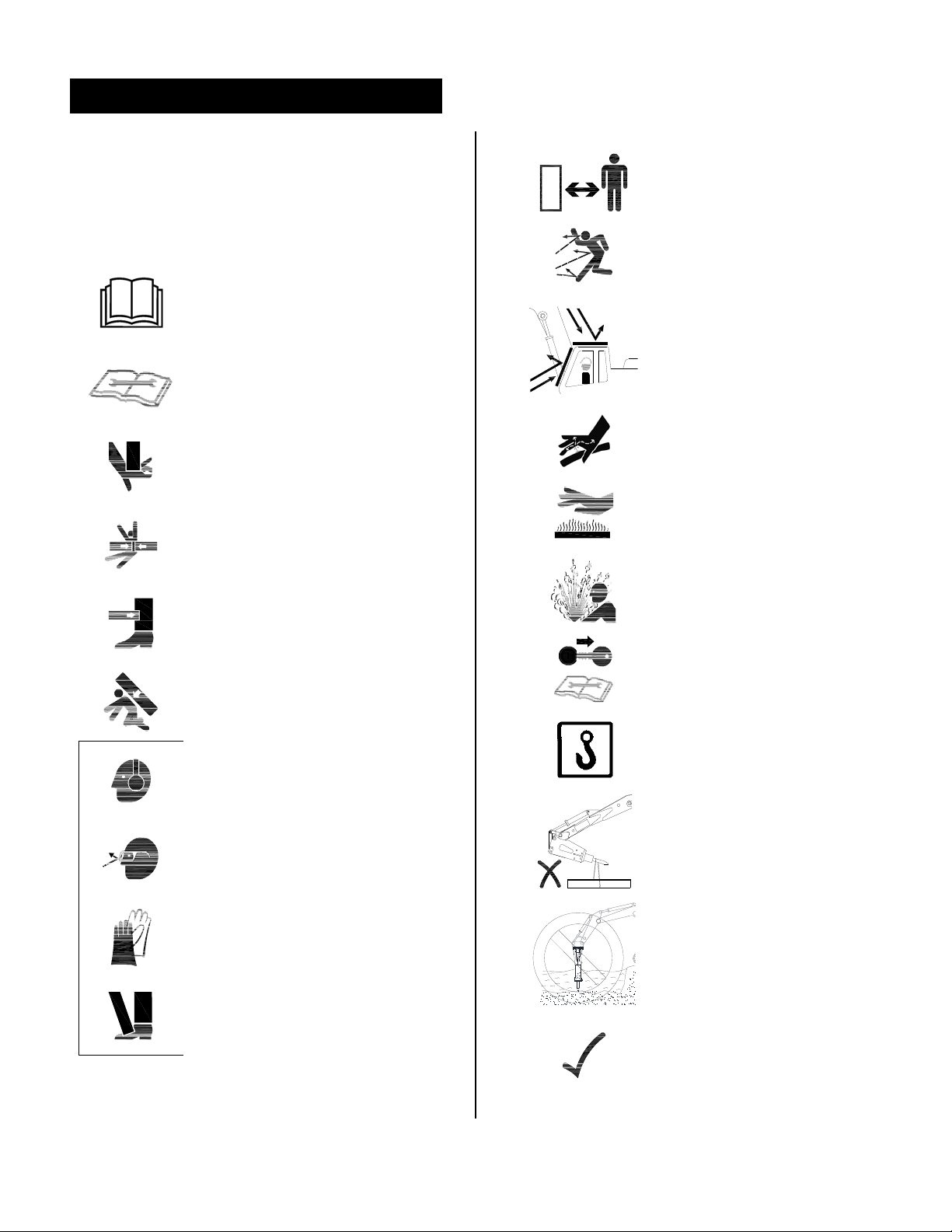
Safety Information – [cont’d]
Qualified Person
For the purposes of this manual, a qualified person
is an individual that has successfully demonstrated
or completed the following:
Has read, fully understands and adheres to all
safety statements in this manual.
Is competent to recognize predictable hazardous
conditions and possess the authorization, skills
and knowledge necessary to take prompt
corrective measures to safeguard against
personal injury and/or property damage.
Has completed adequate training in safe and
proper installation, maintenance and operation
of this Allied equipment.
Is authorized to operate, service and transport
the Allied equipment identified in Table 1.1.
Safety Information Overview
It’s important for all personnel working with the Allied
equipment to read this manual in its entirety. It
includes important safety information intended to
help personnel avoid unsafe practices that may lead
to mishaps. Safety information described at the
beginning of this manual is generic in nature. As you
continue reading through later sections of this
manual, instructions and safety information become
tool-specific and operation-specific.
Allied has made every effort to provide information
as complete and accurate as possible for this
document. Allied cannot anticipate every possible
circumstance that might involve a potential hazard.
The warnings in this manual and labels affixed to the
Allied attachment are therefore not all inclusive.
General Construction Safety
Always follow procedures that promote safe
conditions for workers and bystanders. The standard
safety precautions expected and required of those
working in construction shall include, but not limited
to:
Locating existing underground service and utility
lines
Establishing pedestrian barriers
Using personnel protection equipment
appropriate to working conditions, etc.
Federal, State, Local and OSHA Construction
Guidelines and Regulations
Use the Allied equipment in accordance with all
federal, state and local regulations regarding
construction practices and public safety.
Identification of, and compliance to, governing
regulations are the responsibility of the owner and
operator.
In the United States, comply with the
recommendations of the Occupational Safety and
Health Administration standards of the U.S.
Department of Labor. For OSHA construction
guidelines contact your local federal government
office or write:
U.S. Government Printing Office Superintendent of
Documents P.O. Box 371954 Pittsburgh, Pa. 15250-
7954
Website: www.osha.gov
Ask for Construction Industry OSHA Standards
Stock #869-034-00107-6.
Owner’s Responsibilities
Ensure that only qualified personnel operate and
service the Allied equipment.
Ensure personnel protection equipment is available
to personnel and enforce the use of PPE
Ensure equipment is kept in safe operating condition
Ensure safety-related materials such as instructions
and including this manual are kept in a convenient
location so that they are easily accessible to
operators and maintenance personnel.
Attention Read the Manual
Improper installation, operation or maintenance of
the Allied equipment could result in serious injury or
death. Only qualified operators may operate the
Allied equipment. Personnel responsible for the
maintenance of the Allied equipment or its systems,
including inspection, installation or adjustments must
also be qualified. Operators and personnel
responsible for maintenance of this equipment
should read this manual. Other manuals, such as
those published by the machinery used in support of
the Allied equipment, should also be read.