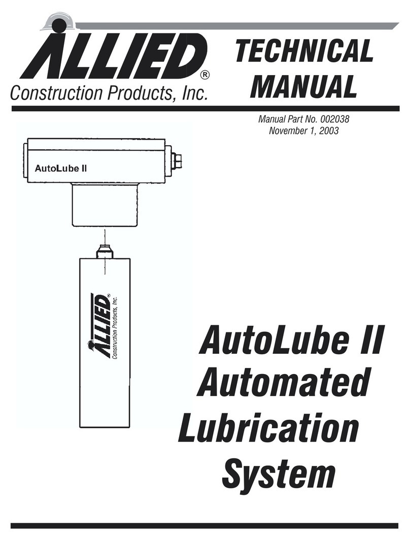
Allied AutoLube III User manual

AutoLube III
Automated
Lubrication
System
Construction Products, LLC
TECHNICAL
MANUAL
Manual Part No. 102782
November 11, 2002

Allied AutoLube III
Allied AutoLube III
Document Change Notice
Date Page Change

Allied AutoLube III
11-11-02 i
TABLE OF CONTENTS
Section Page
SECTION 1.0 INTRODUCTION .............................1
SECTION 2.0 OVERVIEW.................................3
SECTION 3.0 GENERAL CONSTRUCTION SAFETY .................4
3.1 Operator Safety Recommendations ........................4
SECTION 4.0 AUTOLUBE III TECHNICAL SPECIFICATIONS ...........5
SECTION 5.0 THEORY OF OPERATION ........................6
SECTION 6.0 AUTOLUBE III INSTALLATION ....................7
6.1 Installation .....................................7
6.2 Installing the Reservoir Retainer .........................8
SECTION 7.0 AUTOLUBE III OPERATION ......................10
7.1 Follower Seal ...................................10
7.2 Filling Pump with Grease ............................10
7.2.1 Remove Empty Cartridge .........................10
7.2.2 Install Grease Cartridge ..........................11
7.2.3 Air Purging .................................11
7.2.4 Prefill Lubricant Line ...........................11
7.2.5 Manual Bulk Filling .............................11
7.2.6 Manual Filling with Hand Pump .....................12
7.3 Maintenance Before Operation..........................12
7.4 Operation .....................................12
7.4.1 Working In High/Low Temperatures ...................12
7.4.2 Working Underwater ...........................13
SECTION 8.0 TROUBLESHOOTING ..........................14
AutoLube III Inoperable ...............................14
SECTION 9.0 REMOVAL AND STORAGE OF AUTOLUBE III............16
9.1 Mechanical Removal Of AutoLube III ......................16
9.2 Removing Hoses .................................16
9.3 Reattaching AutoLube III After Idle Periods ..................16
SECTION 10.0 PARTS INFORMATION ........................17

Allied AutoLube III
ii 11-11-02
This page intentionally
left blank.

SECTION 1.0
INTRODUCTION
This manual contains important informa-
tion for the safe use and maintenance of the
Allied AutoLube III. Read this manual
thoroughly before installing, operating or
servicing the AutoLube III. The AutoLube
III must be operated, maintained and re-
paired exclusively by persons familiar with
the operating instructions. Operate the
AutoLube III only after safety instructions
and this manual are fully understood. This
manual must be easily accessible to opera-
tors and service personnel. Store this man-
ual in a convenient location.
~Instructions identified with this sym-
bol are important for personnel safety and
full service life of the AutoLube III. Follow
them carefully.
~WARNING
Instructions given inside a WARNING
box emphasize a potentially dangerous
procedure which may result in injury or
death to the operator or any bystanders
in the work area. Please read and fol-
low these instructions carefully and
heed all decals.
~CAUTION
Instructions given inside a CAUTION box
emphasize a procedure that may cause
damage to the equipment if not per-
formed properly. Read these instruc-
tions carefully before performing the
procedure on the Allied AutoLube III
Lubrication System.
This technical manual describes in detail
the procedures needed to operate the Allied
AutoLube III Lubrication System on site.
Pay careful attention to all instructions
and follow all governing regulations. This
pump is exclusively designed to dispense
grease in Hydraulic Hammer applications
and should be operated only with hydraulic
power. Any other use not in accordance
with the instructions will result in loss of
claims for warranty and liability. Opera-
tion or service other than in accordance
with these instructions may subject the
AutoLube III to conditions beyond its de-
sign capability. Improper operation, ser-
vice or the use of non-Allied parts may
result in AutoLube III failure or personnel
injury.
Responsibility for operation and safety lies
at all times with the operator of the carrier.
Allied takes no responsibility for the fol-
lowing:
·Incorrect usage of the AutoLube III.
·Exceeding maximum ratings as pro-
vided in Section 4.0 Specifications.
·Inadequate maintenance of the
AutoLube III.
·Use of non-Allied spare parts.
·Damages due to the use of grease which
is not or is only conditionally pumpable
in a centralized lubrication system.
Allied Chisel Paste is recommended.
·Damage caused by unauthorized modi-
fication of the system components. Con-
tact Allied Technical Service Depart-
ment if modification is necessary.
Allied AutoLube III
11-11-02 1
·Damage caused by insufficient lubri-
cant or irregular pump refilling.
·Damage caused by contaminated lubri-
cants.
·Damage caused by improper disposal of
used or contaminated lubricants.
Allied provides no warranty for the follow-
ing wear parts:
·All seals
·O-rings
·Hoses
Allied AutoLube III
211-11-02

SECTION 2.0
OVERVIEW
The Allied AutoLube III Lubrication Sys-
tem (AutoLube III) is designed to provide a
simple and effective, inexpensive method
of lubricating hydraulic hammers.
The AutoLube III is a fully automated sys-
tem with lubricant supplied by a hydraulic
pump. The AutoLube III is installed and
works integrally with the carrier and ham-
mer, pumping lubricant to the hammer
bushings and demolition tool every time
the hammer is activated. Costly downtime
is eliminated because the right amount of
lubricant is delivered at the right time. The
Allied AutoLube III is the proven solution
for lubricating hydraulic hammers.
The Allied AutoLube III Lubrication Sys-
tem provides the following advantages:
·Simple design
·Compact size - mounts on hammer.
·Supplied with all mounting hardware
and adapter fittings.
·Replaceable or refillable, standard 12
ounce grease cartridge. Bulk filling of
cartridge canbe complete
·No tools required to change grease
cartridge.
·Primer releif valve.
·Adjustable output by changing meter-
ing plug.
·Used with Allied Chisel Paste.
·Lubricant level can be monitored from
operator’s cab.
Figure 2-1 illustrates the AutoLube III
main components and Figure 2-2 shows
typical mounting locations of the
AutoLube III on a hammer. The mounting
location varies with the hammer model.
Allied AutoLube III
11-11-02 3
PUMP
HOUSING
GREASE
Figure 2-1. AutoLube III Main Components
Figure 2-2. Typical AutoLube III Mounting

SECTION 3.0
GENERAL CONSTRUCTION SAFETY
Always follow procedures that promote
safe conditions for workers and by-
standers. This includes, but is not limited
to: locating existing underground utility
services, establishing pedestrian barriers
and wearing personal protective equip-
ment.
~CAUTION
Read and follow all equipment and
machinery instructions.
Comply with all federal and local regula-
tions regarding construction practices and
public safety. Identification of and compli-
ance to governing regulations are the re-
sponsibility of the owner and operator.
In the United States, comply with the rec-
ommendations of the Occupational Safety
and Health Administration standards of
the U.S. Department of Labor. For OSHA
construction guidelines contact your local
federal government office or write:
U.S. Government Printing Office
Superintendent of Documents
P.O. Box 371954
Pittsburgh, Pa. 15250
Ask for Construction Industry OSHA
Standards Stock #869-034-00107-6.
3.1 Operator Safety Recommendations
·This equipment generates very high
grease pressure. Use extreme caution
when operating this equipment as ma-
terial leaks from loose or ruptured com-
ponents can inject fluid through the
skin and into the body causing serious
bodily injury.
·Use adequate protection to prevent
splashing of material onto the skin or
into the eyes.
·If any fluid appears to penetrate the
skin, get emergency medical attention
immediately. Do not treat as a simple
cut. Tell attending physician exactly
what fluid was injected.
·Do not run any hydraulic lines through
the operator’s cab; they may leak or
even burst, injuring the operator.
·Relieve hydraulic oil pressure before
disconnecting or removing existing
lines on the carrier.
·Collect any oil which spills out and dis-
pose of it properly.
When welding as needed to mount the
AutoLube III, the following instructions
must be observed:
·Disconnect all battery cables from the
carrier battery.
·Protect all hydraulic hoses in the imme-
diate vicinity of the point being welded
to prevent danger of fire or damage to
hoses from heat.
To avoid damage to the carrier and/or the
AutoLube III, perform the following daily
inspections.
·Before starting, visually inspect all
hoses, fittings and fasteners for wear
and looseness.
·Check lubricant level inside the car-
tridge. Refer to Section 6.4.
Allied AutoLube III
411-11-02

SECTION 4.0
AUTOLUBE III TECHNICAL SPECIFICATIONS
Weight Empty 16.3 lbs. (7.4kg)
Full 17.3 lbs. (7.8kg)
Hydraulic Inlet Pressure (max.) 5000 psi (345 bar)
Max Inlet Back Pressure 200 psi (13.8 bar)*
Output Pressure (max.) 6500 psi (450 bar)
Output per Stroke 0.018 in3(0.3 cm3)*
Pump Ratio 1.3:1
Grease Reservoir Volume 14.5 oz.
Operating Temperature -10oF to +180oF (-23oCto+80
oC)
*Pressure Relief Valve required if back pressure is higher than 200 psi.
**Pump output can be increased up to 0.072 in.3(1.2 cm3)byreplacingthe
metering plug; refer to Section 7.4.
Metering Plugs
0.018 in.3(0.3 cm3) Part No. 103057 0.060 in.3(1.0 cm3) Part No. 103060
0.036 in.3(0.6 cm3) Part No. 103508 0.072 in.3(1.2 cm3) Part No. 103061
0.048 in.3(0.8 cm3) Part No. 103059
Hose Inside Diameters:
Hydraulic Line 3/8-inch (9.53mm)
Lubricant Line 1/4-inch (6.35mm)
Connecting Threads:
Hydraulic Line SAE #4 (7/16-20 UNF)
Lubricant Line SAE #4 (7/16-20 UNF)
Cartridge: Allied Chisel Paste
See Section 9.0 for ordering information
Allied AutoLube III
11-11-02 5

Allied AutoLube III
611-11-02
Table 4-2. Dimensions of AutoLube III
Letter Dimension
in. (mm)
Decscription
A 14.91 (379) Overall Height
B 8.69 (221) Overall Width
C 3.00 (76) Overall Depth
D 3.00 (76) Cylinder Block Height
E 8.39 (213) Cylinder Block Width
F 5.64 (143) Mounting Hole Location
G 1.50 (38 Low Level Indicator Cap extended
H 1.40 (36) Hydraulic Inlet Location
J .50 (13)
.56 (14)
Lube Outlet Location
K

Allied AutoLube III
11-11-02 7
A
GREASE CARTRIDGE IS
EMPTY WHEN INDICATOR
SHOWN
IS FULLY EXTENDED AS
SAE 4 O-RING PORT
HYDRAULIC INLET
VENT VALVE
SAE 4 O-RING PORT
OR FILL FITTING
LUBE OUTLET
F
E
B
C
H
(*) NOTE:
J
FULLY EXTENDED (*)
D
K
Figure 4-1. AutoLube III Dimension Drawing

Allied AutoLube III
SECTION 5.0
THEORY OF OPERATION
The AutoLube III is used on a hydraulic
hammer to lubricate the wear bushings
and demolition tool automatically every
time the hammer is started.
Each time the hammer is activated, the
pressure from the carrier’s hydraulic sys-
tem activates the pump; the pump makes
one stroke to dispense grease. When the
hammer is stopped, the hydraulic pressure
to the pump drops below 200 psi (14 bar)
and the internal springs (see Figure 5-1) re-
turn the pump plunger to the initial posi-
tion for the next lube cycle. For proper
operation on older HyRams, the inlet hy-
draulic back pressure is higher than 200 psi
(14bar), a pressure relief valve must be in-
stalled.)
When the hammer is activated, grease
flows to the pump and the plunger opens
the grease inlet port. Grease is drawn into
the pump head by the vacuum in the head.
This vacuum and the pressure of the car-
tridge follower spring force the grease into
the lubricant pump line. Refer to Figure
5-2. When the hammer is stopped, the
plunger and the follower spring return to
their initial positions. This process is re-
peated every time the hammer is started
and stopped.
811/11/02
SPRING
RETAINER
PLUNGER
O-RING
SPRING
SPRING
SPRING
Figure 5-1. Plunger and Internal Springs
FOLLOWER
SPRING ROD
Figure 5-2. Follower Spring and Rod

Allied AutoLube III
11-11-02 9
SECTION 6.0
AUTOLUBE III INSTALLATION
The AutoLube III is Hy-Ram Model spe-
cific. It is mounted on a bracket that is
welded to the hammer box. All accessories,
hardware and hoses are included in the
AutoLube III Kit. Section 9.0 lists the
AutoLube III Kit part numbers.
~CAUTION
Nominal inside diameter of the
hydraulic line MUST be at least .375 in.
(9.53mm) and nominal inside diameter
of the lubricant supply line MUST be at
least .25 in. (6.35 mm)
6.1 Installation
(Refer to Figures 6-1 and 6-2.)
Allied recommends mounting the cartridge
housing in the upright position. Allow suf-
ficient space for cartridge removal and re-
placement and for pump servicing. Mount
AutoLube III so that the pump Low Level
Indicator Cap is visible to the carrier opera-
tor for monitoring lubricant level. Refer to
Figure 6-1. Refer to Section 6.x to install
Reservoir Retainer.
WARNING
Disconnect the battery cables to pre-
vent electrical damage before perform-
ing any welding work.
~CAUTION
Shield all hydraulic hoses in the
AutoLube III mounting vicinity during
welding to avoid the risk of fire or dam-
age to the hoses from excessive heat.
1. Determine location for AutoLube III.
Weld mounting bracket in place.
2. Install in AutoLube #4 SAE side of
Items7&8,90degree ellbow,
SAE#4/4MJIC.
4. Remove presure plug from Hammer.
Install M14-1.5 side item 2,
M14-1.5/4MJIC adaptor.
NOTE
Some Hy-Ram Models have a sepa-
rate pressure port for the
AutoLube III on the cylinder head.
This port is marked with a small P.
Other Hy-Ram Models have a pres-
sure port connection in the flange
on the hydraulic pressure inlet
port. This port is marked with a
large P. See Section 9.0 Parts In-
formation for specific Hy-Ram
Model pressure port type.
4.
INDICATOR CAP
LOW LEVEL
TAB
FINGER
Figure 6-1.Low Level Indicator Cap

Remove Grease fittong from Hammer.
Install 4MSPP side od Item 1
4BSBB/4MJIC adaptor:
5. Install 90 degree elbows on hammer ad-
aptors.
·Elbow (3), #4JIC, for lubrication con-
nection.
·Elbow (4), #6JIC, for hydraulic con-
nection.
6. Connect hoses to elbows (refer to Sec-
tion 5.2 for retrofit kit instructions):
·Hose (5), 3/8-inch, for hydraulic line
connection.
·Hose (6), 1/4-inch, for lube supply line
connection.
·
7. Connect hoses to AutoLube III pump
with adapters.
·Adapter (9), #4JIC, for lubrication
connection.
·Adapter (10), #6JIC, for hydraulic
connection.
8. Bolt AutoLube to Bracket with Hard-
ware provided.
9. Refer to Section 7.1 and install Allied
Chisel Paste cartridge into AutoLube III
cartridge housing. The cartridge can be
refilled and re-used.
6.2 Installing the Reservoir Retainer
The reservoir clip has fingers that fit into a
groove at the lower end of the grease car-
tridge housing. When the retainer is tight-
ened, the housing is pulled into the pump
head. Before installing the Reservoir Re-
tainer, ensure that the Grease Cartridge
Allied AutoLube III
10 11/11/02
Connect to Autolube III
pressure port on hammer
port on hammer
Connect to lubrication
8
5
4
21
3
6
7
Vent valve
Figure 6-2. AutoLube III Installation

Housing (28, Figure 10-1) and gasket (27)
are correctly in place. Install grease car-
tridge (Section 7.1) before final adjustment
of the spring clip (1, Figure 6-3).
1. Install the spring clip (1) on the side of
the pump head (2) with plate (3), cap
screws (4) and lock washers (5) as shown
in Figure 6-3.
2. With Grease Housing (6) installed and
tightened as required, adjust the fingers
of the spring clip (1) so that they firmly
retain the housing.
3. Tighten two cap screws (4).
Allied AutoLube III
11-11-02 11
2
6
1
354
Figure 6-3. Reservoir Retainer

SECTION 7.0
AUTOLUBE III OPERATION
~CAUTION
Low Level Indicator Rod extends from
bottom of pump when grease cartridge
is empty. Replace empty cartridge im-
mediately. Do not operate hammer with-
out grease.
Fill Grease Housing when Low Level Indi-
cator Cap extends from bottom of pump.
7.1 Follower Seal
There is a follower seal at the bottom of the
Grease Housing. The seal lip must be di-
rected toward the follower handle for car-
tridge loading. When filling the housing
with grease manually (bulk) or with a hand
pump, the seal must be flipped so the lip is
directed toward the pump head. Refer to
Figure 7-2. The illustration shows the seal
in the cartridge position, seal lip toward
follower handle.
7.2 Filling Pump with Grease
7.2.1 Remove Empty Cartridge
1. Disengage the retaining clip from the
follower handle. Refer to Figure 7-3.
2. Pull finger tab on reservoir retainer to
disengage clip fingers from the housing
groove.
Allied AutoLube III
12 11/11/02
INDICATOR CAP
LOW LEVEL
TAB
FINGER
Figure 7-1. Low Level Indicator Cap FOLLOWER
HANDLE
RETAINER
CUP
Figure 7-3. Follower Handle Retaining Clip
HOUSING
CAP FOLLOWER
ROD
FOLLOWER
SPRING
FOLLOWER
HANDLE
FOLLOWER
GREASE
HOUSING SEAL
Figure 7-2. Cartridge Housing Components

3. Loosen the housing a couple of turns to
break the seal.
4. Pull follower handle until follower rod is
fully extended. Latch the follower rod
groove into slot in the tube cap.
5. Unscrew housing from the pump head.
6. Carefully release the follower handle to
eject the empty cartridge
7. If replacing cartridge, do not remove fol-
lower seal. If manually filling, flip seal
(Section 7.1).
7.2.2 Install Grease Cartridge
1. Turn off hammer.
2. Remove empty cartridge (Section 7.2).
3. Visually check that follower seal is in the
correct position (Figure 7-2).
4. Pull follower rod out and latch.
5. Remove plastic cap from grease car-
tridge and insert cartridge into housing.
6. Remove pull-tab from cartridge.
7. Pull on Reservoir Retainer finger tab
and install housing into pump head.
Screw housing into pump head.
8. Release follower rod.
9. Purge air from pump. Refer to Section 7.4
10.Latch retaining clip over the top of the
follower handle.
7.2.3 Air Purging
1. Engage the follower rod with the fol-
lower by lightly pulling up and rotating
the follower handle. M.P. I don’t under-
stand this. What is the follower?
2. Push down on follower handle while
pressing the button on Vent Valve to
force any air pockets out of pump head.
Refer to Figure 7-4.
3. Wipe excess grease from Vent Valve.
7.2.4 Prefill Lubricant Line
The lubricant line must be filled with lubri-
cant before operation to bleed air from the
line. A hand grease gun can accomplish
this task.
7.2.5 Manual Bulk Filling
1. Pull finger tab on reservoir retainer to
disengage clip fingers from the housing
groove.
2. Loosen the housing a couple of turns to
break the seal.
3. Check that follower seal lip is oriented
toward pump head; refer to Section 7.1.
4. Pack the bottom of the grease housing
with grease to eliminate air pockets.
5. Dip the packed end of the housing about
one inch into bulk container.
Allied AutoLube III
11-11-02 13
LOW LEVEL
INDICATOR CAP
FINGER
TAB
VALVE
VENT
Figure 7-4. Vent Valve

6. Slowly pull follower handle back while
gradually pushing the housing deeper
into the grease.
7. When the follower rod is fully extended,
latch the rod in the housing cap.
8. Wipe excess grease from the outside of
the housing.
9. Pull on Reservoir Retainer finger tab
and install housing into pump head.
Screw housing into pump head.
10.Adjust reservoir retainer as required;
refer to Section 6.2.
11.Latch retaining clip over the top of the
follower handle.
7.2.6 Manual Filling with Hand Pump
NOTE
Lube Fitting 798197 is installed in
place of Vent Valve for filling with a
hand pump.
1. Remove Vent Valve and install Lube
Fitting 798197.
2. Pull finger tab on reservoir retainer to
disengage clip fingers from the housing
groove.
3. Loosen the housing a couple of turns to
break the seal.
4. Check that follower seal lip is oriented
toward pump head; refer to Section 7.1.
5 Engage the follower rod with the fol-
lower by lightly pulling up and rotating
the follower handle.
6. Push filler pump socket onto filler nip-
ple.
7. While filling housing with hand pump,
watch follower rod. When notch on fol-
lower rod is visible, container is full.
8. Disengage follower rod from follower
and push follower rod into housing. Air
purging is not required unless the hous-
ing was removed from the pump head.
7.3 Maintenance Before Operation
~WARNING
Always relieve pressure from the pump
and supply lines before servicing or re-
pairing the pump to avoid injury from in-
jection, splashing fluid or moving parts.
~CAUTION
Always use Allied parts for service and
repair.
1. Tighten all loose fittings.
2. Replace all damaged tubes or hoses.
3. Check the lubricant level in the
AutoLube III. Fill as required.
7.4 Operation
The pump is shipped with metering plug
10357 which delivers minimum grease out-
put of 0.018 in.3(0.3 cm3). The following
metering plugs are included with the
AutoLube III. Change metering plug to
change output.
Metering Plugs
·0.018 in.3(0.3 cm3) Part No. 103057
·0.036 in.3(0.6 cm3) Part No. 103058
·0.048 in.3(0.8 cm3) Part No. 103059
·0.060 in.3(1.0 cm3) Part No. 103060
·0.072 in.3(1.2 cm3) Part No. 103061
Allied AutoLube III
14 11/11/02

7.4.1 Working In High/Low
Temperatures
The AutoLube III is powered by pressur-
ized hydraulic oil from the carrier’s hy-
draulic system. The oil temperature
should never exceed 176oF (80oC), in accor-
dance with the carrier manufacturer’s rec-
ommendations.
When using the AutoLube III with the
Allied hydraulic hammer, the use of Allied
Chisel Paste is recommended. This paste
can be used in a temperature range of 32oF
to 122oF(0oCto50oC). If the system is to be
used in temperatures below freezing, a cold
weather paste must be used. In such cases,
please consult your Allied authorized
dealer’s service department for recom-
mended cold weather pastes.
7.4.2 Working Underwater
The entire AutoLube III and its holder
must remain above the surface of the wa-
ter.
If the entire hammer is to be used under-
water, the AutoLube III must be positioned
high on the carrier stick and the supply
lines lengthened accordingly.
The fittings on the lubricant lines must be
tightened with particular care to avoid
leaks.
For further details on underwater opera-
tion, contact your Allied Technical Service
Department.
Allied AutoLube III
11-11-02 15

SECTION 8.0
TROUBLESHOOTING
~WARNING
Before removing the hydraulic lines,
bleed all hydraulic pressure.
When rectifying faults, observe all
safety regulations.
AutoLube III Inoperable
If the AutoLube III fails to work properly
and the cause cannot be determined from
the following Troubleshooting Chart, con-
tact the Allied Technical Service Depart-
ment for further assistance.
Allied AutoLube III
16 11-11-02
Problem Cause Remedy
No Lubrication at
Lubrication Point
Lubricant cartridge
empty.
Install new cartridge. Section
7.2.2.
Air in lubricant lines. Purge air. Section 7.2.3.
Pressure oil line to
system is blocked.
Open branch from hammer
pressure line (valve block on
boom).
Pressure oil line to
system leaks.
Check fittings and hose: re-
place if necessary and
tighten properly. Refer to
Section 6.0 Installation.
Lubricant line blocked or too
long.
Check hose, replace if nec-
essary (maximum length 15
feet). Perform functional test
with hose uncoupled. Refer
to Section 6.0 Installation.
Lubricant cartridge installed
incorrectly.
Reinstall cartridge
correctly. Section 7.2.2.
Follower seal damaged or
positioned incorrectly.
Check follower seal position.
Replace follower seal if nec-
essary. Section 7.1.
Lube system draws in air. Misalligned or defective Fol-
lower seal or gasket.
Table of contents
Other Allied Lubrication System manuals
Popular Lubrication System manuals by other brands

Whitmore
Whitmore LUBRICURVE ELECTRO 5 Installation & maintenance manual

OEM Tools
OEM Tools 87042 Operating instructions and parts manual

Perma
Perma STAR VARIO Installation and operation

Perma
Perma FLEX PLUS Series operating instructions

Lincoln
Lincoln QLS 311 Installation and operation instructions

Val-Tex
Val-Tex Easy Lube 40-70 operating manual