SKF 501-301-310-S1 User manual

951-170-236-EN
Version 01
24/05/2019
EN
Assembly Instructions
Injection oiler for metering minimum
lubricant quantities 501-301-310-S1
OIL

- 2 -
951-171-236
Version 01
EN
Legal notice
Training courses
In order to provide a maximum of safety and
economic viability, SKF carries out detailed
training courses. It is recommended that the
training courses are attended. For more in-
formation please contact the respective SKF
Service address.
Copyright
© Copyright SKF
All rights reserved.
Warranty
The instructions do not contain any informa-
tion on the warranty. This can be found in
our general terms and conditions.
Disclaimer
The manufacturer shall not be held respon-
sible for damages caused by:
○Non appropriate use
faulty assembly, operation, setting, main-
tenance, repair or accidents
○Use of inappropriate lubricants
○Improper or late response to malfunc-
tions
○Unauthorized modifications of the prod-
uct
○Intent or negligence
○Use of non-original SKF spare parts
○Incorrect planning or layout
Liability for loss or damage resulting from
the use of our products is limited to the
maximum purchase price. Liability for con-
sequential damages of whatever kind is
excluded.
Legal notice
Manufacturer
SKF Lubrication Systems Germany GmbH
e-mail: Lubrication-germany@skf.com
www.skf.com/lubrication
Manufacturer's addresses
Walldorf Facilities
Heinrich-Hertz-Straße 2-8
69190 Walldorf
Germany
Phone: +49 (0) 6227 33-0
Fax: +49 (0) 6227 33-259
Berlin Facilities
Motzener Straße 35/37
12277 Berlin
Germany
Phone +49 (0)30 72002-0
Fax +49 (0)30 72002-111
www.skf.com/lubrication

- 3 -
951-171-236
Version 01
EN
Table of contents
Table of contents
Legal notice .................................................................................................2
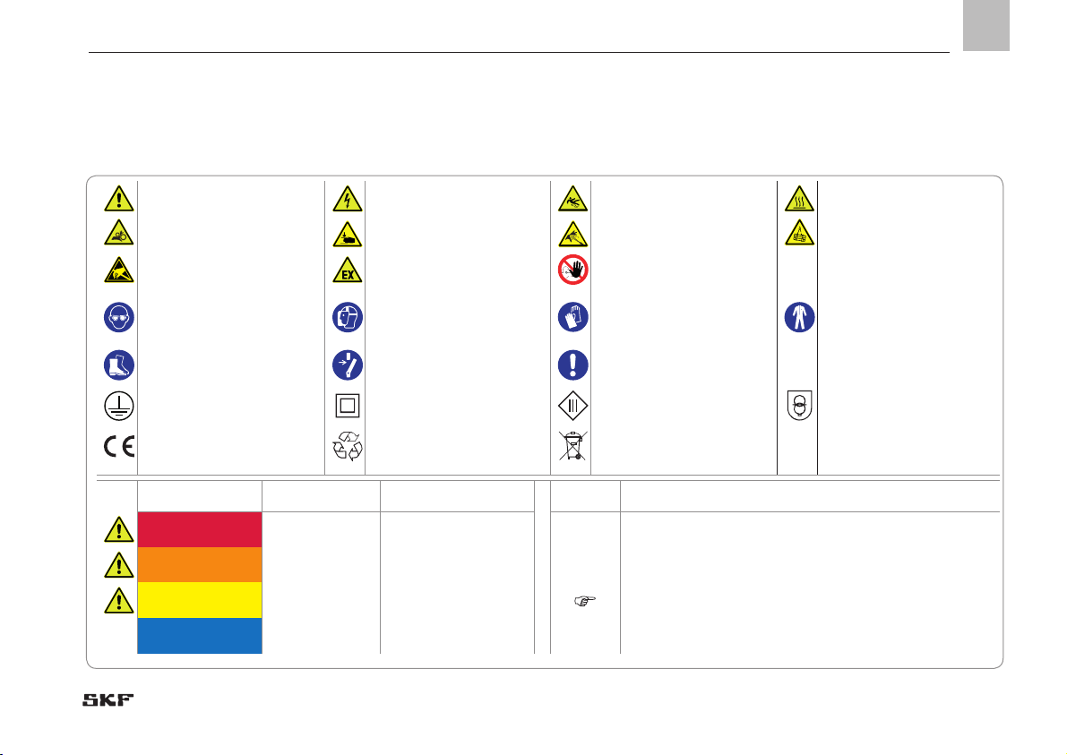
Explanation of symbols, signs and abbreviations........................................5
1. Safety instructions.........................................................................7
1.1 General safety instructions....................................................................7
1.2 General behaviour when handling the product...................................7
1.3 Intended use............................................................................................8
1.4 Foreseeable misuse................................................................................8
1.5 Modifications of the product.................................................................. 8
1.6 Painting of plastic parts.......................................................................... 9
1.7 Reference on Pressure Equipment Directive 2014/68/EU ............... 9
1.8 Inspections prior to delivery ..................................................................9
1.9 Other applicable documents..................................................................9
1.10 Markings on the product........................................................................9
1.11 Persons authorized to operate the pump ..........................................10
1.11.1 Operator.................................................................................................10
1.11.2 Specialist in mechanics ........................................................................10
1.11.3 Specialist in electrics ............................................................................10
1.12 Briefing of external technicians...........................................................10
1.13 Provision of personal protective equipment......................................10
1.14 Operation...............................................................................................10
1.15 Emergency stopping.............................................................................10
1.16 Transport, installation, maintenance, malfunctions, repair,
shutdown, disposal...............................................................................11
1.17 Initial commissioning / daily start-up.................................................12
1.18 Cleaning .................................................................................................12
1.19 Residual risks ........................................................................................13
2. Lubricants................................................................................... 14
2.1 General information .............................................................................14
2.2 Selection of lubricants..........................................................................14
2.3 Material compatibility...........................................................................14
2.4 Temperature characteristics................................................................14
2.5 Ageing of lubricants..............................................................................15
3. Overview, functional description ................................................ 16
4. Technical data ............................................................................. 19
4.1 General technical data..........................................................................19
4.2 Hydraulic connection diagram ............................................................20
5. Delivery, returns, and storage .................................................... 21
5.1 Delivery..................................................................................................21
5.2 Returns .................................................................................................21
5.3 Storage...................................................................................................21
5.4 Storage temperature range.................................................................21
6. Installation.................................................................................. 22
6.1 General information .............................................................................22
6.2 Place of installation...............................................................................22
6.2.1 Minimum assembly dimensions .........................................................23
6.2.2 Installation bores ..................................................................................24
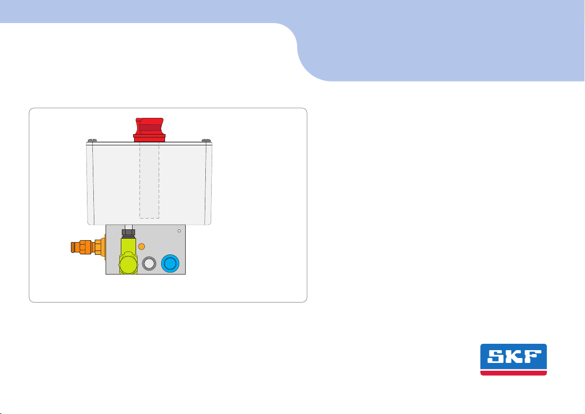
6.2.3 Injection oiler with reservoir................................................................25
6.3 Fill the reservoir ....................................................................................26

- 4 -
951-171-236
Version 01
EN Table of contents
7. Initial start-up ............................................................................ 27
7.1 Inspections prior to initial start-up.....................................................27
7.2 Inspections during initial start-up ......................................................27
8. Operation.................................................................................... 28
9. Cleaning ...................................................................................... 29
9.1 Cleaning agents.....................................................................................29
9.2 Exterior cleaning ...................................................................................29
9.3 Interior cleaning....................................................................................29
10. Maintenance ............................................................................... 30
11. Troubleshooting.......................................................................... 31
12. Repairs........................................................................................ 32
13. Shutdown and disposal............................................................... 33
13.1 Temporary shutdown ...........................................................................33
13.2 Final shutdown and disassembly ........................................................33
13.3 Disposal..................................................................................................33

- 5 -
951-171-236
Version 01
EN
Explanation of symbols, signs and abbreviations
General warning Dangerous electrical voltage Risk of falling Hot surfaces
Unintentional intake Crushing hazard Pressure injection Suspended load
Electrostatically sensitive
components
Potentially explosive
atmosphere
Keep unauthorized persons
away
Wear personal protective
equipment (goggles)
Wear personal protective
equipment (face shield)
Wear personal protective
equipment (gloves)
Wear personal protec-
tive equipment (protective
clothes)
Wear personal protective
equipment (safety shoes)
Disconnect product from
mains General obligation
Protective conductor
(protection class I)
Protection y double or rein-
forced insulation
(protection class II)
Protection by extra low volt-
age (protection class III)
Safe galvanic isolation (pro-
tection class III)
CE marking Disposal, recycling Disposal of waste electrical
and electronic equipment
Warning level Consequence Probability Symbol Meaning
DANGER Death, serious
injury imminent lChronological guidelines
WARNING Death, serious
injury possible ¡Lists
CAUTION Minor injury possible Refers to other facts, causes, or consequences
NOTICE Property damage possible
The following abbreviations may be used within these instructions. Symbols within safety notes mark the kind and source of the hazard.

- 6 -
951-171-236
Version 01
EN Explanation of symbols, signs and abbreviations
Fig. 1 Abbreviations and conversion factors
re. regarding °C degrees Celsius °F degrees Fahrenheit
approx. approximately K Kelvin Oz. ounce
i.e. that is N Newton fl. oz. fluid ounce
poss. possibly h hour in. inch
if appl. if applicable s second psi pounds per square inch
incl. including d day sq. in. square inch
min. minimum Nm Newtonmeter cu. in. cubic inch
max. maximum ml millilitre mph miles per hour
min. minute ml /d millilitre per day rpm revolutions per minute
etc. et cetera cm3cubic centimetre gal. gallon
e.g. for example mm millimetre lb. pound
kW kilowatt l litre hp horse power
U Voltage dB (A) sound pressure level kp kilopond
R resistance > greater than fpsec feet per second
I current < less than conversion factors
V volt ± plus/minus Length 1 mm = 0.03937 in.
Wwatt Ø diametre Area 1 cm² = 0.155 sq.in
AC alternating current kg kilogram Volume 1 ml = 0.0352 fl.oz.
DC direct current rh relative humidity 1 l = 2.11416 pints (US)
A ampere ≈approximately Mass 1 kg = 2.205 lbs
Ah ampere hour = equal to 1 g = 0.03527 oz.
Hz frequency [Hertz] % per cent Density 1 kg/cc = 8.3454 lb./gal.(US)
nc normally closed contact ‰ per mille 1 kg/cc = 0.03613 lb./cu.in.
no normally open contact ≥greater than Force 1 N = 0.10197 kp
N/A not applicable ≤less than Pressure 1 bar = 14.5 psi
ft. feet mm2square millimetre Temperature °C = (°F-32) x 5/9
rpm revolutions per minute Output 1 kW = 1.34109 hp
áIncreases a value Acceleration 1 m/s² = 3.28084 ft./s²
âReduces a value Speed 1 m/s = 3.28084 fpsec.
1 m/s = 2.23694 mph

1
- 7 -
951-171-236
Version 01
EN
1. Safety instructions
1.1 General safety instructions
○The owner must ensure that safety infor-
mation has been read by any persons en-
trusted with works on the product or by
those persons who supervise or instruct
the before-mentioned group of persons.
In addition, the owner must also ensure
that the relevant personnel are fully fa-
miliar with and have understood the con-
tents of the Instructions. It is prohibited to
commission or operate the products prior
to reading the instructions
○These instructions must be kept for fur-
ther use
○The described products were manufac-
tured according to the state of the art.
Risks may, however, arise from a usage
not according to the intended purpose
and may result in harm to persons or
damage to material assets
○Any malfunctions which may affect safety
must be remedied immediately. In addi-
tion to these Instructions, general statu-
tory regulations for accident prevention
and environmental protection must be
observed
1.2 General behaviour when handling the
product
○The product may be used only in aware-
ness of the potential dangers, in proper
technical condition, and according to the
information in these instructions
○Familiarize yourself with the functions
and operation of the product. The speci-
fied assembly and operating steps and
their sequences must be observed
○Any unclear points regarding proper
condition or correct assembly/ operation
must be clarified. Operation is prohibited
until issues have been clarified
○Keep unauthorized persons away
○Wear personal protective equipment
always
○Precautionary operational measures and
instructions for the respective work must
be observed
○Responsibilities for different activities
must be clearly defined and observed.
Uncertainty seriously endangers safety
○Safety-related protective and safety
equipment must not be removed, modi-
fied or affected otherwise in its function
and is to be checked at regular intervals
for completeness and function
○If protective and safety equipment has to
be dismantled, it must be reassembled
immediately after finishing the work, and
then checked for correct function
○Remedy occurring faults in the frame of
responsibilities. Immediately inform your
superior in the case of faults beyond your
competence
○Never use parts of the product as stand-
ing or climbing aids

- 8 -
951-171-236
Version 01
EN 1. Safety instructions
1.3 Intended use
Supply of lubricating oil within the speci-
fications, technical data and limits for the
provision of lubrication points and oiling of
surfaces in the metal-cutting production as
well as the forming and joining technology.
Usage is allowed exclusively for professional
users in the frame of commercial and eco-
nomic activities.
1.4 Foreseeable misuse
Any usage differing from the one stated in
these Instructions is strictly prohibited, par-
ticularly a usage:
○outside the indicated ambient tempera-
ture range
○outside the stated compressed air quality,
the stated pressure range and the volume
flow
○with non-specified means of operation
○without adequate pressure control valve
○in areas with aggressive or corrosive ma-
terials (e.g. high salt concentration)
○of plastic parts in areas with high ozone
levels or in areas with harmful radiation
(e.g. ionising radiation)
○to supply, transport, or store hazardous
substances and mixtures in accordance
with annex I part 2-5 of the CLP regula-
tion (EG 1272/2008) or HCS 29 CFR
1910.1200 marked with GHS01-GHS06
and GHS08 hazard pictograms
○to feed, forward, or store gases, liquefied
gases, dissolved gases, vapours, or fluids
whose vapour pressure exceeds the nor-
mal atmospheric pressure of 1013 mbar
by more than 0.5 bar at the maximum
permissible operating temperature.
○in an explosion protection zone
1.5
Unauthorized conversions or modifica-
tions may result in unforeseeable impacts
on safety. Therefore, any unauthorized
conversions or modifications are expressly
prohibited.

1
- 9 -
951-171-236
Version 01
EN
1. Safety instructions
1.6 Painting of plastic parts
Painting of any plastic parts or seals of the
described products is expressly prohibited.
Remove or tape plastic parts completely be-
fore painting the superior machine
1.7 Reference on Pressure Equipment
Directive
2014/68/EU
Because of its performance data the product
does not achieve the limit values defined in
Article 4 (1) (a) (ii) and is therefore excluded
from the scope of application of Pressure
Equipment Directive 2014/68/EU following
Article 1 (2) (f).
1.8 Inspections prior to delivery
The following inspections were carried out
prior to delivery:
○Safety and functional tests
1.9 Other applicable documents
In addition to these instructions, the fol-
lowing documents must be observed by the
respective target group:
○Operational instructions and approval
rules
○Safety data sheet of the lubricant used
Where appropriate:
○Project planning documents
○Additional information on special ver-
sions. You will find these in the special
system documentation
○Documentation of other components
1.10 Markings on the product
None
Further to the findings of the
workplace risk evaluation the
operating company has to at-
tach additional markings (e. g.
warnings, signs giving orders,
prohibition signs or labelling
as specified by GHS), where
appropriate.

- 10 -
951-171-236
Version 01
EN 1. Safety instructions
1.11 Persons authorized to operate the
pump
1.11.1 Operator
A person who is qualified by training, know-
ledge and experience to carry out the func-
tions and activities related to normal opera-
tion. This includes avoiding possible hazards
that may arise during operation.
1.11.2 Specialist in mechanics
Person with appropriate professional educa-
tion, knowledge and experience to detect
and avoid the hazards that may arise during
transport, installation, start-up, operation,
maintenance, repair and disassembly.
1.11.3 Specialist in electrics
Person with appropriate professional educa-
tion, knowledge and experience to detect
and avoid the hazards that may arise from
electricity.
1.12
Prior to commencing the activities, external
technicians must be informed by the opera-
tor of the company safety provisions, the
applicable accident prevention regulations
to be maintained, and the functions of the
superordinate machine and its protective
devices.
1.13 Provision of personal protective
equipment
The operator must provide suitable personal
protective equipment for the respective
location of operation and the purpose of
operation.
1.14 Operation
The following must be observed during
commissioning and operation:
○Any information within this manual and
the information within the referenced
documents
○All laws and regulations to be complied
with by the user
1.15 Emergency stopping
In case of an emergency stop the pump sta-
tion by:
○Interrupting the compressed air supply
○Where appropriate, using measures
determined by the operator, such as ac-
tuating the emergency stop switch of the
superior machine

1
- 11 -
951-171-236
Version 01
EN
1. Safety instructions
○Undertake drilling at non-critical, non-
load bearing parts only. Use any available
boreholes. Do not damage lines and ca-
bles when drilling.
○Observe possible abrasion points. Protect
the parts accordingly
○Ensure through suitable measures that
movable or detached parts are immobi-
lized during the work and that no limbs
can be caught in between by inadvertent
movements
○Assemble the product only outside of the
operating range of moving parts, at an
adequate distance from sources of heat
or cold. Other units of the machine or ve-
hicle must not be damaged or impaired in
their function by the installation
○Dry or cover wet, slippery surfaces ac-
cordingly
○Cover hot or cold surfaces accordingly
○Work on electrical components must be
carried out by electrical specialists only.
Observe any waiting periods for dis-
charging, if necessary
○Carry out works on electrical components
only while the system is depressurized
and use voltage isolated tools suitable for
electrical works only
1.16 Transport, installation, maintenance,
malfunctions, repair, shutdown,
disposal
○All relevant persons must be informed
of the activity prior to starting any work.
Observe the precautionary operational
measures and work instructions
○Carry out transport using suitable trans-
port and hoisting equipment on suitable
ways only
○Maintenance and repair work can be
subject to restrictions at low or high tem-
peratures (e.g. changed flow properties of
the lubricant). Therefore, where possible,
try to carry out maintenance and repair
work at room temperature.
○Prior to performing work, the product
and the machine, into which the product
will be integrated, must be depressur-
ized and secured against unauthorized
activation

- 12 -
951-171-236
Version 01
EN 1. Safety instructions
1.17 Initial commissioning / daily start-up
Ensure that:
○All safety devices are completely available
and functional
○All connections are correctly connected
○All parts are correctly installed
○All warning labels on the product are
present completely, highly visible and
undamaged
○Illegible or missing warning labels are to
be replaced without delay
○All components used must be designed
according to the maximum operating
pressure and the maximum respectively
minimum ambient temperature
○No parts of the centralized lubrication
system may be subjected to torsion,
shear, or bending
○Check all parts prior to their usage for
contamination and clean, if necessary
○Lubricant lines should be primed with
lubricant prior to installation. This makes
the subsequent ventilation of the system
easier
○Avoid mixing up or wrong assembly of
dismantled parts. Mark these parts ac-
cordingly
1.18 Cleaning
○Risk of fire and explosion when using
inflammable cleaning agents Only use
non-flammable cleaning agents suitable
for the purpose
○Do not use aggressive cleaning agents
○Thoroughly remove residues of cleaning
agents from the product
○Do not use steam jet and high pressure
cleaners
○Mark damp areas accordingly

1
- 13 -
951-171-236
Version 01
EN
1. Safety instructions
1.19 Residual risks
Residual risk Possible in life cycle Prevention/ remedy
Personal injury/ material damage due to
falling of raised parts A B C G H K Keep unauthorized persons away. No people may remain under suspended loads. Lift
parts with adequate lifting devices.
Personal injury/ material damage due to
tilting or falling of the product because of
non-observance of the stated tightening
torques
B C G
Observe the specified tightening torques. Fix the product to components with ad-
equate load-bearing capacities only. If no tightening torques are stated, apply tight-
ening torques according to the screw size characteristics for 8.8 screws.
Personal injury/ damage to material due
to spilled or leaked lubricant B C D F G H K
Be careful when filling the reservoir and when connecting or disconnecting lubricant
feed lines. Always use suitable hydraulic screw connections and lubrication lines
for the stated pressures. Do not mount lubrication lines to moving parts or friction
points. If this cannot be avoided, use spring coils respectively protective conduits.
Life phases:
A = transport, B = installation, C = initial start-up, D = operation, E = cleaning, F = maintenance, G = fault, repair, H = shutdown, K = Disposal

- 14 -
951-171-236
Version 01
EN 2. Lubricants
2. Lubricants
2.1 General information
Lubricants are used specifically for cer-
tain application purposes. In order to fulfil
their tasks, lubricants must fulfil various
requirements.
The most important requirements for lubri-
cants are:
○Reduction of abrasion and wear
○Corrosion protection
○Noise minimisation
○protection against contamination or
penetration of foreign objects
○Cooling (primarily with oils)
○longevity (physical/ chemical stability)
○economic and ecological aspects
2.2 Selection of lubricants
SKF considers lubricants to be an element
of system design. A suitable lubricant is se-
lected already when designing the machine
and forms the basis for the planning of a
centralized lubrication system.
The selection is made by the manufacturer
or operator of the machine, preferably to-
gether with the lubricant supplier based on
the requirement profile defined.
Should you have little or no experience with
the selection of lubricants for centralized lu-
brication systems, please contact SKF.
If required we will be glad to support cus-
tomers to select suitable components for
feeding the selected lubricant and to plan
and design their centralized lubrication
system.
You will avoid possible downtimes through
damage to your machine or system or
damage to the centralized lubrication
system.
2.3 Material compatibility
Lubricants must generally be compatible
with the following materials:
○steel, grey iron, brass, copper, aluminium
○NBR, FPM, ABS, PA, PUR, PETP
2.4 Temperature characteristics
The lubricant used must be suitable for the
specific ambient temperature of the product.
The viscosity required for proper operation
of the product must be adhered to and must
not be exceeded in case of low temperatures
nor fall below specification in case of high
temperatures. Specified viscosities, see
chapter Technical data.

2
- 15 -
951-171-236
Version 01
EN
2. Lubricants
w
Only lubricants specified for the
product (see chapter Technical
data) may be used. Unsuitable
lubricants may lead to a failure of
the product.
Do not mix lubricants. This may
have unforeseeable effects on
the usability and therefore on the
function of the centralized lubri-
cation system.
When handling lubricants the rel-
evant safety data sheets and haz-
ard designations, if any, on the
packaging have to be observed.
2.5 Ageing of lubricants
After a prolonged downtime of the machine,
the lubricant must be inspected prior to
re-commissioning as to whether it is still
suitable for use due to chemical or physical
ageing. We recommend that you undertake
this inspection already after a machine
downtime of 1 week.
If doubts arise as to a further suitability of
the lubricant, please replace it prior to re-
commissioning and, if necessary, undertake
initial lubrication by hand.
It is possible for lubricants to be tested in the
company's laboratory for their suitability for
being pumped in centralized lubrication sys-
tems (e.g. "bleeding").
Please contact SKF. if you have further ques-
tions regarding lubricants.
You may request an overview of the lubri-
cants tested by SKF.
Due to the multitude of possible
additives, individual lubricants,
which according to the manu-
facturer's data sheets fulfil the
necessary specification, may not,
in fact, be suitable for use in cen-
tralized lubrication systems (e. g.
incompatibility between synthetic
lubricants and materials). In
order to avoid this, always use
lubricants tested by SKF.

- 16 -
951-171-236
Version 01
EN 3. Overview, functional description
Fig. 2 Overview, functional description - injection oiler
3. Overview, functional description
The injection oilers described in these in-
structions are pneumatic piston pumps that
dispense lubricating oil in an unchangeable
quantity.
Corresponding to the variant of the injection
oiler, the lubricating oil is supplied either from
the installed reservoir or from a lubricant feed
line to be connected by the operator.
After each activation the injection oilers must
be relieved from pressure to allow the piston to
return into its initial position. The compressed
air is controlled by a way valve to be provided
by the operator.
OIL

3
- 17 -
951-171-236
Version 01
EN
3. Overview, functional description
Reservoir lid (9)
Serves to fill the reservoir with suitable clean
lubricant and as a protection against contami-
nation of the lubricant.
Strainer insert (10)
The strainer insert (500 µm) prevents severely
contaminated lubricating oil from being filled
into the reservoir accidentally.
Reservoir (8)
The lubricant is stored in the reservoir.
Vent line (4)
Vents the metering element during the filling
procedure.
Connection of the lubrication line (1)
Serves to connect the lubrication line Connec-
tion is realized via a push-in type connector (Ø
4 x 0,85)
Fig. 3 Overview, functional description - injection oiler with reservoir
OIL
9
10
8
4
1

- 18 -
951-171-236
Version 01
EN 3. Overview, functional description
Fig. 4 Overview, functional description of injection oiler with reservoir
Venting of the spring chamber (3)
Serves to ventilate the spring chamber during
a piston stroke.
Compressed air connection (2)
Serves to connect the compressed air line.
Fastening bores (5)
The fastening bores on the bottom side (also
see minimum installation dimensions) of the
metering element serve to fasten the injection
oiler to variants without mounting plate.
OIL
2
3
5

EN
4. Technical data
4
- 19 -
951-171-236
Version 01
4. Technical data
4.1 General technical data
Ambient temperature -20 °C to +80 °C
Operating viscosity 20 - 1100 mm2/s
Inlet air pressure 3 - 8 bar
Volumetric flow rate max. 200 l per minute at 6 bar
Protection against too high pressures Pressure control valve 10 bar
Compressed air quality according to
ISO 8573 ≤ Class 5
Air inlet G1/8
sound pressure level < 70 dB (A)
Output volume 3.0 mm3 / stroke ± 20 %
Adjustable flow rate NO
Number of outlets 1
Number of lubrication pulses max. 120 per minute
Installation position Reservoir on top, as illustrated
Nominal volume of reservoir 0.25 l
Empty weight 0.48 kg
OIL

EN 4. Technical data
- 20 -
951-171-236
Version 01
4.2 Hydraulic connection diagram
Table of contents
Other SKF Lubrication System manuals

SKF
SKF TLGU 10 User manual

SKF
SKF HTL201 EEX User manual

SKF
SKF LINCOLN ATEX PSG1 Series User manual

SKF
SKF HS04 User manual

SKF
SKF LUBRILEAN Basic User manual

SKF
SKF UFD20 Series User manual

SKF
SKF LINCOLN P203 User manual

SKF
SKF LUBRILEAN Vario User manual

SKF
SKF TLAC 50/B User manual

SKF
SKF CLU5 User manual

SKF
SKF VSG Series User manual

SKF
SKF Lincoln COBRA 1X-R2 User manual

SKF
SKF TLMR User manual

SKF
SKF LINKOLN A Series User manual

SKF
SKF LAGD 60/U User manual

SKF
SKF KGF Series Configuration guide

SKF
SKF 729101/300MP User manual

SKF
SKF TLMR 101 User manual

SKF
SKF OLA Series User manual

SKF
SKF LINCOLN ZPU 01 Version E User manual