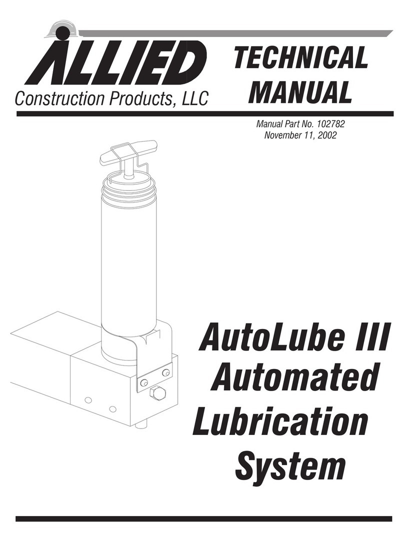
Allied AutoLube II User manual

AutoLube II
Automated
Lubrication
System
Construction Products, Inc.
TECHNICAL
MANUAL
Manual Part No. 002038
November 1, 2003

Allied AutoLube II
Allied AutoLube II
Document Change Notice
Date Page Change
11-30-98 11 Added Installation Of Model
770 Series
11-30-98 19 Added Pressure Port
Locations by Model
8-13-99 3 Art and Text
8-13-99 9,19 Text-Added Hammer Models
3-15-00 3,10,11 Art
3-15-00 3,9,13 Text
3-15-00 7,19 Updated Part No’s.
7-19-01 throughtout Minor editting
7-19-01 19 Revised part numbers
Added 797B and 805B
4-12-02 22,23 Added Seal Kit
4-12-02
10-23-02
4-16-03
11-1-03
9,10
9,10
19
9
Corrected JIC fitting sizes
Added parts information
Text

Allied AutoLube II
11/1/03 i
Table Of Contents
Section Page
SECTION 1.0 INTRODUCTION ............................. 1
SECTION 2.0 OVERVIEW ................................ 3
SECTION 3.0 GENERAL CONSTRUCTION SAFETY .................5
SECTION 4.0 TECHNICAL SPECIFICATIONS .................... 7
SECTION 5.0 AUTOLUBE II INSTALLATION .................... 9
5.1 INSTALLATION ................................. 9
5.2 RETROFIT KIT ................................. 10
5.3 MODEL 770CS INSTALLATION ........................ 11
SECTION 6.0 AUTOLUBE II OPERATION ...................... 13
6.1 THEORY OF OPERATION ........................... 13
6.2 LOADING A CARTRIDGE IN AUTOLUBE II .................13
6.3 PREFILLING THE LUBRICANT LINE .................... 13
6.4 MAINTENANCE BEFORE OPERATION ...................13
6.5 OPERATION ................................... 13
6.6 WORKING IN HIGH/LOW TEMPERATURES ................14
6.7 WORKING UNDERWATER........................... 14
SECTION 7.0 TROUBLESHOOTING ......................... 15
7.1 AUTOLUBE II INOPERABLE ......................... 16
7.2 MANUAL LUBRICATION ........................... 16
SECTION 8.0 REMOVAL AND STORAGE OF AUTOLUBE II............17
SECTION 9.0 PARTS INFORMATION ........................ 19

Allied AutoLube II
ii 11/1/03
This page intentionally
left blank.

SECTION 1.0
INTRODUCTION
This manual contains important informa-
tion for the safe use and maintenance of
the Allied AutoLube II. Read this manual
thoroughly before installing, operating or
servicing the AutoLube II. This manual
must be easily accessible to operators and
service personnel. Store this manual in a
convenient location.
~Instructions identified with this sym-
bol are important for personnel safety and
full service life of the AutoLube II. Follow
them carefully.
~WARNING
Instructions given inside a WARNING
box emphasize a potentially dangerous
procedure which may result in injury or
death to the operator or any bystanders
in the work area. Please read and fol-
low these instructions carefully and
heed all decals.
~CAUTION
Instructions given inside a CAUTION box
emphasize a procedure that may cause
damage to the equipment if not per-
formed properly. Read these instruc-
tions carefully before performing the
procedure on the Allied AutoLube II
Lubrication System.
This technical manual describes in detail
the procedures needed to operate the Allied
AutoLube II Lubrication System. Pay care-
ful attention to all instructions and follow
all governing regulations. Operation or
service other than in accordance with these
instructions may subject the AutoLube II
to conditions beyond its design capability.
Improper operation, service or the use of
non-Allied parts may result in AutoLube II
failure or personnel injury.
Responsibility for operation and safety lies
at all times with the operator of the carrier.
Allied takes no responsibility for the fol-
lowing:
·Incorrect usage of the Autolube II.
·Improper handling of the Autolube II.
·Inadequate maintenance of the
Autolube II.
·Use of non-Allied spare parts.
Allied provides no warranty for the follow-
ing wear parts:
·All seals
·O-rings
·Seal collar
·Hoses
Allied AutoLube II
11/1/03 1

Allied AutoLube II
211/1/03
This page intentionally
left blank.

SECTION 2.0
OVERVIEW
The Allied Autolube II Lubrication System
is a maintenance unit for Allied hydraulic
hammers and provides semi-continuous
lubrication to the hammer demolition tool
and bushings.
The Allied Autolube II Lubrication System
provides the following advantages:
·Simple design - one moving part.
·Compact size - mounts on hammer.
·Replaceable or refillable grease
cartridge.
·No tools required to change grease
cartridge.
·Self priming.
·Adjustable output.
·Can be used with Allied Chisel Paste.
·Lubricant level can be monitored from
operator’s cab.
Figure 2-1 illustrates the AutoLube II
main components and Figure 2-2 shows
typical mounting locations of the
AutoLube II on a hammer. The mounting
location varies with the hammer model.
Allied AutoLube II
11/1/03 3
Lubricant
Cartridge
Pump
View A-A
A
A
Manual
G
rease
Fitting
Figure 2-1. AutoLube II Main Components
Figure 2-2. Typical AutoLube II Mounting

Allied AutoLube II
411/1/03
This page intentionally
left blank.

SECTION 3.0
GENERAL CONSTRUCTION SAFETY
Always follow procedures that promote
safe conditions for workers and
bystanders. This includes, but is not lim-
ited to: locating existing underground util-
ity services, establishing pedestrian
barriers and wearing personal protective
equipment.
~CAUTION
Read and follow all equipment and
machinery instructions.
Comply with all federal and local regula-
tions regarding construction practices and
public safety. Identification of and compli-
ance to governing regulations are the re-
sponsibility of the owner and operator.
In the United States, comply with the rec-
ommendations of the Occupational Safety
and Health Administration standards of
the U.S. Department of Labor. For OSHA
construction guidelines contact your local
federal government office or write:
U.S. Government Printing Office
Superintendent of Documents
P.O. Box 371954
Pittsburgh, Pa. 15250
Ask for Construction Industry OSHA
Standards Stock #869-034-00107-6.
3.1 OPERATOR SAFETY
RECOMMENDATIONS
·Do not run any hydraulic lines through
the operator’s cab; they may leak or even
burst, injuring the operator.
·Relieve hydraulic oil pressure before dis-
connecting or removing existing lines on
the carrier.
·Collect any oil which spills out and dis-
pose of it properly.
When welding as needed to mount the
Autolube II, the following instructions
must be observed:
·Disconnect all battery cables from the
carrier battery.
·Protect all hydraulic hoses in the imme-
diate vicinity of the point being welded to
prevent danger of fire or damage to hoses
from heat.
To avoid damage to the carrier and/or the
AutoLube II, perform the following daily
inspections.
·Before starting, visually inspect all
hoses, fittings and fasteners for wear and
looseness.
·Check lubricant level inside the car-
tridge. Refer to Section 6.4.
Allied AutoLube II
11/1/03 5
Allied AutoLube II
611/1/03
This page intentionally
left blank.

SECTION 4.0
TECHNICAL SPECIFICATIONS
AutoLube II
Weight 12 lbs. ( 26 kg)
Height 3.5 in. ( 89 mm)
Width 7 in. (178 mm)
Length 12 in. (305 mm)
Oil pressure (min.) 1450 psi (100 bar)
Flow rate Adjustable
Hose Inside Diameters:
Hydraulic Line .236 in. (6 mm)
Lubricant Line .314 in. (8 mm)
Connecting Threads:
Hydraulic Line M14 x 1.5
Lubricant Line 04 BSPP
Cartridge: Allied Chisel Paste
NOTE:
The use of Allied Chisel Paste will extend bushing and tool life of the hammers. It is spe-
cially formulated with copper/graphite ingredients that distinguish it from other lubricants
on the market. Allied Chisel Paste provides superior and longer lasting lubrication proper-
ties over a wide range of operating temperatures. Ordering information:
Allied Part No.
100059 Case (12 Tubes)
100060 Box (36 Tubes)
676698 Keg (35 lbs.)
679968 Keg (120 lbs.)
Allied AutoLube II
11/1/03 7

Allied AutoLube II
811/1/03
This page intentionally
left blank.

SECTION 5.0
AUTOLUBE II INSTALLATION
~WARNING
Disconnect the battery cables to pre-
vent electrical damage before perform-
ing any welding work.
~CAUTION
Shield all hydraulic hoses in the
AutoLube II mounting vicinity during
welding to avoid the risk of fire or dam-
age to the hoses from excessive heat.
The AutoLube II is Hy-Ram Model specific
for the newer Hy-Rams. Models 750 and
770 Hy-Rams have a slot burned out in the
hammer box to which the AutoLube II is
mounted with a clamp. All other models
are mounted on a bracket that is welded to
the hammer box. All accessories, hardware
and hoses are included in the AutoLube II
Kit. Section 9.0 lists the AutoLube II Kit
part numbers. Each kit also has a drawing
specific to that model.
~CAUTION
Nominal inside diameter of the
hydraulic line MUST be at least .23 in.
(6 mm) and nominal inside diameter of
the lubricant supply line MUST be at
least .16 in. (4 mm)
5.1 INSTALLATION
(Refer to Figure 5-1.)
1. On models with a mounting bracket,
weld mounting bracket in place.
2. Remove lubricating nipple from ham-
mer lubrication port and install adapter
(1).
3. Remove plug from AutoLube II hydrau-
lic pressure port on hammer and install
adapter (2).
NOTE
Some Hy-Ram Models have a sepa-
rate pressure port for the AutoLube
II on the cylinder head. This port is
marked with a small P. Other
Hy-Ram Models have a pressure
port connection in the flange on the
hydraulic pressure inlet port. This
port is marked with a large P.See
Section 9.0 Parts Information for
specific HyRam Model pressure port
type.
4. Install 90oelbows on adapters:
·Elbow (3), #4JIC, for lubrication con-
nection.
·Elbow (4), #6JIC, for hydraulic con-
nection.
5. Connect hoses to elbows (refer to Sec-
tion 5.2 for retrofit kit instructions):
·Hose (5), 1/4-inch, for lubrication con-
nection.
·Hose (6), 3/8-inch, for hydraulic con-
nection.
Allied AutoLube II
11/1/03 9

6. Bolt AutoLube II to hammer with
M12-1.75 bolts and M12 lock washers:
·On models with bracket, bolt
AutoLube II to bracket.
·On models with slot in hammer box,
slide clamp plate over hoses and posi-
tion clamp plate on the inside of the
box aligning it with the slot. Install
bolts through clamp plate, box, and
AutoLube II.
7. Connect hoses to AutoLube II pump
with adapters and 90oelbows:
·Elbow (7), #4JIC, for lubrication con-
nection.
·Elbow (8), #6JIC, for hydraulic con-
nection.
·Adapter (9), #4JIC, for lubrication
connection.
·Adapter (10), #6JIC, for hydraulic
connection.
8. Prime AutoLube II pump with a
hand-held grease gun at lubrication fit-
tingonpump.
9. Screw Allied Chisel Paste cartridge into
AutoLube II pump. The cartridge can be
refilled and re-used.
5.2 RETROFIT KIT
1. On retrofit kit installations, cut hose to
length and install re-usable fittings (not
shown).
2. Install #4JIC re-usable fitting into el-
bow (7) for lubrication connection.
3. Install #6JIC re-usable fitting into el-
bow (8) for pressure connection.
4. Install adapter (10) into hammer hy-
draulic pressure hose. A check valve is
supplied in the hose for this connection.
Allied AutoLube II
10 11/1/03
Lube
(Stamped CL)
Pressure
(Stamped P)
12
3
4
5
6
8
10
7
9
Connect to Autolube II
pressure port on Hy-Ram
Connect to lubrication port
on Hy-Ram
Figure 5-1. AutoLube II Installation

5.3 MODEL 770CS INSTALLATION
Model 770CS Hy-Ram does not have a pres-
sure-reducing circuit. When the AutoLube
II is installed, additional fittings and a
third hose must be installed to reduce pres-
sure, as follows:
1. The lubrication fittings and mounting
configurations are installed the same as
described in Section 5.1.
2. Remove plug from AutoLube II hydrau-
lic pressure port on hammer, marked
with a small Pon the cylinder head, and
install adapter (2), M14-1.5 x 4BSPP.
3. Install side port of tee fitting (4) on
adapter (2), 04JIC.
4. Connect small hose (6), 04JIC, ¼ inch,
for hydraulic connection to AutoLube II
on the bottom port of tee fitting (4),
04JIC.
5. Connect hose (11), 04-06JIC , to top port
of tee fitting (4), 04JIC..
6. Install tee fitting (12), 04BSPP-06 male
JIC, bottom port, on Connection F,
two-speed connection, on cylinder head.
7. Cap the top port of the tee fitting (12),
04BSPP-06 male JIC or install
two-speed line.
8. Install hose (11), 04-06JIC on orifice
side of tee fitting (12), 04BSPP-06 male
JIC.
9. Proceed with installation at Step 6 in
Section 5.1.
Allied AutoLube II
11/1/03 11
Lube Pressure
910
7
8
5
6
4
2
3
1Connect to Autolube II
pressure port on Hy-Ram
Connect to lubrication port
on Hy-Ram
12
11
To 2-Speed Port
Figure 5-2. AutoLube II Installation on Model 770CS

Allied AutoLube II
12 11/1/03
This page intentionally
left blank.

SECTION 6.0
AUTOLUBE II OPERATION
6.1 THEORY OF OPERATION
The AutoLube II is used on a hydraulic
hammer to lubricate the wear bushings
and demolition tool automatically every
time the hammer is started.
Each time the hammer is activated, the
pressure from the carrier’s hydraulic sys-
tem acts on the slide piston in the pump
housing. A vacuum is created by the slide
piston which pulls lubricant from the car-
tridge into the pump housing where it fills
the pump chamber between the slide pis-
ton and the check valve.
The stroke of the slide piston presses the
lubricant through the check valve into the
lubricant line.
When the hammer is stopped, the slide pis-
ton is pushed back into its initial position
by the spring. Once again, the vacuum that
is created pulls lubricant into the pump
chamber. This process is repeated every
time the hammer is started and stopped.
6.2 LOADING A CARTRIDGE IN
AUTOLUBE II
1. Turn off hammer.
2. Unscrew used cartridge.
3. Screw in new or refilled cartridge.
6.3 PREFILLING THE LUBRICANT LINE
The lubricant line must be filled with lubri-
cant before operation to bleed air from the
line.
1. Using a hand-held grease gun, prefill the
lubrication lines through the lube fitting
provided on the pump housing.
2. To check that line is full, remove the
hose at the hammer hydraulic connec-
tion and observe that lubricant emerges
from the end of the hose.
6.4 MAINTENANCE BEFORE OPERATION
1. Tighten all loose fittings.
2. Replace all damaged tubes or hoses.
3. Check the lubricant level in the
AutoLube II. If the cartridge piston is
not visible, the cartridge is empty. Refer
to Section 6.2 Loading a Cartridge in
AutoLube II.
4. Adjust lock nut and adjusting stem as
necessary; refer to Section 6.5 below.
6.5 OPERATION
~CAUTION
The Check Valve, Lock Nut and Adjust-
ment Stem can become loose from
hammer vibration. Apply LOCTITE remov-
able thread locking compound to the ad-
justment stem after the correct
lubricant delivery has been established,
before tightening the lock nut.
NOTE
The AutoLube II is set to “lowest
delivery/stroke” when shipped.
The lubricant delivery rate can be
adjusted as explained in the follow-
ing paragraphs.
The amount of lubricant supplied to the lu-
bricating point in the tool holder is con-
trolled by the stroke setting on the slide
piston. This amount of lubricant is forced
into the tool holder when the hammer is
Allied AutoLube II
11/1/03 13

started and stopped. The length of the slide
piston stroke and the amount of lubricant
delivered can be adjusted with the adjust-
ment stem as follows:
·If lubricant emerges from the lower wear
bushing during operation, the AutoLube
II slide piston stroke is too long and
forces too much lubricant into the tool
holder.
1. Loosen lock nut.
2. ScrewadjustmentstemINuntil
amount of lubricant per stroke is at
the correct level.
3. Apply LOCTITE removable thread
locking compound to the adjustment
stem after the correct lubricant deliv-
ery has been established, before
tightening the lock nut.
4. Tighten lock nut when properly set.
·If dry areas are observed on the demoli-
tion tool during operation, the AutoLube
II slide piston stroke is too short, deliver-
ing too low an amount of lubricant.
1. Loosen lock nut.
2. Screw adjustment stem OUT until
amount of lubricant per stroke is at
the correct level.
3. Apply LOCTITE removable thread
locking compound to the adjustment
stem after the correct lubricant deliv-
ery has been established, before
tightening the lock nut.
4. Tighten lock nut when properly set.
6.6 WORKING IN HIGH/LOW
TEMPERATURES
The AutoLube II is powered by pressurized
hydraulic oil from the carrier’s hydraulic
system. The oil temperature should never
exceed 176oF (80oC), in accordance with
the carrier manufacturer’s recommenda-
tions.
When using the Autolube II with the Allied
hydraulic hammer, the use of Allied Chisel
Paste is recommended. This paste can be
used in a temperature range of 32oFto
122oF(0
oCto50
oC). If the system is to be
used in temperatures below freezing, a cold
weather paste must be used. In such cases,
please consult your Allied authorized
dealer’s service department for recom-
mended cold weather pastes.
6.7 WORKING UNDERWATER
The entire AutoLube II and its holder must
remain above the surface of the water.
If the entire hammer is to be used under-
water, the Autolube II must be positioned
high on the carrier stick and the supply
lines lengthened accordingly.
The fittings on the lubricant lines must be
tightened with particular care to avoid
leaks.
For further details on underwater opera-
tion, contact your Allied Technical Service
Department.
Allied AutoLube II
14 11/1/03
Lock Nut
Adjusting
Screw
Pump
Body
Manual
Grease Fitting
Figure 6-1. Lubricant Adjusting Stem

SECTION 7.0
TROUBLESHOOTING
~WARNING
Before removing the hydraulic lines,
bleed all hydraulic pressure.
When rectifying faults, observe all
safety regulations.
Allied AutoLube II
11/1/03 15
Problem Cause Remedy
No Lubrication at
Lubrication Point
Lubricant cartridge
empty.
Install new cartridge.
Air in lubricant lines. Bleed system of air
(refer to Section 6.3).
Pressure oil line to
system is blocked.
Open branch from ham-
mer pressure line (valve
block on boom).
Pressure oil line to
system leaks.
Check fittings and hose:
replace if necessary and
tighten properly.
Lubricant line blocked or
too long.
Check hose, replace if
necessary (maximum
length 15 feet). Perform
functional test with hose
uncoupled.
Lubricant cartridge in-
stalled incorrectly.
Reinstall cartridge
correctly (refer to Section
6.2); check sealing sleeve,
replace if necessary.
Lube system draws in air. Seal between cartridge
and pump housing defec-
tive. Replace seal.
Check valve in pump
housing defective.
Replace check valve.

TROUBLESHOOTING (cont’)
7.1 AUTOLUBE II INOPERABLE
If the AutoLube II fails to work properly
and the cause cannot be determined, con-
tact your Allied Technical Service Depart-
ment for further assistance.
7.2 MANUAL LUBRICATION
There are two ways to lubricate the demoli-
tion tool if the AutoLube II is out of service:
·Lubricate through the lubricating nipple
using a hand-held grease gun.
·Move lubricating nipple from AutoLube
II to hammer as follows:
1. Unscrew the lubricant line from the
hammer connection.
2. Remove lubricating nipple from the
AutoLube II.
3. Screw lubricating nipple directly into
hammer connection.
4. Lubricate using a hand-held grease
gun.
Allied AutoLube II
16 11/1/03
Problem Cause Remedy
Lubricant Supply too Low. Piston stroke set too short. Adjust piston stroke (refer to
Section 6.5).
Lubricant Supply too High Piston stroke set too long. Adjust piston stroke (refer to
Section 6.5).
Lubricant Supply Incorrect Wrong type of lubricant. Observe lubricant recom-
mendations.
Table of contents
Other Allied Lubrication System manuals
Popular Lubrication System manuals by other brands

Perma
Perma Classic 120 operating instructions

perma-tec
perma-tec NOVA 125 operating instructions

Perma
Perma Star Control Time operating instructions

DROPSA
DROPSA MiQueL EXT User Operating and Maintenance Manual

Wittenstein Alpha
Wittenstein Alpha LUC+400 operating manual

Bijur Delimon
Bijur Delimon SG-A Operating instruction