Allied H12E User manual

P/N 599049W Printed in U.S.A. 4/7/2020
Hydraulic Winch
Please check the Allied Systems website
regularly for updates to this manual.
www.alliedsystems.com
A Product of
Sherwood, OR USA
Service Manual
H12E

Safety Precautions
Read, understand and observe the Safety Summary
on pages 0-3 through 0-5
to prevent injury to personnel and damage to equipment.
Winch serial number _________________________
Date put into service _________________________
NOTE: This publication may be translated to different languages for sole purpose
of easy reference in non-English speaking locations.
Should there be differences in interpretations to the text,
please refer to the English language edition published by Allied Systems Company
as the controlling document.

i
Safety Summary
General Safety Notices
The following pages contain general safety warnings
which supplement specific warnings and cautions
appearing elsewhere in this manual. All electrical and
hydraulic equipment is dangerous. You must thoroughly
review and understand the Safety Summary before
attempting to operate, troubleshoot or service this winch.
The following symbols and terms are used to emphasize
safety precautions and notices in this manual:
The “DANGER” symbol indicates a
hazardous situation which, if not avoided,
will result in serious injury or death.
Carefully read the message that follows
to prevent serious injury or death.
The “WARNING” symbol appears
wherever incorrect operating procedures
or practices could cause serious injury
or death. Carefully read the message that
follows to prevent serious injury or death.
The “CAUTION” symbol appears where a
hazardous situation which, if not avoided,
could result in minor to moderate injury
and equipment damage.
NOTICE
This signal word alerts to a situation that
is not related to personal injury but may
cause equipment damage.
NOTE: …
The term “NOTE” highlights operating
procedures or practices that may improve
equipment reliability and/or personnel
performance.
NOTE: All possible safety hazards cannot
be foreseen so as to be included in this
manual. Therefore, you must always
be alert to potential hazards that could
endanger personnel and/or damage the
equipment.
Safety Regulations
Each country has its own safety legislation. It is in the
operator’s own interest to be conversant with these
regulations and to comply with them in full. This also
applies to local bylaws and regulations in force on a
particular worksite.
Should the recommendations in this manual deviate from
those in the user’ country, the national regulations should
be followed.
Operation, Inspection, and Maintenance Warnings
Obey the following cautions and warnings
before using your winch to avoid equipment
damage, personal injury or death.
• Do not operate the winch unless your are authorized
and trained to do so.
• Do not operate the winch unless the vehicle is
equipped with a screen to protect the operator if
the wire rope breaks.
• Read, understand, and follow the operating,
inspection, and maintenance instructions in this
manual.
• Do not use the control levers for hand holds when
entering or leaving the vehicle.
• Do not permit other people near the control area
when you inspect or repair a machine.
• Never inspect, repair, or perform maintenance on
a machine that is in motion.
Safety Summary

ii
• Inspect the winch before each use:
»Make sure that the controls and instruments
operate correctly.
»Report the need for repairs immediately.
»Do not work with a damaged or worn wire rope.
»Do not use a winch that needs repairs.
»If the wire rope and ferrule must be removed
from the drum, make sure the end of the
wire rope and ferrule are controlled when
the ferrule is released. The end of the wire
rope can suddenly move from the drum like
a compressed spring when the ferrule is
released, and cause an injury.
• Stay in the operator’s seat when operating the
winch.
• Do not stand on the vehicle when operating the
winch.
• Avoid winch operation near people or other
machines.
• Never stand nor permit others to stand in the bight
(loop) of a wire rope.
• Do not stand nor permit others to be near the winch
or wire rope when there is tension on the wire rope.
• Observe jobsite rules.
• Be in complete control at all times.
• Do not use the control levers as hangers for clothes,
water bags, grease guns, lunch pails, etc.
• Do not leave the vehicle when the winch wire rope
is under tension.
• Do not permit riders on the vehicle or load.
• Do not use the winch as an anchor for a double or
two-part line.
• Do not pull the hook through the throat or over the
drum, which will cause damage.
• When the winch is not in use, make sure the control
lever is in BRAKE-ON position and the winch brake
is applied.
• Do not use winch as a hoist. Tractor and skidder
mounted winches are designed for towing.
• Always inspect wire rope, tail chain and other rigging
components for wear, damage, broken strands or
abuse before use.
• Never use wire rope, tail chain or other rigging that
is worn-out, damaged or abused.
• Never overload wire rope, tail chain or rigging.
• Wire rope and tail chain will fail if worn-out,
overloaded, misused, damaged, improperly
maintained or abused. Wire rope or tail chain failure
may cause serious injury or death!
KG
KG
KG
KG
• Do not terminate wire rope to tail chain by the use
of a knot.
• Do not handle wire rope if the hook end is not free.
A load could break away, suddenly tensioning the
wire rope, resulting in serious injury or death.
• Stay clear of wire rope entry areas (fairlead or arch
rollers, winch drum etc).
• Make sure ground personnel are in plain view of the
operator, and at a distance of at least 1½ times the
working length of the wire rope.

iii
Safety Summary
• Make sure that any hand signals used by ground
personnel are clearly defined and understood by
everyone involved.
• Do not attempt to “jerk” or “shock” a load free. Doing
so can cause loads in excess of the rated capacity
of the wire rope, winch, or mounting hardware.
• Replace any parts only with genuine Allied Winch
parts. Refer to Parts Manual 599048W.
• Maintain a minimum of three (3) complete wraps
of wire rope on the drum for normal operation. It
may help to paint the last five wraps of wire rope
a contrasting color, to serve as a visual indicator.
• Do not handle wire rope with bare hands. Wear
leather gloves at all times.
• Align the tractor with the load to prevent side loading
the winch, and to maintain even spooling of the
wire rope.
• If applying tension to the wire rope manually during
spooling:
»ensure that the operator is winching in slowly,
»keep your hands and clothing well clear of any
rollers or the winch drum,
»do not maintain tension by letting the wire rope
to slip through your hands,
»use a hand-over-hand technique to maintain
tension.
• Be aware of the ground conditions, and make sure
the ground and tractor are stable enough to pull
the intended load.
• Do not attempt to pull loads in excess of the rated
capacity of the winch.
• Keep yourself informed of any applicable codes,
regulations and standards for the job.
• Your winch may have temperature shut-off system
for protection of tractor and winch. Manual override
of high temperature shut-off will cause damage to
tractor and winch.
• This winch is neither intended, designed, nor rated
for any application involved in the lifting or moving
of personnel.
• Use only the lubricants listed in the Recommended
Oil List. See pages 1-4 and 1-5.
• Do not weld on any part of the winch. Contact Allied
Systems if weld repairs are needed.
• The hydraulic system must be kept clean and free
of contamination at all times.
• Be aware of the hazards of pressurized hydraulics:
»Wear personal protective equipment, such as
gloves and safety glasses, whenever servicing
or checking a hydraulic system.
»Assume that all hydraulic hoses and components
are pressurized. Relieve all hydraulic pressure
before disconnecting any hydraulic line.
»Never try to stop or check for a hydraulic leak
with any part of your body; use a piece of
cardboard to check for hydraulic leaks.
»Small hydraulic hose leaks are extremely
dangerous, and can inject hydraulic oil under
the skin, even through gloves.
»Infection and gangrene are possible when
hydraulic oil penetrates the skin. See a doctor
immediately to prevent loss of limb or death.

iv
Ordering Parts:
When ordering replacement parts, give the unit serial number,
part number, name of part and quantity required.
For any further information on parts, service or ordering,
consult your local winch dealer, or contact Allied Systems Company:
Allied Systems Company
21433 SW Oregon Street
Sherwood, OR 97140 USA
Phone: 503-625-2560
Fax: 503-625-5132
E-Mail: par[email protected]
Also see our website, www.alliedsystems.com, where the most current copy of this manual is always available.

v
Contents
Safety Summary .........................................................i
General ....................................................................1-1
Introduction...............................................................1-1
Description ...............................................................1-1
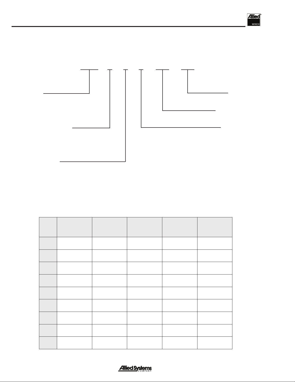
Unit Identification ...............................................1-2
Serial Number Codes.........................................1-3
Nameplate .........................................................1-3
Specifications ...........................................................1-4
Drum Wire Rope Capacities...............................1-4
Hydraulic Specifications.....................................1-4
Oil Specifications ...............................................1-4
Oil Capacity........................................................1-4
Maintenance Decal ............................................1-5
Torque Specifications.........................................1-5
Gear Train ................................................................1-6
Operation and Control ..............................................1-7
Hydraulic System......................................................1-8
Motor................................................................. 1-9
Brake................................................................1-10
Planetary Reducer ...........................................1-11
Counterbalance Relief Manifold .......................1-12
Control Manifold ...............................................1-13
Sequence of Operation...........................................1-14
Option Code B
BRAKE-ON ......................................................1-14
LINE-IN ............................................................1-16
LINE-OUT ........................................................1-18
BRAKE-OFF ....................................................1-20
Option Code D
BRAKE-ON ......................................................1-22
LINE-IN ............................................................1-24
LINE-IN Hi-Speed ............................................1-26
LINE-OUT ........................................................1-28
BRAKE-OFF ....................................................1-30
Komatsu D155AX-6/7 (K64)
BRAKE-ON ......................................................1-32
LINE-IN ............................................................1-34
LINE-OUT ........................................................1-36
BRAKE-OFF ....................................................1-38
Schematics.............................................................1-41
Troubleshooting......................................................2-1
General.....................................................................2-1
Mechanical/Hydraulic Troubleshooting Charts..........2-1
Service.....................................................................3-1
General ....................................................................3-1
Maintenance.............................................................3-1
Maintenance Points............................................3-1
Maintenance Schedule ......................................3-1
Hydraulic System Pressure Tests Ports .............3-2
Checks Before Operation...................................3-3
Checks During Operation...................................3-3
Hydraulic System Pressure Checks .........................3-3
Preparation.........................................................3-3
Pilot Supply Pressure Check..............................3-4
Motor Supply Pressure Check ...........................3-5
Brake Pressure Check .......................................3-6
BRAKE-OFF Pressure Check............................3-7
Brake Valve Pressure Check & Adjustment .......3-8
LINE-IN Pressure Check....................................3-9
LINE-OUT Pressure Check..............................3-10
PCOR Pressure Check ....................................3-11
Repairs ...................................................................4-1
General ....................................................................4-1
Winch Removal ........................................................4-1
Winch Disassembly ..................................................4-1
Intermediate Shaft Removal...............................4-2
Drum Shaft & Drum Removal.............................4-4
Hydraulic System Disassembly..........................4-8
Motor Shaft Removal & Disassembly...............4-10
BRAKE-OFF Clutch Disassembly....................4-14
Brake Disassembly ..........................................4-16
Planetary Reducer Disassembly......................4-18
Winch Assembly .....................................................4-20
Visual Inspection..............................................4-20
Brake Assembly ...............................................4-22
BRAKE-OFF Clutch Assembly.........................4-24
Motor Shaft Assembly & Installation ................4-28
Planetary Reducer Assembly...........................4-31
Hydraulic System Assembly.............................4-34
Drum & Drum Shaft Installation .......................4-36
Intermediate Shaft Installation .........................4-42
Contents

vi
Notes

Section 1
1 - 1
General
Introduction
This service manual is for the H12E hydraulic winch. The
following information is included in this manual:
Section 1. General includes operation descriptions
of systems and components as an aid for
troubleshooting and repair.
Section 2. Troubleshooting lists common problems
and the possible causes and corrections.
Section 3. Maintenance provides a guide for
periodic maintenance, checks and adjustments.
Section 4. Repairs describes the removal,
disassembly and assembly of the winch.
Description
The H12E Winch is a Power Forward (LINE-IN) and Power
Reverse (LINE-OUT) winch. The winch is powered by an
internal hydraulic motor connected to the tractor hydraulic
system. Oil flow and pressure are converted to rotational
energy by the winch motor. Motor torque is transmitted
through a holding brake, a planetary speed reducer and
two gear reductions to the drum. Hydraulic oil is supplied
by the tractor mounted pump. The tractor provides
hydraulic power, filtration and cooling. Operation of the
winch is controlled by a control lever and a BRAKE-OFF
switch located at the tractor’s control station.
The H12E winch BRAKE-OFF function permits the
wire rope to be pulled from the drum under increased
resistance.
The H12E winch has a maximum rated line pull capacity
of 150,000 lbs. (68,000 kg) when there is one layer of wire
rope on the drum. When there is more than one layer of
wire rope on the drum, the line pull is reduced.
Figure 1-1 H12E Winch
1
3
4
2
1
55
6
10
8
9
6
10
11
7
NAMEPLATE
2
NAMEPLATE
22
12
12
1. Drum
2. Access Cover for Motor and Hydraulics
3. Plug to Drain Oil
4. Plug to Check Oil Level
5. Tie Bar
6. Fill Plug
7. Bearing Retainer for Intermediate Shaft
8. Drum Shaft
9. Drawbar
10. Breather
11. Maintenance & Warning Decals
12. Serial Number Stamp

General
1 - 2
Unit Identification
Allied Winch S/N Nameplate Data For Tractor Mountings
Figure 1-2 Tractor Identification Codes and Available Gear Ratios for H12E Winch
Tractor Make Model and Starting Tractor Serial Number Where Applicable
H12E H 1 B 1001 K65
Sequence Number
Winch Model
Gear Ratio (Code #)
1 = 209:1
2 = 262:1
Hydraulic Operation Type
H = High Performance
Direction Control in Winch
T = Standard
Tractor Controls & Pump
Vehicle Code
See Figure 1-2
Internal Options
B = External Pump, PFR & BRAKE-OFF Clutch
D = External Pump, PFR, BRAKE-OFF Clutch
and Hi-Speed Control
1. In Addition to the serial number plate, the
serial number is stamped on the top left-
hand side of the frame. (See Figure 1-1
on page 1-1.)
2. Circled numbers in Figure 1-2 indicate
possible gear ratio.
Notes:
C
O
D
E
C
Caterpillar
E
John Deere
K
Komatsu
L
Liebherr
U
Shantui
50 D85-15
54 PR754
56 PR756
561 RL56
59 D8R Series II
64 D155AX-6/-7
SD32DQ
65 D275AX-5
74 D8T Tier 4
75 1050K
H12E = Standard
KH12E = Special

Section 1
1 - 3
Serial Number Codes
The serial number codes are described on page 1-2 of
this manual. The nameplate with the serial number code
is found on the top left hand side of the winch case. The
serial number code is also stamped on the left hand side
of the winch frame.
Nameplate
The rated capacity for the winch, as it is equipped, is
shown on the nameplate. Each winch is shipped from the
factory with a nameplate as shown in Figure 1-3. If the
nameplate is missing, or the wire rope does not match the
information on the nameplate, do not operate the winch
until its capacity is known and a new nameplate is installed.
Each winch must be operated within its rated capacity as
shown on the nameplate. Figure 1-3 Nameplate
ALLIED SYSTEMS COMPANY
21433 SW OREGON STREET
SHERWOOD, OREGON 97140 USA
WWW.ALLIEDSYSTEMS.COM
MODEL:
SERIAL NO.:
MAXIMUM LINE PULL*
BARE DRUM:
MAXIMUM WIRE
ROPE DIAMETER:
*LIMITED BY WIRE BREAKING STRENGTH. MAY BE LOWER DUE
TO AVAILABLE POWER FROM WINCH CARRIER. CONTINUOUS
LINE PULLS SHOULD BE LESS THAN WINCH CARRIER GVW.
MADE IN USA 2315005 REV A

General
1 - 4
Specifications
Drum Wire Rope Capacities (Drum: 14 Inch Diameter)
WIRE ROPE DIAMETER Length
(2/3 Drum Capacity )
Length
(Full Drum Capacity )
25 mm (1 in) 57 m (188 ft.) 87 m (286 ft.)
28 mm (1 1/8 in) 46 m (150 ft.) 70 m (229 ft.)
32 mm (1 1/4 in) 36 m (119 ft.) 55 m (182 ft.)
Notes: * Recommended length to fill drum up to 2/3 capacity to leave room for uneven spooling.
** Length to fill drum to full capacity. Will have no room for uneven spooling. Not recommended.
1. Wire Rope: IWRC 6 X 19, extra improved plow steel, with ferrule, tail chain and hook.
2. Loosely or unevenly spooled wire rope will change capacities. Use flexible wire rope with
independent wire rope center.
3. Ferrule: Junior (2-3/8” Long X 2-1/4” Diameter)
Figure 1-4 Drum Wire Rope Capacities
Hydraulic Specifications
Motor .......................... Bent axis variable displacement
Brake ............................... Dry multi-disc spring applied
Oil Specifications
The hydraulic winch motor and control system operate off of the tractor implement hydraulic system. The winch gear
case is filled with hydraulic transmission oil and is separate from the tractor hydraulic system. Factory fill for the gear
case is oil meeting Caterpillar TO-4 specification SAE 30 weight. For proper operation of the BRAKE-OFF clutch,
only oils meeting this specification should be used in the winch gear case.
Other hydraulic oils meeting this specification are:
ExxonMobil, Mobiltrans HD-30
Chevron, Chevron Drive Train Fluid HD SAE 30.
Oil Capacity
The oil capacity for H12E winch is approximately 7 gallons (26.5 liters).

Section 1
1 - 5
Figure 1-5 Maintenance Decal
Torque Specifications
Figure 1-6 Torque Specifications
Maintenance Decal
ITEM
TORQUE VALUES (Lubed)
ft-lbs. N-m kg-m
Control
Manifold
Solenoid Cartridge 12-15 16-20 5-6
Solenoid Cartridge Retaining Nut 1-2 1.4-2.7 0.45-0.9
Control Manifold to Bracket 28 38 12.7
Planetary Reducer to Clutch Housing 33 44 14.9
Brake
Assembly
Primary Disc to Spring Plate 15-18 20.3-24.4 6.8-8.16
Cover Plate 55-60 74.6-81.4 24.94-27.2
Brake-Off Clutch Assembly (Clutch Plate) 35-40 48-54 15.8-18.1
Clutch Housing to Planetary Reducer 33 44 14.9
Keeper 80 108 11
Drum Adapter to Drum
Bearing Retainer Plate 180 244 25
Motor to Brake
Brake Manifold Bracket 280 379 38
Bearing Cover
Clutch Housing
Planetary Reducer to Frame
Cover Top, Clamp Gasket
Frame to Top Guard
Top Guard to Tractor Mount
66 90 9
Bearing Retainer
Drum Shaft
Intermediate Shaft Cover
RH Cover Plate
165 225 23
Shaft Nut 400 550 181.4
Mounting Bracket (From Winch Side) 1105 1500 153
Mounting Bracket (From Tractor Side) 1900 2620 267

General
1 - 6
Gear Train (See Fig. 1-8)
A tractor mounted pump provides hydraulic flow to drive
the winch motor. The flow is controlled in the winch by
the hydraulic counterbalance relief manifold and a control
manifold. The motor is mounted to a multi-disc, spring
applied holding brake.The brake is applied when the motor
comes to a complete stop and is used to prevent drum
rotation due to internal hydraulic leakage to the motor.
A planetary gear assembly provides a 18.8:1 gear
reduction between the hydraulic motor and the planetary
output gear. The planetary output gear rotates at the same
direction as the hydraulic motor.
An intermediate gear shaft assembly gives further gear
reduction to increase torque at the winch drum.
Figure 1-8 Rotation Torque Transfer
Figure 1-7 Gear Train
DRUM GEAR
INTERMEDIATE GEAR
DRUM PINION GEAR
BRAKE-OFF CLUTCH
PLANETARY REDUCER
HOLDING BRAKE
HYDRAULIC MOTOR
D
U
C
E
R
H
YDRAULI
C
TUO-ENILNI-ENILNO-EKARB
Oil Supply
Oil Return
Oil Supply
Oil Return

Section 1
1 - 7
Operation & Control
There are two types of internal operation option codes:
Internal Operation Option Code B and Code D (see
Figures 1-9 and 1-10).
To operate the winch, the tractor must be running, and
the tractor work equipment lever must be in the unlocked
position. LINE-IN, LINE-OUT, and BRAKE-ON are
controlled by a proportional control lever.When the control
lever is in the BRAKE-ON or centered position, the holding
brake is automatically applied. Pushing the lever away
from the operator releases the brake and reels wire rope
off the drum (LINE-OUT). Pulling the lever towards the
operator releases the brake and reels wire rope onto the
drum (LINE-IN). Releasing the lever causes it to return to
the BRAKE-ON position, which stops the drum rotation
and applies the holding brake. Moving the lever a small
amount results in slow wire rope movement for inching
control. Line speed increases proportionally as the lever
is moved farther.
BRAKE-OFF is controlled by a switch located on the
operator console and directs hydraulic pressure to release
the brake-off clutch.
BRAKE-OFF is used when there is a load attached to the
winch wire rope and the operator wants to move the tractor
away from the load with wire rope spooling off the drum in
a controlled manner.
In BRAKE-OFF, hydraulic pressure is applied to release
the brake-off clutch. As wire rope is pulled from the winch,
the turning drum back-drives the winch gear train to the
brake-off clutch. The winch motor, brake, and planetary
reducer remain stationary. Mechanical drag through the
gear train and viscous drag in the brake-off clutch keep the
wire rope from bird-nesting as it is spooled off the drum.
BRAKE-OFF should not be used to lower
a suspended load or a load that can slide
down a slope.
Winches with option Code D have a HI-SPEED switch to
override automatic motor displacement control.
Figure 1-9 Control Levers & Switch
(Option Code B)
Figure 1-10 Control Levers & Switch
(Option Code D)
• Internal Option Code B
Operation of the winch is controlled by a control lever,
and a BRAKE-OFF switch at the tractor’s control station.
• Internal Option Code D
Operation of the winch is controlled by a control lever, a
BRAKE-OFF switch and a HI-SPEED switch at the trac-
tor’s control station.

General
1 - 8
Hydraulic System
Figure 1-11 Major Components
CONTROL
MANIFOLD
CBR MANIFOLD
(COUNTERBALANCE RELIEF)
BRAKE-OFF
CLUTCH
BRAKE
HYDRAULIC
MOTOR
PLANETARY
REDUCER
HYDRAULIC
MOTOR
BRAKE
BRAKE-OFF
CLUTCH
CONTROL
MANIFOLD
CBR MANIFOLD
(COUNTERBALANCE
RELIEF)
PLANETARY
REDUCER
GEAR,
SPIDER CLUTCH

Section 1
1 - 9
Motor (See Fig. 1-12)
The hydraulic motor is a bent axis variable displacement
motor. The default position of the motor is maximum
displacement. Control pressure operates a servo that
proportionally reduces motor displacement. At higher
motor pressure, a pressure compensator override (PCOR)
valve will shift the motor back to maximum displacement.
Figure 1-12 Hydraulic Motors
PCOR
The Pressure Compensator OverRide (PCOR) allows
the motor to shift between maximum and minimum
displacement depending on pressure. If the PCOR
pressure is set incorrectly, the winch may not be able
to shift to maximum displacement, causing a stall in the
motor. If the PCOR is set higher than the system pressure
of the machine hydraulics, the PCOR will never be allowed
to shift causing the winch to be stuck in high speed. See
Section 3 for testing procedures to evaluate if the PCOR
is set correctly for your application.
51V Series Motor
Last used on SN H12E***1085***
H1B Series Motor
First used on SN H12E***1086***
Case Drain
Minimum Displacement Adjustment
Pressure Compensator Override (PCOR) Valve
X1 Pressure Port
Motor A Port
Motor B Port
M5 Port
Motor
A Port
Motor
B Port

General
1 - 10
Figure 1-13 Brake
Brake (See Fig. 1-13)
The brake is a dry multi-disc spring applied design. The
springs push against a piston that applies force to the
friction discs and separator plates.The brake valve directs
pressurized oil to the piston and pushes back on the brake
springs to release the brake. The separator plates have
teeth that engage the splines inside the brake housing and
are held stationary. Teeth in the friction discs engage the
splines on the motor shaft and rotate with the shaft.
1. Retaining Ring
2. Retaining Ring
3. Bearing
4. Oil Seal
5. Cover Plate
6. Spline Shaft Assembly
7. Socket Head Shoulder Bolts
8. Primary Disc
9. Rotor Disc
10. Stator Disc
11. Case Gasket
12. Capscrew
13. Dowel Pin
14. Spring Plate
15. Springs
16. Piston
17. Back-Up Ring
18. O-Ring
19. Back-Up Ring
20. O-Ring
21. Bearing
22. Pressure Plate
23. Socket Head Screw

Section 1
1 - 11
Figure 1-14 Planetary Reducer
Planetary Reducer (See Fig. 1-14)
A two-stage planetary reducer is the first gear reduction
between the brake and the gear side of the winch. Oil in
this housing is common to the gear side of the winch.
Output shaft rotation is the same as input shaft rotation
at a reduced speed.
1. Sun Gear
2. Primary Carrier Assembly
3. Secondary Carrier Assembly
4. Ring Gear
5. Cover
6. Thrust Washer
7. Fitting
8. Fitting
9. Fitting
10. Label
4
3
2
1
8
5
9
7
6
10

General
1 - 12
Counterbalance Relief Manifold (See Fig. 1-15)
The counterbalance relief (CBR) manifold houses the
counterbalance valve and the high pressure relief valves.
The counterbalance valve is a load holding valve that
blocks return oil flow from the motor in the event supply
pressure drops below a set point in LINE-OUT mode.The
counterbalance valve allows oil to free flow in the LINE-
IN mode through a check valve. The high pressure relief
valves act as an overload relief when supply pressure
exceeds the setting of the valve.
Figure 1-15 Counterbalance Relief Manifold
Port A1
Port B
Relief Valve
Port A
Port B
Relief Valve
Counterbalance Valve
Port ACCUM B
Port TS
Port A1
Port B
Port ACCUM A
Table of contents
Other Allied Winch manuals