Allied H6G User manual

CUSTOMER
EDITION
P/N 599026W-H6GH1JE47 Printed in USA 10/28/2011
Please check the Allied Systems website
regularly for updates to this manual.
www.alliedsystems.com

Safety Precautions
Read, understand and observe the precautions on the following pages
to prevent injury to personnel and damage to equipment.
Winch serial number _________________________
Date put into service _________________________
NOTE: This publication may be translated to different languages for sole purpose
of easy reference in non-English speaking locations.
Should there be differences in interpretations to the text,
please refer to the English language edition published by Allied Systems Company
as the controlling document.

i
Safety Summary
Safety Summary
General Safety Notices
The following pages contain general safety warnings
which supplement specific warnings and cautions appear-
ing elsewhere in this manual. All electrical and hydraulic
equipment is dangerous. You must thoroughly review
and understand the Safety Summary before attempting
to operate, troubleshoot or service this winch.
The following symbols and terms are used to emphasize
safety precautions and notices in this manual:
DANGER
The “DANGER” symbol indicates a hazardous
situation which, if not avoided, will result in seri-
ous injury or death. Carefully read the message
that follows to prevent serious injury or death.
The “WARNING” symbol appears wherever
incorrect operating procedures or practices
could cause serious injury or death. Carefully
read the message that follows to prevent seri-
ous injury or death.
The “CAUTION” symbol appears where a
hazardous situation which, if not avoided,
could result in minor to moderate injury and
equipment damage.
This signal word alerts to a situation that is
not related to personal injury but may cause
equipment damage.
NOTE: …
The term “NOTE” highlights operating proce-
dures or practices that may improve equip-
ment reliability and/or personnel performance.
NOTE: All possible safety hazards cannot be
foreseen so as to be included in this manual.
Therefore, you must always be alert to poten-
tial hazards that could endanger personnel
and/or damage the equipment.
Safety Regulations
Each country has its own safety legislation. It is in the
operator’s own interest to be conversant with these regu-
lations and to comply with them in full. This also applies
to local bylaws and regulations in force on a particular
worksite.
Should the recommendations in this manual deviate from
those in the user’ country, the national regulations should
be followed.
Operation, Inspection, and Maintenance Warnings
Obey the following cautions and warnings
before using your winch to avoid equipment
damage, personal injury or death.
• Do not operate the winch unless your are authorized
and trained to do so.
• Do not operate the winch unless the vehicle is
equipped with a screen to protect the operator if
the wire rope breaks.
• Read, understand, and follow the operating, inspec-
tion, and maintenance instructions in this manual.
• Do not use the control levers for hand holds when
entering or leaving the vehicle.
• Do not permit other people near the control area
when you inspect or repair a machine.
• Never inspect, repair, or perform maintenance on
a machine that is in motion.
• Inspect the winch before each use:
»Make sure that the controls and instruments
operate correctly.
»Report the need for repairs immediately.
»Do not work with a damaged or worn wire rope.
»Do not use a winch that needs repairs.

ii
»If the wire rope and ferrule must be removed
from the drum, make sure the end of the wire
rope and ferrule are controlled when the ferrule
is released. The end of the wire rope can sud-
denly move from the drum like a compressed
spring when the ferrule is released, and cause
an injury.
• Stay in the operator’s seat when operating the
winch.
• Do not stand on the vehicle when operating the
winch.
• Avoid winch operation near people or other ma-
chines.
• Never stand nor permit others to stand in the bight
(loop) of a wire rope.
• Do not stand nor permit others to be near the winch
or wire rope when there is tension on the wire rope.
• Observe jobsite rules.
• Be in complete control at all times.
• Do not use the control levers as hangers for clothes,
water bags, grease guns, lunch pails, etc.
• Do not leave the vehicle when the winch wire rope
is under tension.
• Do not permit riders on the vehicle or load.
• Do not use the winch as an anchor for a double or
two-part line.
• Do not pull the hook through the throat or over the
drum, which will cause damage.
• When the winch is not in use, make sure the control
lever is in BRAKE-ON position and the winch brake
is applied.
• Do not use winch as a hoist. Tractor and skidder
mounted winches are designed for towing.
• Always inspect wire rope, tail chain and other rigging
components for wear, damage, broken strands or
abuse before use.
• Never use wire rope, tail chain or other rigging that
is worn-out, damaged or abused.
• Never overload wire rope, tail chain or rigging.
• Wire rope and tail chain will fail if worn-out, over-
loaded, misused, damaged, improperly maintained
or abused. Wire rope or tail chain failure may cause
serious injury or death!
• Do not terminate wire rope to tail chain by the use
of a knot.
• Do not handle wire rope if the hook end is not free.
A load could break away, suddenly tensioning the
wire rope, resulting in serious injury or death.
• Stay clear of wire rope entry areas (fairlead or arch
rollers, winch drum etc).
KG
KG
KG
KG

iii
Safety Summary
• Make sure ground personnel are in plain view of the
operator, and at a distance of at least 1½ times the
working length of the wire rope.
• Make sure that any hand signals used by ground
personnel are clearly defined and understood by
everyone involved.
• Do not attempt to “jerk” or “shock” a load free. Doing
so can cause loads in excess of the rated capacity
of the wire rope, winch, or mounting hardware.
• Replace any parts only with genuine Allied
Winch parts. Refer to Parts Manual 599027W-
H6GH1JE47.
• Maintain a minimum of three (3) complete wraps
of wire rope on the drum for normal operation. It
may help to paint the last five wraps of wire rope
a contrasting color, to serve as a visual indicator.
• Do not handle wire rope with bare hands. Wear
leather gloves at all times.
• Align the tractor with the load to prevent side load-
ing the winch, and to maintain even spooling of the
wire rope.
• If applying tension to the wire rope manually during
spooling:
»ensure that the operator is winching in slowly,
»keep your hands and clothing well clear of any
rollers or the winch drum,
»do not maintain tension by letting the wire rope
to slip through your hands,
»use a hand-over-hand technique to maintain
tension.
• Be aware of the ground conditions, and make sure
the ground and tractor are stable enough to pull
the intended load.
• Do not attempt to pull loads in excess of the rated
capacity of the winch.
• Keep yourself informed of any applicable codes,
regulations and standards for the job.
• Your winch may have temperature shut-off system
for protection of tractor and winch. Manual override
of high temperature shut-off will cause damage to
tractor and winch.
• This winch is neither intended, designed, nor rated
for any application involved in the lifting or moving
of personnel.
• Use only the lubricants listed in the Recommended
Oil List. See pages 1-4 and 1-5.
• Do not weld on any part of the winch. Contact Allied
Systems if weld repairs are needed.
• The hydraulic system must be kept clean and free
of contamination at all times.
• Be aware of the hazards of pressurized hydraulics:
»Wear personal protective equipment, such as
gloves and safety glasses, whenever servicing
or checking a hydraulic system.
»Assume that all hydraulic hoses and compo-
nents are pressurized. Relieve all hydraulic
pressure before disconnecting any hydraulic
line.
»Never try to stop or check for a hydraulic leak
with any part of your body; use a piece of card-
board to check for hydraulic leaks.
»Small hydraulic hose leaks are extremely dan-
gerous, and can inject hydraulic oil under the
skin, even through gloves.
»Infection and gangrene are possible when
hydraulic oil penetrates the skin. See a doctor
immediately to prevent loss of limb or death.

iv
Notes

v
Contents
Safety Summary..........................................................i
General......................................................................... 1-1
Introduction........................................................................ 1-1
Description ........................................................................ 1-1
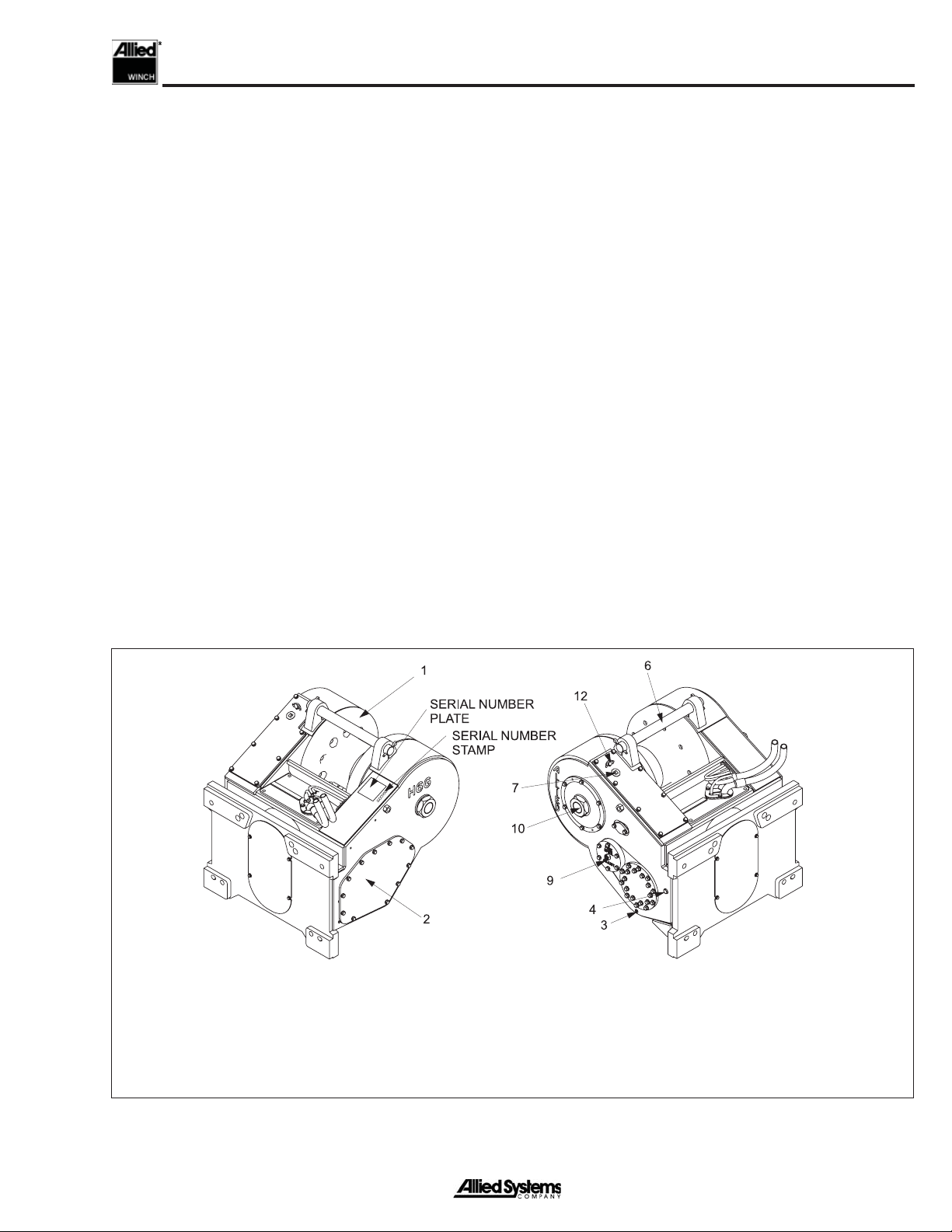
Unit Identification........................................................ 1-2
Serial Number Codes................................................. 1-3
Nameplate.................................................................. 1-3
Specifications .................................................................... 1-4
Drum Wire Rope Capacities....................................... 1-4
Hydraulic Specifications ............................................. 1-4
Oil Specifications........................................................ 1-4
Oil Capacity ................................................................ 1-4
Torque Specifications ................................................. 1-5
Gear Train ......................................................................... 1-6
FREESPOOL Operation............................................. 1-7
Operation and Control ....................................................... 1-8
Hydraulic System............................................................... 1-9
Planetary Reducer ..................................................... 1-9
Brake ........................................................................ 1-10
Motor ........................................................................ 1-11
Directional Control Manifold ..................................... 1-12
Logic Control Manifold.............................................. 1-12
HI-SPEED Limit Switch............................................ 1-12
Electronic Control Panel ........................................... 1-12
Sequence of Operation.................................................... 1-13
BRAKE-ON............................................................... 1-13
LINE-IN..................................................................... 1-14
HI-SPEED LINE-IN................................................... 1-16
LINE-OUT................................................................. 1-18
HI-SPEED LINE-OUT............................................... 1-20
FREESPOOL ........................................................... 1-22
Schematics...................................................................... 1-25
Troubleshooting ..................................................... 2-1
General.............................................................................. 2-1
Step-By-Step Pump & Controller Troubleshooting............. 2-2
Troubleshooting Analysis Check Chart.............................. 2-4
Service ......................................................................... 3-1
General ............................................................................. 3-1
Maintenance...................................................................... 3-1
Maintenance Points.................................................... 3-1
Maintenance Schedule............................................... 3-1
Checks Before Operation ........................................... 3-2
Checks During Operation........................................... 3-2
FREESPOOL Drag Adjustment......................................... 3-2
Hydraulic System Pressure Checks .................................. 3-2
Preparation................................................................. 3-2
Pressure Gauges ....................................................... 3-2
Standby Pilot Supply Pressure Check........................ 3-2
Maximum Pilot Supply Pressure Check ..................... 3-3
Counterbalance Valve Pressure Check...................... 3-3
Motor Supply Pressure Check.................................... 3-3
Brake Pressure Check................................................ 3-3
Brake Valve Pressure Check ...................................... 3-3
FREESPOOL Pressure Check................................... 3-4
High Speed Pressure Check...................................... 3-4
LINE-IN Pressure Check............................................ 3-5
LINE-OUT Pressure Check ........................................ 3-5
Valve Setting Procedures .................................................. 3-5
Load Sense Relief Valve ............................................ 3-5
Pilot Supply Reducing Valve ...................................... 3-5
Hydraulic System Pressure Tests Table............................. 3-6
Repairs ........................................................................ 4-1
General ............................................................................. 4-1
Winch Removal.................................................................. 4-1
Winch Disassembly ........................................................... 4-1
Intermediate & FREESPOOOL Shaft Removal.......... 4-2
Drum Shaft & Drum Removal..................................... 4-5
Hydraulic System Disassembly.................................. 4-9
Motor Shaft Removal & Disassembly ....................... 4-14
Motor Disassembly................................................... 4-17
Brake Disassembly................................................... 4-20
Planetary Reducer Disassembly .............................. 4-22
Winch Assembly .............................................................. 4-24
Visual Inspection ...................................................... 4-24
Planetary Reducer Assembly................................... 4-26
Brake Assembly ....................................................... 4-28
Motor Assembly........................................................ 4-30
Motor Shaft Assembly & Installation......................... 4-33
Hydraulic System Assembly..................................... 4-36
Drum & Drum Shaft Installation................................ 4-41
Intermediate & FREESPOOL Shaft Installation ....... 4-46
Winch Installation ............................................................ 4-50
Contents

vi
Notes

Section 1
1 - 1
General
Introduction
This service manual is for the H6G winch. The following
information is included in this manual:
Section 1. General includes operation descriptions
of systems and components as an aid for trouble-
shooting and repair.
Section 2. Troubleshooting lists common problems
and the possible causes and corrections.
Section 3. Maintenance provides a guide for peri-
odic maintenance, checks and adjustments.
Section 4. Repairs describes the removal, disas-
sembly, assembly, and installation of the winch.
Description
The H6G Winch is a Power Forward (LINE-IN) and Power
Reverse (LINE-OUT) winch. The winch is powered by
an internal hydraulic motor connected to the tractor hy-
draulic system. Oil flow and pressure are converted to
rotational energy by the winch motor. On the H6G, torque
is transmitted through a holding brake, a planetary speed
reducer and two gear reductions to the drum. Hydraulic
oil is supplied by the tractor mounted auxiliary pump cir-
cuit and utilizes oil, filtration and cooling provided by the
tractor circuit. Flow to the winch is controlled by a control
lever and electrical switches located at the tractor’s control
station.
The H6G winch has a FREESPOOL function.The FREE-
SPOOL function permits the wire rope to be pulled from
the drum.
The H6G winch has a maximum rated line pull capacity
of 266,880N (60,000 lb.) when there is one layer or less
of wire rope on the drum. When there is more than one
layer of wire rope on the drum, the maximum rated line
pull is reduced.
Figure 1-1 H6G Winch
1. Drum
2. Access Cover for Motor and Winch Hydraulics
3. Plug to Drain Oil
4. Plug to Check Oil Level
6. Tie Rod
7. Fill Plug
9. Bearing Retainer for Intermediate Shaft
& Freespool drag Adjuster
10. Right Side Drum Shaft
11. Drawbar (Not Shown)
12. Breather

General
1 - 2
Unit Identification
Allied Winch S/N Nameplate Data For Tractor Mountings
H6G H 1 J 1501 E47
John Deere 850JR Tractor
Sequence Number
Internal Options
Winch Model
Hydraulic Operation Type
Gear Ratio Code
1 = 60:1
H = High Performance
(Hydraulic or Hydrostatic with 2-Speed)
J = External Pump, PFR, FS
with CARC Green Paint & 50mm Dia Pin Special Drawbar;
without Tractor Side Installation Parts
In Addition to the serial number plate,
the serial number is stamped on the top
left-hand side of the frame. See Figure
1-1 on page 1-1.
Note:
H6G was previously known as WH6G.
The "W" designation has been dropped for simplicity.

Section 1
1 - 3
Serial Number Codes
The serial number codes are described on page 1-2 of
this manual. The nameplate with the serial number code
is found on the top left hand side of the winch case. The
serial number code is also stamped on the left hand side
of the winch frame. See Figure 1-1 on page 1-1.
Nameplate
The rated capacity for the winch, as it is equipped, is
shown on the nameplate. Each winch is shipped from the
factory with a nameplate as shown in Figure 1-2. If the
nameplate is missing, or the wire rope does not match the
information on the nameplate, do not operate the winch
until its capacity is known and a new nameplate is installed.
Each winch must be operated within its rated capacity as
shown on the nameplate.
If the winch is equipped with a log arch, the maximum wire
rope size is reduced. Refer to the nameplate for details.
Figure 1-2 Nameplate
2311482-b.pdf

General
1 - 4
Specifications
Drum Wire Rope Capacities (Drum: 10 Inch Dia)
Figure 1-5 Recommended Oil List
Figure 1-3 Drum Wire Rope Capacities
Oil Specifications
For inside winch housing, use the following oils:
Oil Capacity
The oil capacity for the H6G winch is 8.5 quarts (8
liters).
Hydraulic Specifications
Motor .............................. Dual displacement vane-type
Brake ............................... Dry multi-disc spring applied
Wire Rope Diameter H6G Capacity
29 mm (1 1/8 in.) 51 m (167 ft)
Note: Loosely or unevenly spooled line will change
capacities. Use flexible wire rope with independent
wire rope center.
Figure 1-4 Ferrule Size and Type for H6G
Ferrule Size & Type
H6G Light Ferrule 2 1/4” x 2.0” Dia.
Hydraulic System (Pump): Use Tractor Fluid
(Gear Oil MIL-PRF-2105E)
Winch Case (Gear Train):

Section 1
1 - 5
Figure 1-6 Torque Specifications
ITEM TORQUE VALUES
ft-lbs. N-m kg-m
Housing Covers (1/2 UNC Gr. 8) 80 108 11
Drum Shaft Assembly
Drum Adapter to Drum Capscrews (5/8 UNF Gr. 8)
Bearing Retainer Capscrews (1/2 UNF Gr. 8)
155
90
210
122
22
12
Motor Shaft Gear Retainer Capscrews (3/8 UNC Gr. 8)
3-Port Manifold to Motor Capscrews (7/16 UNC Gr. 8)
Directional Manifold Mounting Capscrews (3/8 UNC Gr. 8)
33
52
33
44
71
44
4
7
4
Torque Specifications

General
1 - 6
Gear Train (See Fig. 1-7 & 1-8)
The tractor pump drives the hydraulic motor with hydraulic
oil supply. Pressure in the hydraulic motor is load induced
through the winch gear train. The motor shaft rotates to
give LINE-IN or LINE-OUT with supply oil and return oil
is directed back to the tractor reservoir. The motor is at-
tached to a multi-disc spring applied brake that holds the
winch drum in a fixed position when no power operation
occurs. If oil is supplied to the hydraulic motor, the brake
is simultaneously released with pilot control pressure.
When oil is not supplied to the motor, a spring applies
the brake.
The hydraulic motor can operate at half displacement
when the operator selects the HI-SPEED switch. At half
displacement the gear train rotates at roughly twice the
speed.
A planetary gear assembly gives a 1:6 gear reduction
between the hydraulic motor and the planetary output
gear. Motor shaft direction of rotation is the same as the
planetary output gear at 1/6th the speed.
An intermediate gear assembly gives further gear re-
duction to increase torque at the winch drum. A dental
clutch with splines engages the drum pinion gear and the
intermediate gear. The operator can disengage the dental
clutch with an electric switch to engage the FREESPOOL
feature.
Figure 1-8 Rotation Torque Transfer
BRAKE-ON
Oil Supply
Oil ReturnOil Supply
Oil Return
LINE-IN LINE-OUT
Durm Gear
Intermediate Gear
with Freespool
Drum Pinion Gear
Planetary Reducer
Brake
Hydraulic Motor
A drum gear engages the drum pinion gear and is con-
nected to the drum. When power is applied to the gear
train, the drum will rotate in the forward or reverse direc-
tion. The drum adapter connects the drum to the drum
gear. The other side of the drum runs on roller bearings
held by the drum shaft. The drum shaft is connected to
the winch case.
Figure 1-7 Gear Train

Section 1
1 - 7
Figure 1-10 FREESPOOL Arrangement
1 Shifter
2 O-Ring
3 FREESPOOL Piston
4 O-Ring
5 Fitting
11 Washer
13 Gear
14 Capscrew
15 Piston, FREESPOOL Adjust
16 O-Ring
17 Bearing, Cup
18 Cover
19 Bearing. Cone
20 Shaft, Intermediate
21 Gear, Pinion
21 Gear, Pinion
22 Clutch
23 Setscrew
24 Nut
FREESPOOL Operation (See Fig. 1-9 & 1-10)
The FREESPOOL arrangement allows mechanical dis-
engagement of the drum gear from the remainder of the
gear train.When FREESPOOL is selected, a hydraulically-
actuated sleeve disengages the dental clutch from the
intermediate shaft. The drum is now disconnected from
the brake and the winch cannot support a load.
FREESPOOL should not be used if there is a
load on the wire rope. An uncontrolled release
of the load will occur. Loss of the load can
result in injury and/or equipment damage.
The yellow indicator panel on the selector switch lights
when the winch is in FREESPOOL.
NOTE: The dental clutch may not disengage if there
is a load on the wire rope. Figure 1-9 FREESPOOL Operation
INTERMEDIATE
GEAR
DENTAL CLUTCH
INTERMEDIATE
SHAFT
DRUM PINION
GEAR

General
1 - 8
Figure 1-11 Winch Controls
Operation & Control (See Fig. 1-11)
The H6G winch is designed to operate on a load sense, pilot
operated hydraulic system.When the tractor is running, the
winch is ready to operate but no oil is flowing to the winch.
Control (pilot) pressure is present at the winch.
The control lever and electrical switches are used to select
the following operations:
• BRAKE-ON (spring-centered position)
• LINE-IN
• LINE-OUT
• FREESPOOL
• HI-SPEED (either LINE-IN or LINE-OUT)
The tractor must be running and the auxiliary hydraulic
function switch, if equipped, must be on. LINE-IN, LINE-
OUT and BRAKE-ON are controlled by a proportional
control lever.
When the control lever is in the BRAKE-ON or centered
position, the holding brake is automatically applied. Push-
ing the lever away from the operator releases the brake
and reels wire rope off the drum (LINE-OUT). Pulling the
lever towards the operator releases the brake and reels
wire rope onto the drum (LINE-IN). Releasing the lever
causes it to return to the BRAKE-ON position, which stops
the drum rotation and applies the holding brake. Moving the
lever a small amount results in slow wire rope movement
for inching control. Line speed increases proportionally as
the lever is moved farther.
The switch panel contains two rocker switches to control
FREESPOOL and HI-SPEED.The tractor must be running
to supply hydraulic power to operate these functions. A light
shows when a switch is on.
The FREESPOOL switch incorporates a lock to prevent
inadvertent actuation. The slide lock must be released
before the switch can be turned on.
Before operating the winch in LINE-IN or LINE-
OUT mode, ensure the FREESPOOL light is
not illuminated. Doing so may result in loss of
load.
The HI-SPEED switch is a dual-action momentary switch.
Pushing it towards the operator allows the winch to oper-
ate at low speed, while pushing the switch away from the
operator activates HI-SPEED. When in HI-SPEED mode,
the winch will automatically shift to low speed when the
load exceeds a certain percentage of the rated load. For
heavy loads or when better control is desired, the winch
should be operated in low speed. For light loads and faster
wire rope speed, operate the winch in HI-SPEED mode.
The green light in the speed selector switch indicates HI-
SPEED operation.
LINE-OUT DECAL
CONTROL LEVER
LINE-IN DECAL
FREESPOOL SWITCH
(YELLOW)
DECAL
HI-SPEED SWITCH
(GREEN)

Section 1
1 - 9
Hydraulic System
Planetary Reducer (See Fig. 1-12)
The planetary speed reducer is the first gear reduction
between the brake and the gear side of the winch. Oil in
Figure 1-12 Planetary Reducer
10 11
13
14
12
15
16
18
17 19
6
7
8
9
4
35
1
1. Output Shaft
3. Bearing Cone
4. Bearing Cup
5. Plug
6. Hub
7. Bearing Cup
8. Bearing Cone
9. Thrust Washer
10. Retaining Ring
11. Ring Gear
12. Carrier Assembly
13. Sun Gear
14. Thrust Washer
15. Cover
16. Plug
17. Washer
18. Capscrew
19. Plug
this housing is common to the gear side of the winch and
output shaft rotation is the same as input shaft rotation
at 1/6th the speed.

General
1 - 10
Figure 1-13 Brake
Brake (See Fig. 1-13)
The brake is a dry multi-disc spring applied design. The
springs push against a piston that applies force to the
friction discs and separator plates.The brake valve directs
pressurized oil to the piston and pushes back on the brake
1. Retaining Ring
2. Retaining Ring
3. Bearing
4. Oil Seal
5. Cover Plate
6. Spline Shaft Assembly
7. Socket Head Shoulder Bolts
8. Primary Disc
9. Rotor Disc
10. Stator Disc
11. Case Gasket
12. Capscrew
13. Dowel Pin
14. Spring Plate
15. Springs
16. Piston
17. Back-Up Ring
18. O-Ring
19. Back-Up Ring
20. O-Ring
21. Bearing
22. Presure Plate
23. Socket Head Screw
springs to release the brake. The separator plates have
teeth that engage the splines inside the brake housing and
are held stationary. Teeth in the friction discs engage the
splines on the motor shaft and rotate with the hub.

Section 1
1 - 11
Motor (See Fig. 1-14)
The hydraulic motor is a dual displacement vane-type
motor for high-performance winches. Full or half displace-
ment is selected at the motor by shifting an integral two
position spool. The default position is full displacement
Figure 1-14 Motor
when pressure is not signaled by the winch to the spool.
Output speed is proportional to input flow from the pump
and inversely proportional to the motor displacement.
1. Seal Plate Snap Ring
2. Seal Plate
3. Seal Shaft
4. Steel Plate
5. Seal Plate O-Ring
6. Bearing Snap Ring
7. Ball Bearing
8. Shaft
9. Bolt
10. Front Housing, Internal
11. Dowel Pins, Front
12. O-Ring
13. Ball Checks
14. Screw
15. Two-Speed Plate
16. Stator
17. Rotor
18. Rotor Vane
19. Rotor Vane Spring, Outer
20. Rotor Vane Spring, Inner
21. Stator Vane
22. Stator Vane Spring
23. Dowel Pins, Rear
24. Needle Bearing
25. Rear Housing

General
1 - 12
Directional Control Manifold
The directional control manifold controls the direction
of hydraulic flow to the winch motor. When the operator
moves the control lever into the LINE-IN or LINE-OUT
position, a pressure response is signaled to one side of
the directional control valve, and oil flow is delivered to
the motor. The directional control manifold also houses
several other winch control features including the coun-
terbalance valve, load sense relief valve, and load sense
check valves. The counterbalance valve is a load holding
valve that blocks return oil flow from the motor in the event
supply pressure drops below a set point in LINE-OUT
mode. This valve also acts as an overload relief valve
when supply pressure exceeds the setting of the valve.The
counterbalance valve allows oil to free flow in the LINE-IN
mode through a check valve. The load-sense relief valve
limits the winch load signal to the tractor pump to limit the
winch hydraulic system pressure. The load sense check
valves are used to communicate winch motor pressure
to the pump load sense controller. See Figure 1-22 for
schematics on page 25.
Logic Control Manifold
The logic control manifold is used to communicate pres-
sure signals that control the BRAKE-ON, HI-SPEED, and
FREESPOOL. The manifold contains a series of shuttle
valves, a directional valve, and three solenoid valves. One
shuttle is used to send a pressure response to the brake
when the winch is shifted to LINE-IN or LINE-OUT. The
two other shuttle valves allow communication between
HI-SPEED and FREESPOOL functions. The brake valve
provides pressure to the brake when the LINE-IN or LINE-
OUT control pressure exceeds the pilot setting of the
valve.The HI-SPEED and FREESPOOL valves are 3-way
electric over hydraulic valves that communicate pressure
responses to respective functions when activated.
HI-SPEED Limit Switch
The HI-SPEED limit mechanism is comprised of a pres-
sure switch and electric relay. When the HI-SPEED func-
tion is activated, the solenoid valve in the logic control
manifold directs oil to the motor speed spool in the motor.
If the system pressure exceeds a certain percentage of the
rated load, the pressure switch sends a signal to the relay,
which then opens and deactivates HI-SPEED. The motor
speed will not reactivate until you re-initialize the switch.
Electronic Control Panel
Depending on the options on the winch, the electronic
control panel contains two electric rocker switches to
operate HI-SPEED and FREESPOOL functions. Each
switch is equipped with integral LED indicator to show if the
function is active. The FREESPOOL switch incorporates
a lock to prevent the switch from being accidentally turned
on. To operate, slide the locking tab first, then push the
rocker switch. The HI-SPEED switch is a three position
switch on momentary rocker. High speed is deactivated
by pulling a load that generates pressure beyond the set-
ting of the HI-SPEED limit switch or manually by rocking
the switch back.
Table of contents
Other Allied Winch manuals
Popular Winch manuals by other brands

Huchez
Huchez PALANBOX 80 instruction manual

KStrong
KStrong AFA930301 User instruction manual

Paccar Winch
Paccar Winch Braden BA2A Installation maintenance and service manual

Warn
Warn Tabor 10000 quick start guide

Monzana
Monzana DBSW003 instructions

Cycle Country
Cycle Country 25-9012 Assembly & owners manual

Comeup
Comeup CWS-80 instruction manual

Warrior Winches
Warrior Winches 9500HS Assembly & operating instructions

Runva
Runva 20000NH Assembly & operating instructions

Kellfri
Kellfri 21-KW1000 operating instructions

Champion Power Equipment
Champion Power Equipment 13050 Owner's manual & operating instructions

Champion Power Equipment
Champion Power Equipment T-P2500 Assembly & operating instructions