Allis-Chalmers LA-600 User manual

INDEX
TO
INSTRUCTION
BOOK
rr
r
‘
“
am
•
if
4
Tiiki
<
mimo
>
wT
>
r
‘
“
mir
‘
i
“
t
Tufiii
urTinrni
^
BviV
SECTION
I
INSTALLATION
AND
INSPECTION
A
.
INTRODUCTION
B
.
WARRANTY
C
.
RECEIVING
AND
INSPECTION
FOR
DAMAGE
D
.
CAUTIONS
TO
BE
OBSERVED
E
.
INSTALLATION
F
.
STORAGE
Go
MAINTENANCE
H
o
RENEWAL
PARTS
SECTION
II
OPERATION
A
,
DESCRIPTION
1
Manually
Operated
Breaker
Electrically
Operated
Breaker
o
2
,
RACKING
MECHANISM
,
DRAWOUT
INTERLOCK
AND
LIFTING
BAR
B
.
SECTION
III
(
V
A
.
MAINTENANCE
B
.
LUBRICATION
C
.
MAINTENANCE
CLOSING
D
CONTACT
REPLACEMENT
SECTION
IV
A
.
INTRODUCTION
1
.
SELECTION
OF
SETTINGS
2
,
RELEASE
MAGNET
3
Courtesy of NationalSwitchgear.com
f
ALUS
-
CHALMERS
LIST
OF
ILLUSTRATIONS
DESCRIPTION
FIGURE
NO
.
TYPICAL
LA
-
600
BREAKER
OUTLINE
TYPICAL
OPERATING
MECHANISM
(
MANUALLY
OPERATED
BREAKER
)
TYPICAL
OPERATING
MECHANISM
(
ELECTRICALLY
OPERATED
BREAKER
)
TYPICAL
WIRING
DIAGRAM
FOR
ELECTRICALLY
OPERATED
BREAKERS
TYPICAL
RACKING
MECHANISM
S
-
DRAWOUT
INTERLOCK
MAINTENANCE
CLOSING
TYPICAL
PANEL
ASSEMBLY
TYPICAL
STATIC
OVERCURRENT
TRIP
DEVICES
TYPICAL
BREAKER
RATING
PLATE
AND
CURRENT
TRANSFORMERS
SHAFT
LOCKS
AND
CALIBRATION
MARKS
FOR
STATIC
TRIP
DEVICES
PORTABLE
TEST
SET
FOR
STATIC
TRIP
DEVICES
TYPICAL
TRIP
CURVES
(
SELECTIVE
STATIC
TRIP
)
TYPICAL
TRIP
CURVES
(
DUAL
STATIC
TRIP
)
CONNECTIONS
FOR
FUNCTION
TEST
TYPICAL
RELEASE
MAGNET
TYPICAL
SECONDARY
DISCONNECTS
TYPICAL
AUXILIARY
SWITCH
TYPICAL
SHUNT
TRIP
TYPICAL
UNDERVOLTAGE
DEVICE
TYPICAL
BELL
ALARM
(
MANUAL
RESET
)
TYPICAL
BELL
ALARM
(
ELECTRICAL
RESET
)
1
2
2
A
«
3
4
5
6
7
7
A
7
B
7
C
7
D
7
E
7
F
8
11
12
13
14
15
ISA
V
>
.
TABLES
TABLE
NO
.
OPERATING
PROCEDURE
(
MANUALLY
OPERATED
BREAKER
)
OPERATING
PROCEDURE
(
ELECTRICALLY
OPERATED
BREAKER
)
1
.
2
*
3
.
MAINTENANCE
CLOSING
4
»
CURRENT
TRANSFORMERS
(
Fig
.
7
A
)
Courtesy of NationalSwitchgear.com

iHSIIWiONS
FOR
THE
INSTALLATION
AND
OPERATION
OF
ALUS
-
CHALHERS
TYPE
"
LA
"
LOW
VOLTAGE
AIR
CIRCUIT
BREAKERS
AND
AUXILIARY
EQUIPMENT
SECTION
I
.
INSTALLATION
AND
INSPECTION
A
.
INTRODUCTION
The
type
"
LA
”
air
circuit
breakers
may
be
furnished
for
mounting
In
any
one
of
three
ways
.
They
may
be
used
in
metal
enclosed
switch
-
gear
of
the
drawout
type
,
in
individual
enclosures
(
pullout
type
)
,
or
for
stationary
mounting
in
a
customer
'
s
own
enclosing
case
or
switchboard
,
"
LA
1
?
breakers
are
completely
assembled
,
tested
,
and
calibrated
at
the
factory
in
a
vertical
position
and
must
be
so
installed
to
operate
properly
.
Customer
'
s
primary
connections
should
be
adequately
braced
against
the
effects
of
short
circuit
currents
to
prevent
overstressing
the
breaker
terminals
,
WARRANTY
Allis
~
ChaImers
"
LA
"
air
circuit
breakers
are
warranted
to
be
free
of
defects
in material
and
workmanship
for
a
period
of
one
year
after
delivery
to
the
original
purchaser
.
This
warranty
Is
limited
to
the
furnishing
of
any
part
which
to
our
satisfaction
has
been
proven
defective
Chalmers
will
not
in
any
case
assume
responsibility
for
allied
equipment
of
any
kind
.
C
,
RECEIVING
AND
INSPECTION
FOR
DAMAGE
immediately
upon
receipt
of
this
equipment
,
carefully
remove
all
packing
traces
and
examine
parts
,
checking
them
against
the
packing
list
and
noting
any
damages
incurred
in
transit
.
If
such
is
disclosed
,
a
damage
claim
should
be
filed
at
once
with
the
.
transportation
company
and
A
!
Hs
-
Chalmers
notified
,
D
,
CAUTIONS
TO
BE
OBSERVED
IN
THE
INSTALLATION
AND
OPERATION
OF
"
LA
"
CIRCUIT
BREAKERS
1
,
Read
Instruction
Book
before
Installing
or
making
any
changes
or
adjustments
on
the
breaker
,
2
,
As
the
closing
springs
on
stored
-
energy
breakers
may
be
^
charged
in
either
the
breaker
open
or
closed
position
,
extreme
care
should
be
.
taken
to
discharge
the
springs
before
working
on
the
breaker
.
3
,
When
closing
manually
-
operated
breakers
,
always
grasp
-
'
dosing
handle
firmly
until
it
is
returned
to
the
normal
vertical
position
.
Check
current
ratings
and
serial
numbers
against
single
line
diagram
to
assure
that
breakers
are
properly
located
in
switchgear
at
insta
1
latf
on
.
A
11
4
,
Check
the
alignment
of
the
.
secondary
disconnect
fingers
to
ensure
against
misalignment
due
to
possible
distortion
of
fingers
during
shipment
and
handling
.
Once
the
breaker
Is
energised
,
it
should
not
be
touched
,
except
for
operating
,
since
most
of
the
component
parts
are
also
energized
.
5
»
6
,
Courtesy of NationalSwitchgear.com

E
.
INSTALLATION
The
"
LA
"
air
circuit
breaker
is
completely
adjusted
,
tested
,
and
Inspected
at
the
factory
before
shipment
,
but
careful
check
should
be
made
to
be
certain
that
shipment
or
storage
has
not
resulted
in
damage
or
change
of
adjustment
.
Circuit
breakers
should
be
Installed
in
a
clean
,
dry
,
wel
1
-
ventiiated
place
in
which
the
atmosphere
is
free
from
destructive
acid
or
alkali
fumes
.
Stationary
-
type
breakers
should
be
mounted
high
enough
to
prevent
injury
to
personnel
either
from
circuit
interruption
or
from
moving
parts
during
automatic
opening
of
the
breaker
.
Allot
*
/
sufficient
space
to
permit
access
for
cleaning
and
inspection
and
adequate
clearance
to
insulating
barrier
above
the
breaker
to
prevent
damage
from
arcing
during
Interruption
.
Before
installing
,
make
certain
that
the
breaker
contacts
are
in
the
open
position
.
1
,
After
the
breaker
Is
installed
in
position
,
close
it
manually
by
the
maintenance
closing
method
(
See
Section
III
)
to
check
proper
functioning
of
the
mechanism
and
contacts
.
(
CAUTION
:
MAKE
SURE
CIRCUIT
IS
NOT
ENERGIZED
)
.
During
the
closing
operation
,
observe
that
the
contacts
move
freely
without
interference
or
rubbing
between
movable
arcing
contacts
and
parts
of
the
arc
chutes
.
Then
refer
to
Section
II
of
the
Instruction
Book
for
a
detailed
description
of
the
circuit
breaker
operating
characteristics
before
putting
the
breaker
in
service
.
2
,
Trip
units
and
accessory
devices
should
receive
a
thorough
check
prior
to
placing
the
breaker
In
service
to
be
certain
that
adjustments
are
proper
and
parts
are
not
damaged
,
3
.
Cubicle
-
mounted
breakers
of
the
drawout
type
are
equipped
with
a
draw
-
out
interlock
to
prevent
movement
of
a
closed
breaker
into
or
out
of
the
connected
position
.
See
Section
II
of
the
Instruction
Book
for
a
description
of
the
interlock
.
Its
operation
should
be
checked
before
the
breake
*
'
is
energized
,
4
.
Upon
completion
of
the
installation
Inspection
,
the
breaker
is
ready
to
be
energized
after
the
control
wiring
,
if
any
,
Is
checked
and
the
Insulation
tested
.
JV
«
v
>
F
.
STORAGE
When
breakers
are
not
to
be
put
into
immediate
use
,
they
should
be
wrapped
or
covered
with
a
non
-
absorbant
material
to
provide
protection
from
plaster
,
concrete
dust
or
other
foreign
matter
.
Breakers
should
not
be
exposed
to
the
action
of
corrosive
gases
or
moisture
.
In
areas
of
high
humidity
or
temperature
fluctuations
,
space
heaters
or
the
equivalent
should
be
provided
.
G
.
MAINTENANCE
Occasional
checking
and
cleaning
of
the
breaker
will
promote
long
and
trouble
-
free
service
.
A
periodic
inspection
and
servicing
at
least
every
six
months
should
be
included
In
the
breaker
maintenance
routine
.
If
the
circuit
breaker
Is
not
operated
during
extended
periods
,
the
breaker
should
not
remain
in
either
the
closed
or
open
position
any
longer
than
six
months
,
Maintenance
opening
and
closing
operations
should
be
made
to
ensure
freedom
of
movement
of
all
parts
.
H
.
RENEWAL
PARTS
When
ordering
renewal
parts
,
specify
the
complete
name
-
plate
data
including
breaker
serial
number
.
Courtesy of NationalSwitchgear.com

X
0
-
RELEASE
MAGNET
.
156
RAIL
RADIUS
4
Z
FRAME
I
r
1
/
DE
7
A
1
L
-
A
OS
2
378
S
{
LEFTSIDE
VIEW
)
!
±
£
3
S
2
i
*
T
COVER
WDTH
OF
GROUND
BAR
-
j
tOS
2
KX
70
t
i
PETA
1
L
-
C
>
CLEFT
-
SIDE
VIEW
)
t
-
C
6
?
14563
-
F
.
D
-
.
0
*
2
15.875
DETAIL
-
B
>
<
TOP
VIEW
)
l
F
RACKING
SCREW
3
BARRIER
-
4104
)
BARRIER
-
(
103
\
RAIL
RAOCUS
INTERLOCK
SLIDE
4
m
UWOERVOLTAGE
DEVICE
»
S
27
ji
(
ATTACHMENT
)
BELL
ALARM
„
(
ATTACHMENT
)
i
!
7
>
ARC
CHUTE
epoo
h
*
i
(
SEE
DETAIL
-
B
)
I
1
ft
1.062
6.062
CURRENT
TRANSFORMERS
J
118
W
.
7
»
+
IT
1.031
r
^
i
OH
Tut
M
9
CVT
4000
—
~
X
DISCONNECTS
cm
r
lo
T
>
i
:
<
«
*
“
-
f
!
L
_
LX
1
4
.
±
C
62
'
3.6
S
7
AUX
.
SWITCH
{
ATTACHMENT
j
C
44
/
TW
»
V
*
T
5
t
33
5
4
SUPPORT
1062
X
RACKING
CRANK
FREE
POSITION
.
625
CPES
POSITION
-
J
®
?
;
MW
4
:
;
n
&
1
&
c
WASHER
T
m
!
<
.
•
•
SECONDARY
.
DISCONNECTS
H
2
J
<
D
(
06
;
it
aSt
#
i
\
SPRING
\
RELEASE
\
LATCH
73
BSWiF
%
^
r
.
i
:
fcS
posmo
*
4300
fci
Q
HI
.
500
~
z
RAIL
"
MAXIMUM
IELE
7
WWEL
-
750
-
1
*
—
2230
VERTICAL
TRAVEL
TO
TWP
437
ELECTRICAL
SPRING
RELEASE
)
24
}
-
INTERLOCK
’
123
ID
BAR
TRIP
ROD
-
I
,
HO
CONTROL
SJV
>
T
(
ELECTRICALLY
OP
BREAKERS
^
(
A
.
(
SEE
DETAIL
-
A
)
(
ATTACHMENT
)
(
SEE
DETA
1
L
-
C
)
CUBICLE
INTERLOCK
CAM
Fiat
TYPICAL
LA
-
600
BREAKER
OUTLINE
MARCH
7
,
1967
72
-
440
-
006
-
405
Courtesy of NationalSwitchgear.com
•
•
DETAIL
-
'
BU
.
DETAIL
-
’
#
’
>
4
-
&
>
DETA
1
L
-
DU
219
218
,
in
i
217
,
A
2
f
6
\
JSEE
X
DETAILS
'
-
JS
;
S
>
ND
"
C
"
.
DETAIL
-
G
*
'
>
1
PI
73
209
.
SPRING
201
.
CLOSING
HANDLE
217
SPRING
218
.
STOP
219
.
ROLLER
220
.
TOGGLE
UNKAGE
22
L
SCREW
222
.
RACKING
SCREW
223
.
CLEVIS
224
.
RAIL
225
.
LINK
226
.
PIN
227
PIN
228
.
SPRING
210
.
CLOSING
CAM
202
.
SPRING
RELEASE
LATCH
in
202
A
.
HOOD
211
.
PAWL
•
•
203
.
SPRING
212
.
SPRING
204
SPRING
213
.
TOGGLE
LINKAGE
205
.
ROLLER
214
NUT
215
.
TRIP
SHAFT
4
•
206
.
PIN
207
TRIP
ROD
216
.
TRIP
LATCH
208
.
CAM
FIG
.
2
TYPICAL
OPERATING
MECHANISM
MANUALLY
OPERATED
BREAKER
v
72
-
340
-
014
-
401
MARCH
2
,
1967
•
W
•
•
Courtesy of NationalSwitchgear.com
SECTION
Ik
OPERATtQN
•
rtr
)
iniv
Mau
/
Ukm
*
rp
*
mm
m
i
«
'
-
*
•
(
A
„
0
ESCRIIPT
3
ON
The
LA
-
600
ah
*
circuit
breaker
has
an
interrupting
capacity
of
25
»
000
amperes
and
a
maximum
continuous
current
rating
of
600
amperes
at
600
volts
,
60
cycles
.
For
information
on
other
voltages
or
frequencies
,
the
factory
should
be
consulted
.
St
is
available
as
a
manually
-
operated
breaker
or
an
electrical
1
y
-
operated
breaker
.
The
two
breakers
are
identical
with
the
.
exception
of
the
medium
used
to
transmit
power
to
charge
the
stored
-
en
&
rgy
springs
.
A
double
-
toggle
,
trip
-
free
mechanism
is
used
;
that
is
,
the
breaker
contacts
are
free
to
open
at
any
time
,
if
required
,
regardless
of
the
position
of
the
mechanism
or
the
force
being
applied
.
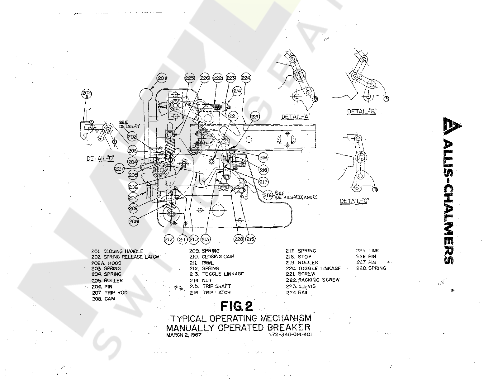
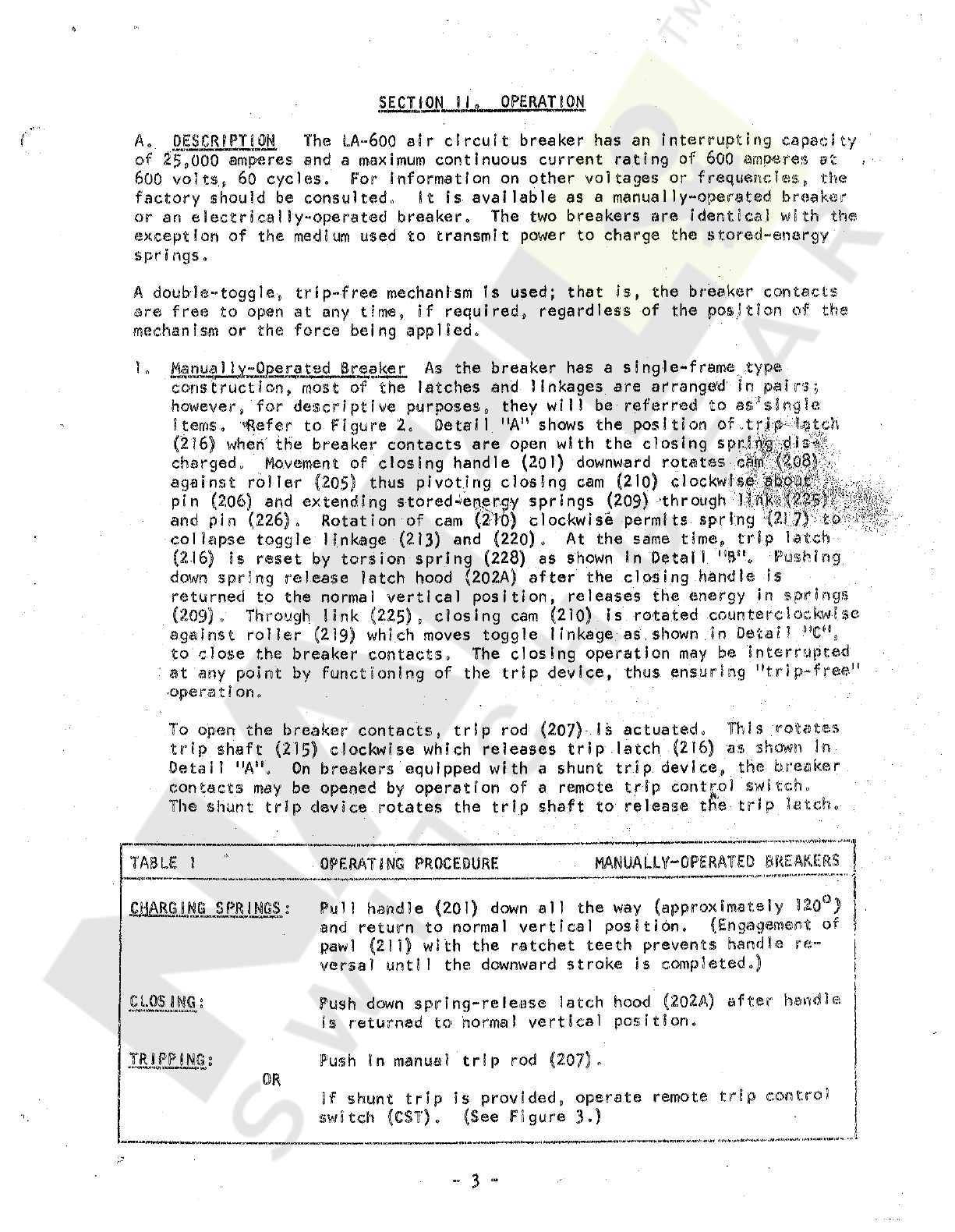
L
Manually
-
Operated
Breaker
As
the
breaker
has
a
single
-
frame
type
construction
,
most
of
the
latches
and
linkages
are
arranged
in
pairs
;
however
,
for
descriptive
purposes
,
they
will
be
referred
to
as
:
'
s
irvg
!
e
items
,
«
Refer
to
Figure
2
.
Detail
"
A
"
shows
the
position
of
..
trjfk
%
tch
(
216
)
when
the
breaker
contacts
are
open
with
the
closing
charged
.
Movement
of
closing
handle
(
20
)
)
downward
rotates
against
roller
(
205
)
thus
pivoting
closing
cam
(
210
)
clockw
|
;
«
^
|
^
M
^
^
;
Wv
.
pin
(
206
)
and
extending
stored
^
e
^
roy
springs
(
209
)
’
through
I
Iff
and
pin
(
226
)
,
Rotation
of
cam
(
2
T
0
)
clockwise
permits
sprIng
^
21
$
J
5
'
collapse
toggle
linkage
(
213
)
and
(
220
)
.
At
the
same
time
,
trip
latch
(
2.16
)
Is
reset
by
torsion
spring
(
228
)
as
shown
in
Detail
"
Bn
„
Pushing
down
spring
release
latch
hood
(
202
A
)
after
the
closing
handle
is
returned
to
the
normal
vertical
position
,
releases
the
energy
in
springs
(
209
)
,
Through
link
(
22.5
)
,
closing
cam
(
210
)
is
rotated
counterclockwise
against
roller
(
219
)
which
moves
toggle
linkage
as
.
shown
in
Detail
"
C
*
1
,
to
close
the
breaker
contacts
.
The
closing
operation
may
be
interrupted
at
any
point
by
functioning
of
the
trip
device
,
thus
ensuring
"
tr
i
p
-
.
f
ree
,
!
-
operation
.
To
open
the
breaker
contacts
,
trip
rod
trip
shaft
(
215
)
c
1
ockwlse
which
releases
trip
.
latch
(
2
(
6
)
as
shown
In
Detail
"
A
"
.
On
breakers
equipped
with
a
shunt
trip
device
,
the
breaker
contacts
may
be
opened
by
operation
of
a
remote
trip
control
switch
,
,
The
shunt
trip
device
rotates
the
trip
shaft
to
release
the
trip
latch
.
7
)
-
Is
actuated
.
This
rotates
MANUALLY
“
0
PERATED
6
REAKER
$
TABLE
1
OPERATING
PROCEDURE
i
ti
miimvft
.
MM
WA
*
*
*
«
«
*
«
I
n
*
fTm
’
l
*
*
*
*
#
*
*
*
"
*
*
K
*
.
•
«
1
H
Puli
handle
(
201
)
down
all
the
way
(
approximately
320
)
j
and
return
to
normal
vertical
position
.
(
Engagement
of
j
paw
)
(
211
)
with
the
ratchet
teeth
prevents
handle
re
-
versal
until
the
downward
stroke
is
completed
.
)
1
Push
down
spring
-
release
latch
hood
(
2
,
02
A
)
after
handle
is
returned
to
norma
!
vertical
position
.
Push
tn
manual
trip
rod
(
207
)
»
J
If
shunt
trip
Is
provided
,
operate
remote
trip
control
(
See
Figure
3
.
)
sm
&
uiLswm
-
-
CLOSING
:
TRIPPING
:
!
*
*
*
*
»«
r
»
o
OR
switch
(
CST
)
.
“
MW
-
3
“
Courtesy of NationalSwitchgear.com

(
*
’
A
ALLIS
“
CHALM
ERS
CONTROL
SWITCH
-
234
.
FLAT
SPRING
235
.
GEAR
236
.
PINS
237
TOGGLE
LINKAGE
238
.
MOTOR
GEAR
-
BOX
PINION
239
.
MOTOR
240
.
GEAR
SEGMENT
:
241
.
PIN
202
.
SPRING
RELEASE
LATCH
202
A
.
HOOD
207
TRIP
ROD
'
210
.
CLOSING
CAM
225
.
LINK
.
230
.
SPRING
-
POSITION
SWITCH
231
.
ARM
•
232
.
MOTOR
CUT
-
OFF
SWITCH
233
.
PLUNGER
FIG
.
2
A
TYPICAL
OPERATING
MECHANISM
|
ELECTRICALLY
OPERATED
BREAKE
72
-
340
-
017
-
4
01
MARCH
10
,
1967
f
-
I
-
LCS
i
T
-
r
ID
-
*
-
*
-
-
lo
8
r
o
&
2
A
1
5
4
3
/
N
/
s
®
©
©
3
O
J
-
3
P
9
I
o
7
-
N
T
0
^
toeb
u
\
t
V
10
9
4
=
a
^
b
-
^
Yl
-
J
~
o
I
«
7
t
?
AH
XI
Xft
5
-
4
TRANSFORMERS
\
MAGNETIC
.
/
TrtlP
COIL
}
F
*
,
Tf
.
°
6
o
'
TERMINAL
BLOCK
TYPICAL
WIRING
OIACRAM
FOR
EL
.
ECTRICAL
.
LY
OPERATED
BREAKERS
FIG
.
3
•
b
S
*
'
>
«
<
*
3
-
401
WAftOW
fO
,
1967
Courtesy of NationalSwitchgear.com
The
mechanism
of
the
electrically
-
operated
2
»
Electrica
11
v
-
Qperated
Breaker
Mr
.
ftiu
Ml
MKAWUW
enKWUWinWlrtiiMl
.
v
/
ttWWWoiWrtrfMinMWM
"
breaker
is
the
same
as
that
of
the
manually
-
operated
breaker
except
that
the
manual
closing
handle
is
replaced
by
an
electric
motor
and
the
gear
system
.
f
Refer
to
Figures
2
A
and
3
.
Movement
of
the
control
switch
(
N
)
located
on
the
front
of
the
breaker
to
the
"
ON
"
position
*
when
the
control
circuit
is
energized
,
wi
11
start
the
automatic
closing
cycle
.
Motor
gear
box
pinion
(
238
)
rotates
gear
(
235
)
counterclockwise
,
and
pins
(
236
)
move
across
the
top
of
flat
biasing
spring
(
234
)
.
This
raises
toggle
linkage
(
237
)
«
ver
center
and
positions
gear
(
235
)
to
mesh
with
gear
segment
(
240
)
*
Since
this
gear
segment
is
attached
to
closing
cam
(
210
)
,
the
stored
-
energy
springs
are
charged
and
latched
in
the
same
sequence
as
described
in
the
previous
section
.
The
lower
extension
of
closing
cam
(
210
)
engages
a
roller
on
toggle
linkage
(
237
)
to
disengage
gear
(
235
)
from
gear
segment
(
240
)
after
the
stored
-
energy
springs
are
latched
In
the
charged
position
by
spring
-
release
latch
(
202
)
,
Spring
-
position
switch
(
230
)
(
SPS
b
)
is
actuated
to
the
open
position
by
arm
(
231
)
attached
to
link
(
225
)
as
the
stored
-
energy
springs
approach
the
charged
position
.
This
switch
initiates
the
spring
recharging
cycle
and
Is
connected
in
parallel
with
motor
cut
-
off
switch
(
£
32
)(
88
a
)
which
is
open
initially
#
closes
while
the
motor
charges
the
springs
,
and
opens
when
the
springs
are
charged
with
the
gearing
disengaged
.
The
1
motor
cut
-
off
switch
is
actuated
by
the
movement
of
plunger
(
233
)
over
pins
(
236
)
,
Approximately
twelve
seconds
are
required
for
completion
of
the
spring
charging
cycle
.
The
breaker
may
now
be
closed
by
pushing
down
spring
«
release
latch
hood
(
2
Q
2
A
)
as
In
the
manually
-
operated
breaker
,
or
it
may
be
closed
electri
-
cally
through
remote
close
control
switch
spring
-
release
coil
(
SRC
)
which
moves
pin
(
241
)
in
a
counterclockwise
direction
to
trip
spring
release
latch
hood
(
202
A
)
and
spring
-
release
latch
(
202
)
,
The
"
Y
"
coll
Is
energized
simultaneously
with
the
spring
-
release
coil
and
causes
the
"
Y
"
contact
to
open
the
circuit
to
the
motor
.
Since
the
"
Y
"
relay
will
remain
energized
as
long
as
the
remote
close
control
swi
tch
(
CSC
)
is
held
closed
,
"
Y
1
"
contact
keeps
the
motor
.
!
ci
rcul
t
open
to
prevent
"
pumping
"
or
repeated
attempts
to
charge
the
.
stored
-
energy
springs
when
the
breaker
Is
closing
.
This
switch
energizes
After
the
stored
-
energy
springs
are
discharged
,
they
are
automatically
recharged
as
long
as
the
control
circuit
is
energized
,
and
the
control
Is
in
the
"
ON
"
position
.
Figure
3
shows
the
spring
-
position
swi
tch
switch
(
SPSjfrb
)
closed
to
complete
the
motor
control
circuit
as
it
would
be
when
the
springs
are
discharged
.
M
UJ
*
*
»
A
*
«
\
*
*
W
*
I
»
«
*
*
AI
'
Wi
ELECTRICALLY
-
OPERATED
BREAKERS
TABLE
2
OPERATING
PROCEDURE
Move
control
switch
(
N
)
on
Charging
Springs
:
Energize
control
circuit
,
front
of
breaker
to
"
ON
"
position
After
springs
are
charged
,
actuate
remote
close
control
switch
(
CSC
)
.
Push
down
spring
-
release
latch
hood
(
202
A
)
.
X
:
#
Actuate
remote
trip
control
switch
(
CST
)
Push
In
manual
trip
rod
(
207
)
.
Closing
;
OR
Tripping
2
ca
i
|
>
Courtesy of NationalSwitchgear.com
ALLIS
-
CHALMERS
a
h
u
^
-
LIFTING
BAR
l
|
1
'
II
CSJ
a
RACK
'
OUT
c
:
:
r
:
i
i
ZL
7
.
LT
.
7
ID
rL
c
.
.
.
.
(
%
)
(
402
MNTERL
0
CK
SLIDE
i
1
-
i
!
rb
(
§
)
\
~
~
LL
_
~
.
dk
CONTROL
SWITCH
^
FRONT
VIEW
(
ELECTRICALLY
OPER
,
"
-
*
-
“
“
BREAKERS
)
.
J
OJ
r
@
CUBICLE
FIXED
PIN
r
c
>
,
iv
J
o
v
*
RACKING
.
CLEVIS
(
408
,
rs
-
1
“
1
:
1
l
lr
~
X
*
I
TRIP
ROD
.
•
t
i
i
r
n
CV
^
J
l
J
UT
.
0
®
)
*
SITUR
LOC
K
CAM
(
408
rlNTERL
0
CK
TRIP
SHAFT
-
MOT
SIDE
VIEW
FIG
.
4
TYPICAL
RACKING
MECHANISM
&
DRAWOUT
INTERLOCK
72
-
440
-
010
-
40
I
APRIL
3
,
1967
Courtesy of NationalSwitchgear.com
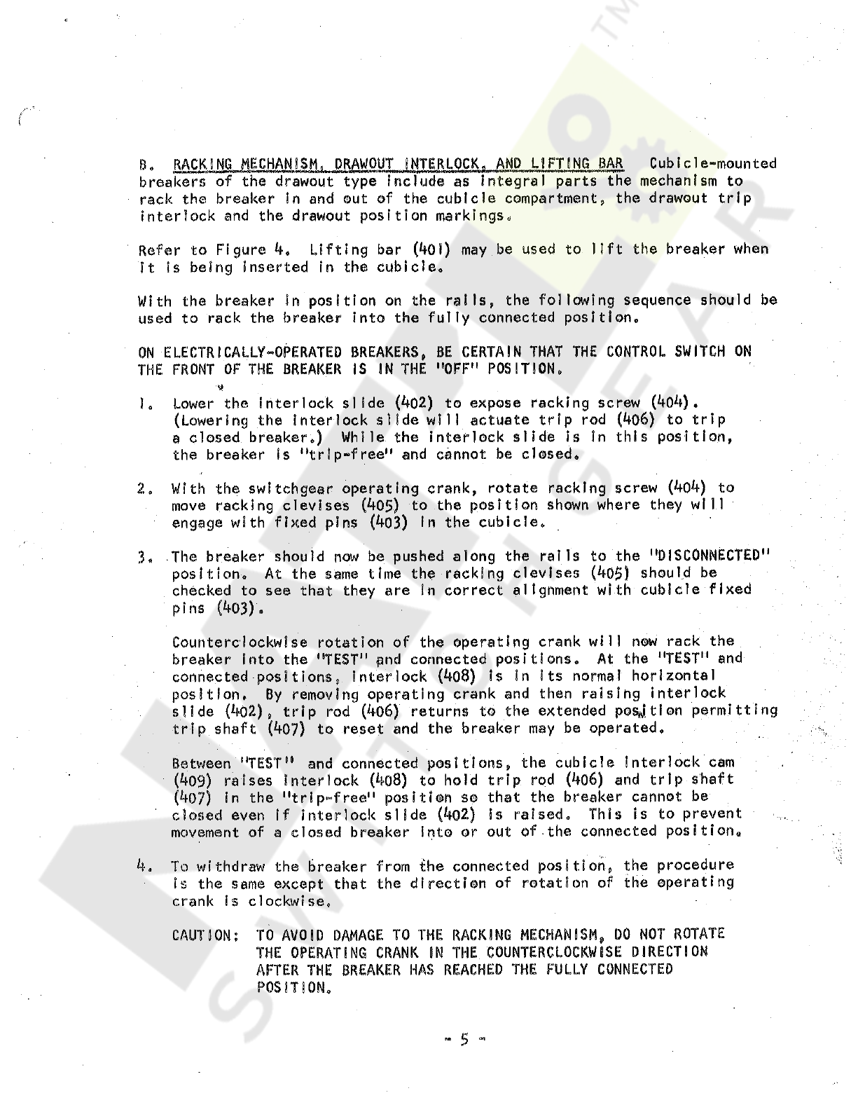
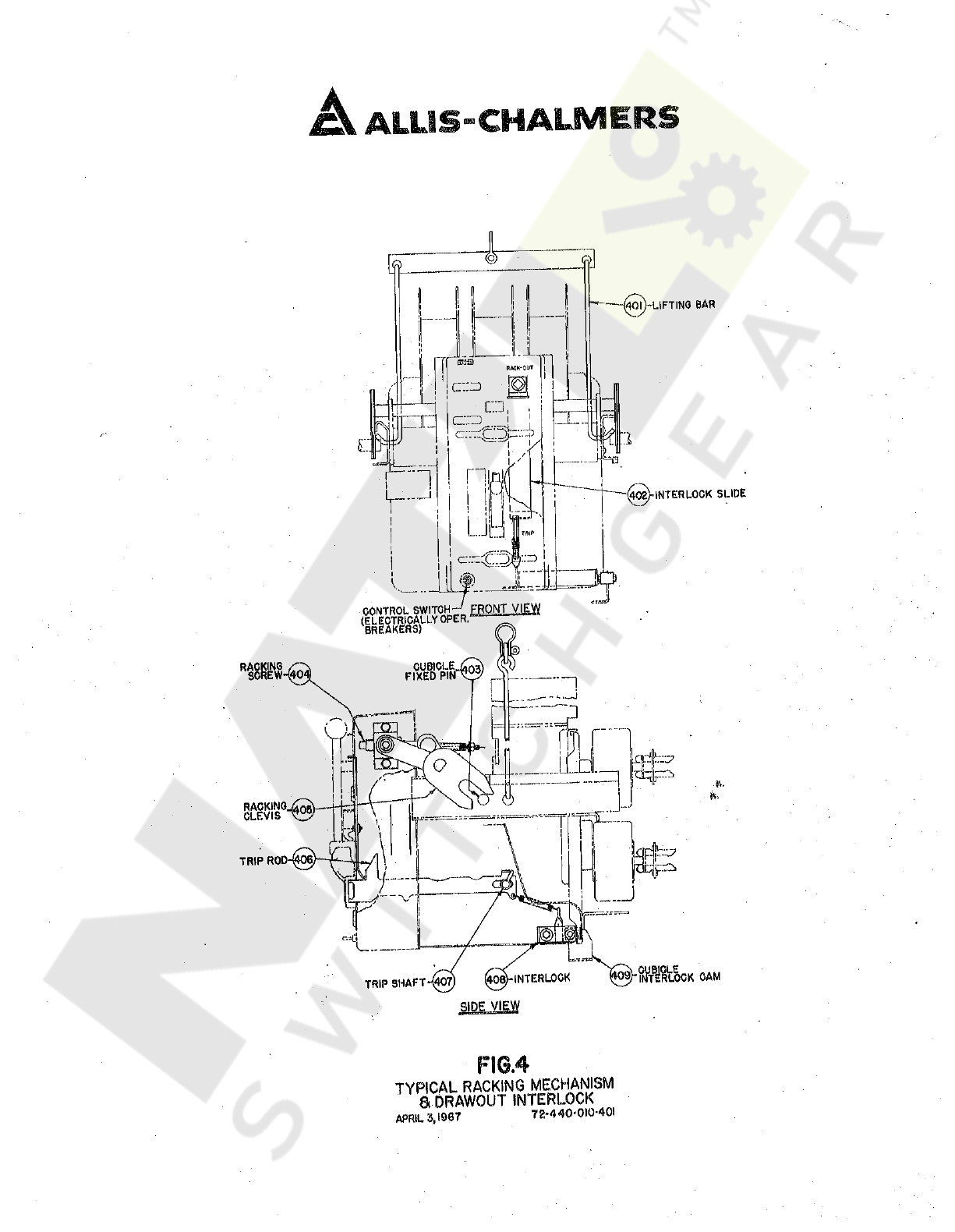
8
.
RACKING
MECHANISM
,
DRAWOUT
INTERLOCK
.
AND
LIFTING
BAR
Cubicle
-
mounted
breakers
of
the
drawout
type
Include
as
Integral
parts
the
mechanism
to
rack
the
breaker
In
and
out
of
the
cubicle
compartment
,
the
drawout
trip
interlock
and
the
drawout
position
markings
.
Lifting
bar
(
401
)
may
be
used
to
lift
the
breaker
when
Refer
to
Figure
4
«
it
is
being
inserted
in
the
cubicle
.
With
the
breaker
in
position
on
the
rails
used
to
rack
the
breaker
into
the
fully
connected
position
.
the
following
sequence
should
be
ON
ELECTRICALLY
-
OPERATED
BREAKERS
,
BE
CERTAIN
THAT
THE
CONTROL
SWITCH
ON
THE
FRONT
OF
THE
BREAKER
IS
IN
THE
"
OFF
"
POSITION
.
M
1
.
Lower
the
interlock
slide
(
402
)
to
expose
racking
screw
(
404
)
.
(
Lowering
the
Interlock
slide
will
actuate
trip
rod
(
406
)
to
trip
a
closed
breaker
.
)
While
the
interlock
slide
is
in
this
position
,
the
breaker
Is
"
trip
-
free
"
and
cannot
be
closed
.
2
.
With
the
switchgear
operating
crank
,
rotate
racking
screw
(
404
)
to
move
racking
clevises
(
405
)
to
the
position
shown
where
they
will
engage
with
fixed
pins
(
403
)
In
the
cubicle
.
3
.
The
breaker
should
now
be
pushed
along
the
rails
to
the
"
DISCONNECTED
"
position
.
At
the
same
time
the
racking
clevises
(
405
)
should
be
checked
to
see
that
they
are
in
correct
alignment
with
cubicle
fixed
pins
(
403
)
.
Counterclockwise
rotation
of
the
operating
crank
will
now
rack
the
breaker
Into
the
"
TEST
"
pnd
connected
positions
.
At
the
"
TEST
"
and
connected
positions
,
interlock
(
4
o
8
)
is
in
its
normal
horizontal
position
.
By
removing
operating
crank
and
then
raising
interlock
slide
(
4
-
02
)
,
trip
rod
(
406
)
returns
to
the
extended
position
permitting
trip
shaft
(
407
)
to
reset
and
the
breaker
may
be
operated
.
Between
"
TEST
"
1
and
connected
positions
,
the
cubicle
interlock
cam
(
409
)
raises
interlock
(
4
o
8
)
to
hold
trip
rod
(
4
o
6
)
and
trip
shaft
(
4
o
?
)
in
the
"
trip
-
free
"
position
so
that
the
breaker
cannot
be
closed
even
if
interlock
slide
(
4
o
2
)
is
raised
.
This
is
to
prevent
movement
of
a
closed
breaker
into
or
out
of
the
connected
position
.
4
.
To
withdraw
the
breaker
from
the
connected
position
,
the
procedure
is
the
same
except
that
the
direction
of
rotation
of
the
operating
crank
is
clockwise
.
/
*
'
J
TO
AVOID
DAMAGE
TO
THE
RACKING
MECHANISM
,
DO
NOT
ROTATE
THE
OPERATING
CRANK
IN
THE
COUNTERCLOCKWISE
DIRECTION
AFTER
THE
BREAKER
HAS
REACHED
THE
FULLY
CONNECTED
POSITION
.
CAUT
J
ON
:
-
5
-
Courtesy of NationalSwitchgear.com
SECTION
.
III
.
MAINTENANCE
AND
ADJUSTMENTS
MWrMomHwiM
n
>
g
*
M
morjM
^
oiw
.
X
'
l
•
n
WWW
y
.
wrri
a
*
>
»
HCTWiiwauM
*
'
i
Occasional
checking
and
cleaning
of
the
breaker
will
promote
long
and
trouble
-
free
service
,
A
periodic
inspection
and
servicing
at
intervals
of
six
months
or
one
year
should
be
included
In
the
maintenance
routine
.
Circuit
breakers
located
in
areas
subject
to
acid
fumes
,
cement
dust
,
or
other
abnormal
conditions
,
require
more
frequent
servicing
,
After
a
severe
overload
interruption
,
the
breaker
should
be
inspected
.
If
the
circuit
breaker
Is
not
operated
during
extended
periods
,
it
should
not
remain
in
either
the
closed
or
open
position
any
longer
than
six
months
.
Maintenance
opening
and
closing
operations
should
be
made
to
ensure
freedom
of
movement
of
all
parts
.
A
suggested
procedure
to
follow
during
maintenance
inspections
is
given
below
:
A
.
MAINTENANCE
x
.
De
-
energize
the
primary
and
control
circuits
.
i
.
Rack
cubicle
-
mounted
breakers
of
the
drawout
type
to
the
disconnected
pos
S
t
i
on
»
2
O
3
.
Discharge
stored
-
energy
springs
.
4
.
Remove
arc
chutes
and
examine
for
burned
,
cracked
,
or
broken
parts
.
5
.
Wipe
the
contacts
with
a
clean
cloth
saturated
with
a
non
-
toxic
cleaning
fluid
.
6
»
Replace
badly
burned
or
pitted
contacts
.
(
See
paragraph
£
)
.
7
.
Wipe
all
Insulated
parts
with
a
clean
cloth
saturated
with
a
non
-
toxic
cleaning
fluid
,
8
.
Bearing
p
.
lns
and
other
sliding
or
rotating
surfaces
should
be
cleaned
and
then
coated
with
a
light
film
of
grease
(
See
paragraph
B
)
,
9
»
Operate
the
breaker
manually
in
maintenance
closing
position
(
see
to
check
latch
and
linkage
movement
,
10
.
Check
breaker
adjustments
(
see
paragraph
D
)
.
8
,
LUBRICATION
Lubrication
should
be
a
part
of
the
service
procedure
.
Needle
bearings
are
packed
with
grease
and
should
require
no
further
attention
.
0
)
d
grease
should
be
removed
from
bearing
pins
and
other
rotating
or
sliding
surfaces
,
and
they
should
be
wiped
with
a
thin
film
of
petroleum
-
oi
1
-
base
precision
-
equipment
grease
similar
to
BEACON
P
-
290
.
Greasing
should
be
done
with
care
because
excess
grease
tends
to
collect
foreign
matter
which
in
time
may
make
operation
sluggish
and
may
affect
the
dielectric
strength
of
insula
-
ting
members
.
ft
.
paragraph
KtmWK
»
,
«
«
<
I
»
1
TOMf
.
UlhCVU
HXKWI
3
.
M
)
6
“
Courtesy of NationalSwitchgear.com

ALLIS
-
CHALMERS
(
REFER
SECTION
MIC
PG
.
7
)
MAINTENANCE
CLOSING
HANDLE
RELEASE
LATCH
HOOD
205429
i
TYPICAL
MAINTENANCE
CLOSING
HANDLE
ELECTRICALLY
OPERATED
BREAKERS
i
<
!
STEP
1
STEP
2
205450
MANUAL
TRIP
ROD
(
REFER
FIG
.
2
DETAIL
"
D
"
)
(
REFER
TABLE
5
,
PG
.
7
)
TYPI
CAL
MAINTENANCE
CLOSING
HANDLE
PROCEDURE
FIGURE
5
MAINTENANCE
CLOSING
Courtesy of NationalSwitchgear.com
f
.
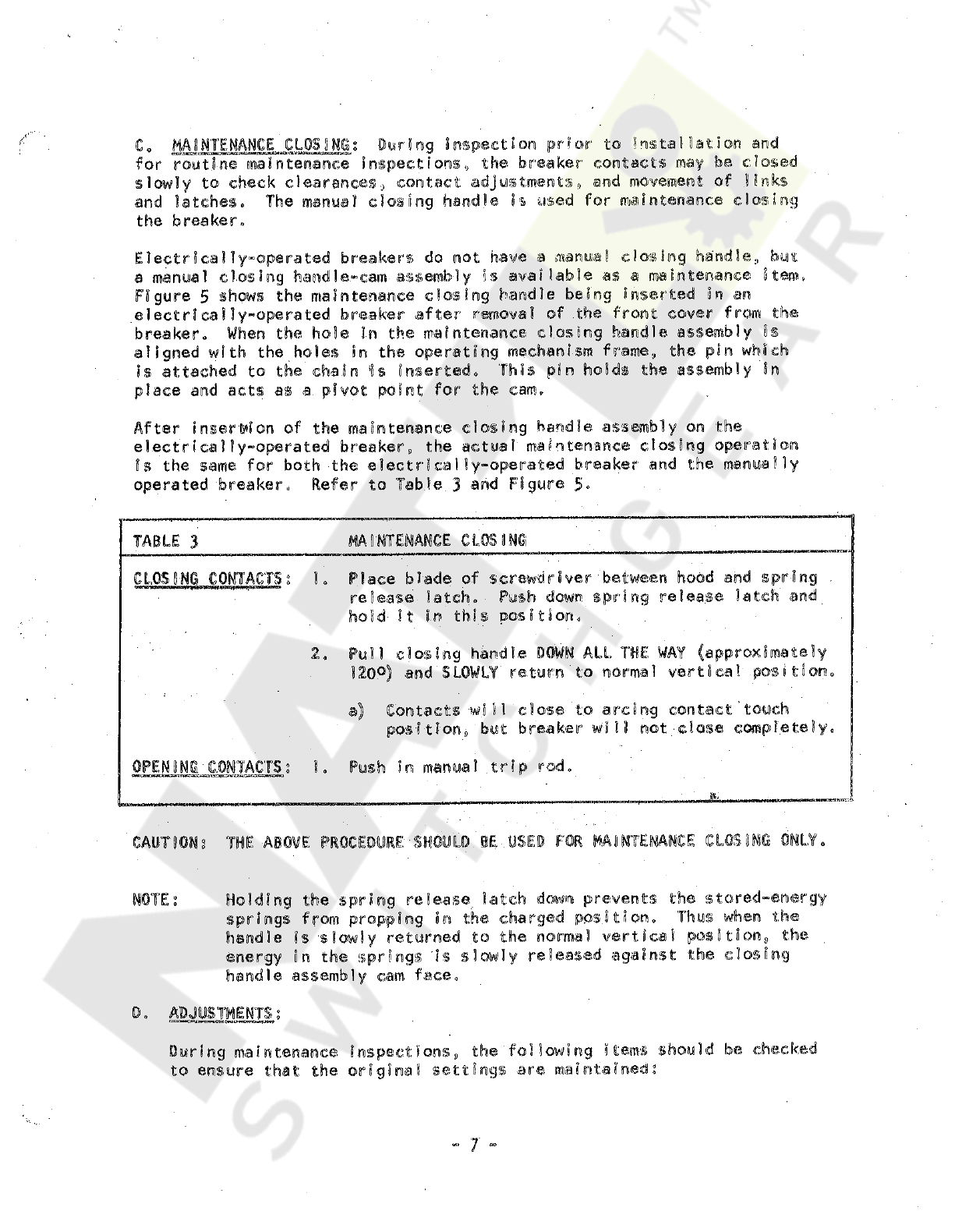
Co
MAINTENANCE
CLOSUMGs
During
inspection
prior
to
Installation
and
for
routine
maintenance
inspections
,
the
breaker
contacts
may
be
closed
slowly
to
check
clearances
,
contact
adjustments
,
and
movement
of
links
and
latches
.
The
manual
closing
handle
Is
used
for
maintenance
closing
the
breaker
.
Electrlea
11
y
“
Operated
breakers
do
not
have
a
manual
closing
handle
.
,
but
a
manual
closing
handle
-
cam
assembly
5
s
available
as
a
maintenance
Stem
.
Figure
5
shows
the
maintenance
closing
handle
being
Inserted
in
an
electrically
-
operated
breaker
after
removal
of
the
front
cover
from
the
breaker
.
When
the
hole
In
the
maintenance
closing
handle
assembly
is
aligned
with
the
holes
in
the
operating
mechanism
frame
,
the
pin
which
is
attached
to
the
chain
fs
inserted
.
This
pin
holds
the
assembly
in
place
and
acts
as
a
pivot
point
for
the
cam
.
After
insert
'
s
on
of
the
maintenance
closing
handle
assembly
on
the
electrically
-
operated
breaker
,
the
actual
maintenance
closing
operation
fs
the
same
for
both
the
electrically
-
operated
breaker
and
the
manually
operated
breaker
.
Refer
to
Table
3
and
Figure
5
.
TABLE
3
MAINTENANCE
CLOSING
CLOSING
CONTACTS
2
Place
blade
of
screwdriver
between
hood
and
spring
.
release
latch
.
Push
down
spring
release
latch
and
hold
it
in
this
position
.
Pull
closing
handle
DOWN
ALL
THE
WAY
(
approximately
120
°
)
and
SLOWLY
return
to
normal
vertical
position
.
a
)
Contacts
wi
11
close
to
arcing
contact
'
touch
position
,
but
breaker
will
not
-
close
completely
.
2
,
OPENING
CONTACTS
;
Push
In
manual
.
trip
rod
*
&
Biwwr
.
:
!
THE
ABOVE
PROCEDURE
SHOULD
BE
USED
FOR
MAINTENANCE
CLOSING
ONLY
.
CAUTION
?
NOTE
:
Holding
the
spring
release
latch
down
prevents
the
stored
-
energy
springs
from
propping
in
the
charged
position
.
Thus
when
the
handle
is
slowly
returned
to
the
normal
vertical
position
,
the
energy
in
the
springs
Is
slowly
released
against
the
closing
handle
assembly
cam
face
.
D
.
ADJUSTMENTS
?
RmMiac
^
ji
*
imC
»
lCNOi
-
'
*
“
During
maintenance
inspections
,
the
following
items
should
be
checked
to
ensure
that
the
original
settings
ar
©
maintained
;
7
-
Courtesy of NationalSwitchgear.com
'
•
'
ft
.
'
V
\
)
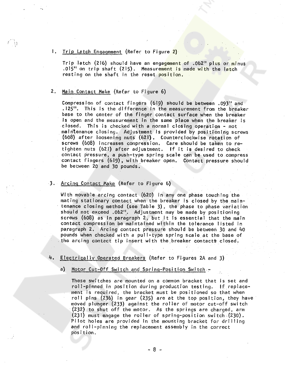
Trip
Latch
Engagement
(
Refer
to
Figure
2
)
Trip
latch
(
2
)
6
)
should
have
an
engagement
of
,
062
"
plus
or
minus
.
015
"
on
trip
shaft
(
215
)
»
Measurement
is
made
with
the
latch
resting
on
the
shaft
in
the
reset
position
,
1
.
Main
Contact
Make
(
Refer
to
FIgure
6
)
2
.
Compression
of
contact
fingers
(
6
,
125
"
.
base
to
the
center
of
the
finger
contact
surface
when
the
breaker
Is
open
and
the
measurement
in
the
same
place
when
the
breaker
Is
closed
.
This
is
checked
with
a
normal
closing
operation
»
not
maintenance
closing
.
Adjustment
is
provided
by
positioning
screws
(
608
)
after
loosening
nuts
(
621
)
,
Counterclockwise
rotation
of
increases
compression
.
Care
should
be
taken
to
re
-
after
adjustment
.
If
it
is
desired
to
check
should
be
between
.
093
"
and
This
is
the
difference
in
the
measurement
from
the
breaker
screws
tighten
nuts
contact
pressure
,
,
a
push
-
type
spring
scale
can
be
used
to
compress
contact
fingers
(
619
)
»
with
breaker
open
.
Contact
pressure
should
be
between
20
and
30
pounds
.
Arcing
Contact
Make
(
Refer
to
Figure
6
)
3
.
With
movable
arcing
contact
mating
stationary
contact
when
the
breaker
is
closed
by
the
main
-
tenance
closing
method
should
not
exceed
,
062
"
.
screws
in
any
one
phase
touching
the
ee
Table
3
)
*
the
phase
to
phase
variation
Adjustment
may
be
made
by
positioning
as
in
paragraph
2
»
but
it
is
essentia
)
that
the
main
contact
compression
be
maintained
within
the
tolerance
listed
in
paragraph
2
»
Arcing
contact
pressure
should
be
between
30
and
40
pounds
when
checked
with
a
pull
-
type
spring
scale
at
the
base
of
the
arcing
contact
tip
insert
with
the
breaker
contacts
closed
.
4
«
,
Electricaily
Operated
Breakers
Motor
Cut
-
Off
Switch
and
Sprinq
-
Pos
?
tion
Switch
-
er
to
Figures
2
A
and
3
)
These
switches
are
mounted
on
a
common
bracket
that
is
set
and
ace
-
roll
-
pinned
in
position
during
production
testing
*
ment
i
$
required
*
the
bracket
must
be
positioned
so
that
when
roll
plus
(
236
)
In
gear
(
235
)
are
at
the
top
position
*
they
have
moved
plunger
(
233
)
against
the
roller
of
motor
cut
-
off
switch
(
232
)
to
shut
off
the
motor
.
As
the
springs
are
charged
*
arm
(
231
)
must
engage
the
roller
of
.
spring
-
position
.
switch
;
(
230
)
•
Pilot
holes
are
provided
In
the
mounting
bracket
for
drilling
and
roll
-
pinning
the
replacement
assembly
I n
the
correct
Courtesy of NationalSwitchgear.com
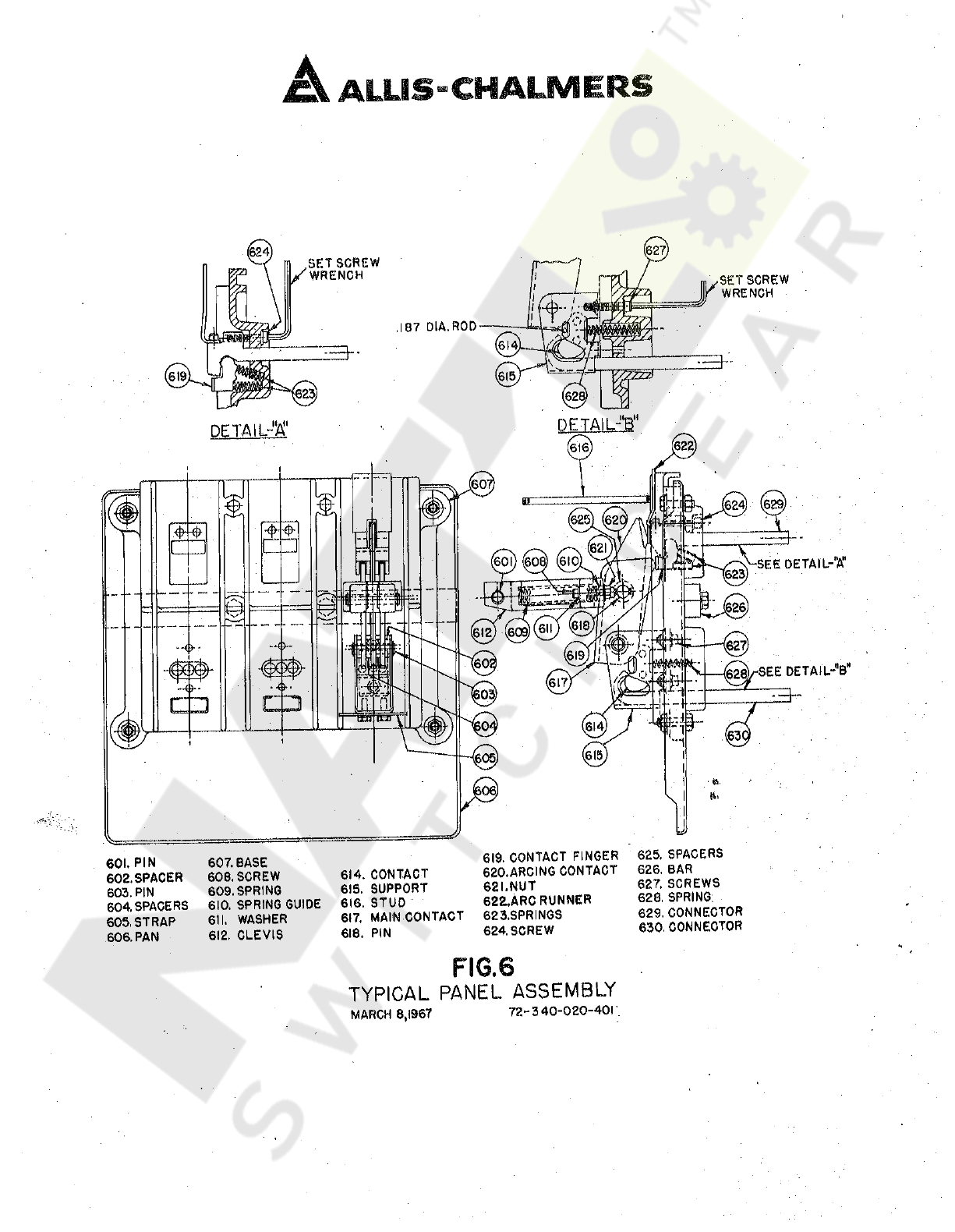
A
ALUS
-
CHALMERS
(
624
.
SETSCREW
/
WRENCH
I
.
SETSCREW
/
WRENCH
DETA
1
LJ
<
BM
DETAILS
o
SEE
DETAIL
-
V
.
-
'
•
V
S
3
~
0
~
SEE
DETAIL
-
B
"
CD
"
©
605
,
&
-
•
J
)
625
.
SPACERS
626
.
BAR
627
.
SCREWS
628
.
SPRING
.
629
.
CONNECTOR
630
.
CONNECTOR
619
.
CONTACT
FINGER
620
.
ARCING
CONTACT
621
.
NUT
622
.
.
ARC
RUNNER
623
.
SPRINGS
624
.
SCREW
601
.
PIN
602
.
SPACER
603
.
PIN
604
.
SPACERS
605
.
STRAP
606
.
PAN
607
.
BASE
606
,
SCREW
609
.
SPRING
610
.
SPRING
GUIDE
611
.
WASHER
612
.
CLEVIS
614
.
CONTACT
615
.
SUPPORT
616
.
STUD
6
(
7
.
MAIN
CONTACT
618
.
PIN
FIG
.
6
TYPICAL
PANEL
ASSEMBLY
72
-
3
40
-
020
-
401
MARCH
8
,
1667
Courtesy of NationalSwitchgear.com
E
„
CONTACT
REPLACEMENT
Refer
to
Figure
6
,
The
contact
structure
consists
of
main
current
carrying
contacts
and
arcing
contacts
arranged
so
that
initial
contact
make
and
final
contact
break
is
by
means
of
the
arcing
contacts
.
The
main
contacts
are
not
subject
to
arcing
.
The
actual
contact
surfaces
are
clad
with
an
alloy
facing
which
greatly
reduces
mechanical
wear
and
arc
erosion
,
,
When
inspection
of
the
alloy
facing
indicates
that
the
contacts
should
be
replaced
,
it
should
be
noted
that
hinge
contact
fingers
(
614
)
,
main
contact
fingers
(
619
)
and
arcing
contacts
(
620
)
are
spring
loaded
.
There
-
fore
,
care
must
be
exercised
in
removal
and
installation
of
any
of
the
contacts
.
1
,
Main
Contact
Fingers
With
the
breaker
contacts
open
and
the
stored
-
energy
springs
dis
-
charged
,
main
contact
fingers
screws
(
624
)
enough
to
relieve
the
compression
on
springs
(
623
)
as
shown
in
Oetall
"
A
"
,
There
are
two
springs
behind
each
finger
and
it
is
important
that
they
be
positioned
properly
upon
reinstallation
.
If
difficulty
is
experienced
in
correctly
positioning
these
springs
,
the
upper
and
lower
primary
disconnects
(
119
-
Figure
1
)
may
be
removed
from
each
phase
and
the
breaker
Inverted
to
rest
on
the
ends
of
connectors
(
629
)
and
(
630
)
,
may
be
removed
by
loosening
After
the
contact
fingers
are
replaced
,
connector
positioned
In
the
center
of
the
slot
in
the
molded
base
to
assure
correct
alignment
of
the
primary
disconnect
fingers
.
2
.
Stationary
Arcing
Contact
The
stationary
arcing
contact
is
a
part
of
connector
(
629
)
and
may
be
replaced
by
proceeding
as
above
.
In
this
case
,
screws
must
be
removed
.
However
,
to
provide
clearance
for
removal
of
connector
(
629
)
first
insert
a
.
187
"
diameter
rod
at
least
2
"
long
through
the
opening
in
support
(
615
)
as
shown
in
Detail
"
B
"
»
It
may
be
necessary
to
compress
contact
(
614
)
opposite
arcing
contact
(
620
)
In
order
to
Insert
the
rod
.
This
will
hold
hing
^
contact
fingers
(
614
)
in
position
to
permit
removal
of
pin
(
603
)
.
After
removal
of
pin
(
603
)
»
main
contact
(
617
)
and
arcing
contact
can
be
positioned
so
that
connector
(
629
)
can
be
removed
.
should
be
3
.
Hinge
Contact
Fingers
Hinge
contact
fingers
(
6
!
4
)
may
be
removed
as
follows
;
Remove
top
screw
(
627
)
from
support
(
615
)
and
replace
it
with
a
.
250
-
20
screw
at
least
1.5
"
long
.
Remove
lower
screw
(
62
?
)
and
then
gradually
back
off
the
1
,
5
"
screw
as
shown
In
Detail
"
B
"
,
to
relieve
the
loading
from
springs
(
628
)
,
The
hinge
contact
fingers
can
now
be
removed
.
To
provide
easier
access
to
the
hinge
contact
fingers
,
pin
(
603
)
may
be
removed
after
the
loading
is
relieved
from
springs
-
(
62
,
8
)
.
Be
certain
to
replace
the
1
,
5
"
long
screws
with
the
original
screws
after
replacement
of
the
contact
fingers
.
-
9
-
Courtesy of NationalSwitchgear.com
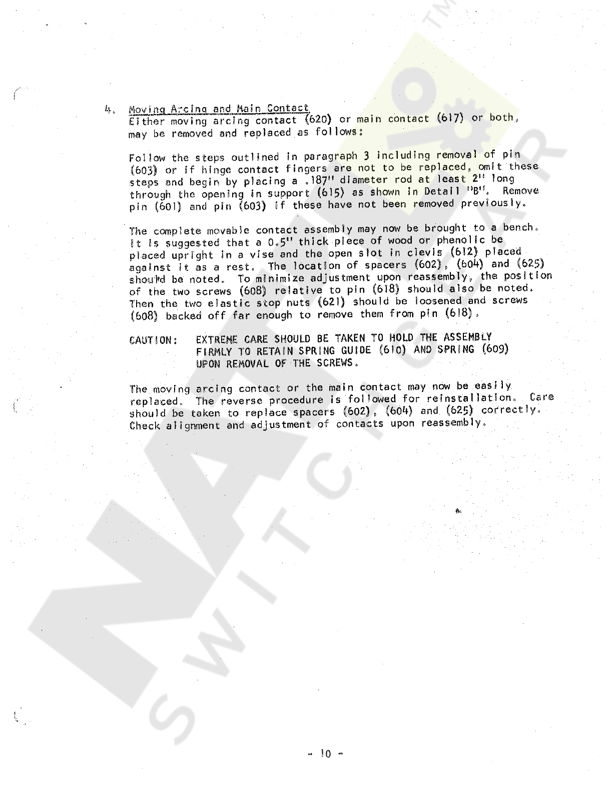
4
.
Movinq
Arclna
and
Main
Contact
I R
*
WAJ
-
ito
*
*
*
*
m
.
i
—
i
.
>
.
ww
«
wiin
»
»
n
>
.
-
Either
moving
arcing
contact
(
620
)
or
main
contact
(
617
)
or
both
,
,
may
be
removed
and
replaced
as
follows
?
Follow
the
steps
outlined
In
paragraph
3
including
removal
of
pin
(
603
)
or
if
hinge
contact
fingers
are
not
to
be
replaced
,
omit
these
steps
and
begin
by
placing
a
.
187
M
diameter
rod
at
least
2
"
long
through
the
opening
in
support
(
615
)
as
shown
in
Detail
"
B
*
'
.
Remove
pin
(
601
)
and
pin
(
603
)
if
these
have
not
been
removed
previously
.
The
complete
movable
contact
assembly
may
now
be
brought
to
a
bench
.
It
is
suggested
that
a
0
„
5
,
!
thick
piece
of
wood
or
phenolic
be
placed
upright
in
a
vise
and
the
open
slot
in
clevis
(
612
)
placed
against
it
as
a
rest
.
The
location
of
spacers
(
602
)
,
(
604
)
and
(
623
)
shou
+
d
be
noted
.
To
minimize
adjustment
upon
reassembly
,
the
position
of
the
two
screws
(
608
)
relative
to
pin
(
618
)
should
also
be
noted
.
Then
the
two
eiastic
stop
nuts
(
621
)
should
be
loosened
and
screws
(
608
}
backed
off
far
enough
to
remove
them
from
pin
(
618
)
,
EXTREME
CARE
SHOULD
BE
TAKEN
TO
HOLD
THE
ASSEMBLY
FIRMLY
TO
RETAIN
SPRING
GUIDE
(
610
)
AND
SPRING
(
609
)
UPON
REMOVAL
OF
THE
SCREWS
.
CAUTION
;
The
moving
arcing
contact
or
the
main
contact
may
now
be
easily
replaced
.
The
reverse
procedure
is
followed
for
reinstallation
.
Care
should
be
taken
to
replace
spacers
(
602
)
,
(
604
)
and
(
625
)
correctly
.
Check
alignment
and
adjustment
of
contacts
upon
reassembly
.
fa
10
Courtesy of NationalSwitchgear.com

SECTS
ON
IV
.
STATIC
OVERCURRENT
TRIP
DEVICE
MnftjoK
(
A
.
INTRODUCTION
The
Allis
-
Chalmers
Static
Overcurrent
Trip
Devices
are
completely
static
;
that
is
there
are
no
moving
parts
or
contacts
.
The
circuits
of
the
device
are
designed
for
light
loading
of
components
and
are
temperature
compensated
for
accuracy
and
stability
of
calibration
over
wide
temperature
ranges
for
Indefinite
periods
of
time
.
The
static
overcurrent
trip
devices
,
which
replace
the
electro
-
mechanicaI
series
overcurrent
trip
devices
,
perform
the
same
function
with
a
higher
degree
of
accuracy
and
versatility
.
In
common
with
series
overcurrent
trip
devices
,
all
energy
for
operation
is
obtained
from
overload
or
fault
current
.
No
batteries
or
other
external
power
sources
are
required
.
The
complete
static
overcurrent
trip
system
consists
of
three
current
trans
-
formers
,
one
per
phase
,
mounted
on
the
circuit
breaker
primary
connectors
,
a
release
magnet
,
and
the
static
overcurrent
trip
device
.
This
system
operates
to
Mrip
the
circuit
breaker
when
a
system
overload
condition
exceeds
a
pre
-
selected
value
of
current
.
Tripping
will
occur
after
a
predetermined
time
delay
or
instantaneously
depending
upon
the
adjustment
selected
and
the
magnitude
of
the
overload
.
The
static
trip
device
contains
three
current
transformers
which
provide
a
small
low
voltage
secondary
current
proportional
to
the
circuit
breaker
primary
current
.
The
secondary
of
each
transformer
Is
connected
in
series
with
a
power
supply
transformer
and
an
auxiliary
transformer
.
The
output
of
the
power
supply
transformers
Is
rectified
to
provide
D
,
C
,
energy
to
the
release
magnet
trip
coil
and
also
a
regulated
D
.
C
.
power
supply
to
operate
,
transistor
circuits
.
Potentiometers
or
rheostats
connected
in
parallel
with
the
auxiliary
transformers
provide
an
A
.
C
.
signal
voltage
proportional
to
the
primary
current
.
This
acts
as
the
intelligence
input
for
the
device
,
and
the
magnitude
of
this
A
.
C
,
voltage
determines
whether
or
not
the
breaker
will
trip
and
the
time
delay
before
tripping
.
The
relation
between
this
A
.
C
.
signal
voltage
and
the
primary
current
can
be
varied
by
adjusting
the
potentiometers
to
set
the
minimum
primary
current
at
which
tripping
will
occur
,
This
is
the
pick
-
up
adjustment
.
A
transistor
trigger
circuit
prevents
operation
of
the
timing
circuit
unless
the
signal
exceeds
95
%
of
pick
-
up
value
.
If
the
trigger
has
operated
,
a
capacitor
will
charge
gradually
to
a
voltage
which
causes
the
static
switch
If
at
any
time
to
operate
,
energize
the
trip
coil
,
and
trip
the
breaker
before
the
static
switch
actually
operates
,
the
primary
current
decreases
to
95
%
or
less
of
the
set
pick
-
up
,
the
trigger
will
turn
off
and
reset
will
take
place
,
Some
minor
variations
in
pick
-
up
and
time
delay
may
be
expected
with
temperature
fluctuations
from
an
ambient
of
~
4
o
°
C
,
to
an
ambient
of
55
°
C
.
A
typical
breaker
rating
plate
Is
shown
in
Figure
7
A
.
The
maximum
rated
amperes
is
determined
by
the
current
transformers
mounted
on
the
circuit
breaker
primary
connectors
.
The
maximum
current
available
Is
limited
by
the
circuit
breaker
frame
size
.
Since
the
static
overcurrent
trip
device
components
are
calibrated
in
terms
of
transformer
secondary
current
,
the
same
device
can
be
used
with
any
of
the
groups
of
current
transformers
available
.
11
Courtesy of NationalSwitchgear.com
Other manuals for LA-600
2
Other Allis-Chalmers Circuit Breaker manuals

Allis-Chalmers
Allis-Chalmers LA-600 User manual

Allis-Chalmers
Allis-Chalmers MA-75B User manual

Allis-Chalmers
Allis-Chalmers LA-25 Installation manual

Allis-Chalmers
Allis-Chalmers MA-75 User manual

Allis-Chalmers
Allis-Chalmers LA-1600 User manual

Allis-Chalmers
Allis-Chalmers LA 3000 User manual

Allis-Chalmers
Allis-Chalmers FB-500A-FC-750A User manual

Allis-Chalmers
Allis-Chalmers LA-1600 User manual

Allis-Chalmers
Allis-Chalmers LA-600 User manual


