manuals.online logo
Brands
  1. Home
  2. •
  3. Brands
  4. •
  5. Allis-Chalmers
  6. •
  7. Circuit Breaker
  8. •
  9. Allis-Chalmers MA-75B User manual

Allis-Chalmers MA-75B User manual

-
*
r
\
'
ALLIS
-
CHALMERS
INBTRUCTIOry
BOOK
y
*
•
j
TYPE
"
D
"
MOVABLE
PORTION
MA
-
75
/
150
/
250
B
RUPTAIR
MAGNETIC
POWER
CIRCUIT
BREAKER
AND
AUXILIARY
EQUIPMENT
(
STOREO
-
ENERGY
OPERATOR
)
>
JUNE
,
1967
BWX
-
6657
-
3
i
!
%
•
Courtesy of NationalSwitchgear.com
ALLIS
-
CHALMERS
TABLE
OF
CONTENTS
(
SE
-
4
,
STOREO
ENERGY
OPERATOR
)
SECTION
NO
.
,
CONTENTS
PART
I
DESCRIPTION
GENERAL
METHOD
OF
ARC
INTERRUPTION
1
.
2
PART
2
ADJUSTMENTS
2
I
GENERAL
•
siS
*
SE
-
4
SCORED
ENERGY
OPERATOR
PART
3
3.1
DESCRIPTION
OF
OPERATOR
DRIVING
SYSTEM
SPRING
LINKAGE
4
-
BAR
BREAKER
CLOSING
LINKAGE
CHARGING
SPRINGS
CLOSING
BREAKER
OPENING
BREAKER
MANUALLY
SLOW
-
CLOSING
BREAKER
MAIN
TOGGLE
ROLL
TRIP
LATCH
CLOSING
LATCH
TRIPPING
AND
CLOSING
SOLENOID
AUXILIARY
EQUIPMENT
AUXILIARY
SWITCH
INTERLOCK
PLUNGER
SPRING
DISCHARGE
OPERATOR
CONTROL
RESET
RELAY
3.1
(
a
)
3.1
(
b
)
31
(
c
)
32
3
*
3
3.4
3.5
3.6
•
*
.
3.7
3
-
8
t
.
JK
3
-
9
3
10
3
11
3.12
3.12
A
3.13
3.14
.
V
*
rO
i
PART
4
DISCONNECT
SECTION
r
-
to
sS
4
1
BREAKER
MECHANISM
CONTACTS
SERVICING
CONTACTS
BREAKER
TIMING
ARCING
CONTACT
HINGE
JOINT
CONTACT
PRESSURE
ON
HINGE
JOINT
CONTACT
ALIGNMENT
CONTACT
LEAD
CONTACT
STROKE
4
,
2
4
2
A
4
3
4
,
4
4.5
4
,
6
4
7
u
8
ARC
CHUTE
ASSEMBLY
PART
5
51
ARC
CHUTE
ASSEMBLY
PHASE
BARRIERS
TILTING
ARC
CHUTES
BARRIER
STACKS
5
2
5
-
3
5.4
Courtesy of NationalSwitchgear.com
ALUS
-
CHALMERS
••
>
?
*
t
j
.
•
)
•
-
LIST
OF
ILLUSTRATIONS
TYPE
"
D
"
MOVABLE
PORTION
MA
-
75
/
150
/
250
B
RUPTAIR
MAGNETIC
POWER
CIRCUIT
BREAKER
AND
AUXILIARY
EQUIPMENT
(
STORED
ENERGY
OPERATOR
)
72
-
420
-
036
-
401
FIGURE
1
TYPICAL
MAGNETIC
BREAKER
71
-
401
-
520
-
401
71
-
401
-
522
-
401
FIGURE
2
TYPICAL
ARC
CHUTE
FIGURE
3
TYPICAL
STUD
&
SUPPORT
FIGURE
4
SE
-
4
STORED
ENERGY
OPERATOR
72
-
320
-
047
-
401
FIGURE
4
A
72
-
420
-
041
-
401
TYPICAL
SPRING
DISCHARGE
FIGURE
8
72
-
420
-
020
-
401
TYPICAL
CONTROL
SWITCH
71
-
301
-
758
-
401
FIGURE
11
TYPICAL
AUXILIARY
SWITCH
205439
FRONT
SIDE
VIEW
OF
TYPE
"
D
"
,
4.16
kv
1200
AMP
AIR
MAGNETIC
CIRCUIT
BREAKER
205438
VIEW
SHOWS
APPLICATION
OF
FIFTH
WHEEL
ON
TYPE
"
D
"
AIR
MAGNETIC
CIRCUIT
BREAKER
SIDE
VIEW
OF
TYPE
"
D
"
,
4.16
kv
,
1200
AMP
AIR
MAGNETIC
CIRCUIT
BREAKER
217530
\
$
217525
TILTING
BACK
ARC
CHUTE
1
205442
MANUALLY
CHARGING
SPRINGS
K
Courtesy of NationalSwitchgear.com
>
:
ALLIS
“
CHALMERS
^
T
-
STr
*
?
.
-
*
-
•
=
-
j
-
;
v
'
f
;
•
—
-
;
,
v
:
;
>
Vr
1
-
v
:
i
'
*
-
o
:
;
-
.
.
#
#
*
#
•
:
<
>
'
*
•
'
%
>
•
r
V
•
-
-
i
*
>
>
'
i
,
i
.
,
_
«
»
v
v
•
?
.
-
,
-
>
•
:
f
*
Er
*
a
$
-
>
.
v
.
.
’
-
,
i
A
"
>
-
I
£
v
*
-
?
:
*
•
:
*
*
••
?
-
-
*
.
.
?
.
i
(
*
•
<
M
*
<
5
'
>
:
?
•
r
.
j
..
i
.
-
-
i
.
vi
-
4
.
*
*
vv
7
'
-
*
-
•
:
<
•
»
*
:
•
i
-
V
.
*
*
*
*
-
*
•
:
ti
#
•
r
•
;
-
:
•
'
•
•
v
.
;
-
;
/
*
*
l
-
&
*
:
4
.
‘
a
.
*
.
*
>
,
»
4
.
£
r
*
A
t
,
*
*
*
*
W
*
1
t
-
'
l
<
f
i
«
c
.
.
l
-
i
.
-
.
ifir
'
/
Jkii
.
:
;
.
<
i
.
,
3
fc
.
.
*
>
«
S
;
..
*
i
*
/
:
&
:
<
£
M
•
>
•
-
«
••
.
*
•
.
=
^
-
*
W
'
JfY
'
M
"
'
!
*
-
J
»
]
*
?
*
,
*
*
•
-
.
?
*
•
5
f
-
-
S
^
V
-
Am
roj
.
—
-
<
t
-
>
:
:
;
*
'
f
-
vi
-
fc
*
.
*
«
••
*
*
V
*
fU
*
.
*
*
.
•
:
.
-
i
*
l
;
-
£
.
=
'
*
;
*
-
*
*
-
*
-
-
*
s
jQ
£
=
>
*
*
•
“
•
'
S
-
v
*
t
:
'
.
*
-
<
i
-
j
*
A
*
v
-
.
^
pr
fir
;
*
.
«
*
-
*
•
-
*
.
f r
-
*
'
*
*
iM
/
4
*
•
*
•
•
fr
*
*
*
*
.
*
*
*
-
*
!
*
*
'
*
•
•
«
]
•
*
.
*
fete
*
.
*
*
-
*
.
*
.
-
*
&
-
-
&
A
<
*
--
&
&
•
i
*
.
^
*
v
.
|
l
-
s
t
-
«
/
4
<
i
>
I
4
-
:
v
>
•
>
T
-
yi
-
^
i
*
i
f
?
•
r
]
f
'
v
^
••
-
>
'
*
•
-
*
'
•
»
’
•
*
"
ife
»
*
*
•
4
•
&
•
.
?
•
»
.
-
v
v
-
r
;
•
«
ipa
*
<
#
.•
<
>
•
*
’
•
v
-
-
1
i
'
-
y
.
.
!
-
—
.
i
-
*
•
*
A
-
•
•
-
V
>
M
*
*
-
f
-
"
•
^
.
jT
'
S
'
:
•
>
rf
.
-
si
.
-
»
.
<
s
-
.
-
.
v
.
*
-
•
:
*
•
:
-
4
jr
-
r
-
»
:
?
-
iS
.
:
i
.
.
A
'
•
i
-
'
-
?
f
f
•
’
S
4
•
-
>
i
*
-
:
*
:
>
*
»
:
<
*
Tr
:
;
5
'
-
"
-
-
-
-
f
.
-
v
Vi
:
;
*
-
•
>
:
t
.
s
.
'
•
•
•
:
=
?
••
«
-
«
-
r
.
-
s
-
-
‘
.
S
''
A
.
'
-
t
-
i
-
»
-
..
-
S
.
;
r
=
-
i
:
.
•
*
;
*
\
^
>
‘
:
•
-
I
-
:
r
*
:
'
<
-
#
:
•
/
r
.
5
-
^
•
'
'
-
•
.
-
.
.
•
-
•
•
'
'
'
-
~
'
1
"
*
•
-
5
-
5
W
<
•
t
4
-
1
-
^
-
!
V
•
:
S
'
«
.
I
i
.
r
-
.
-
v
-
.
.
;
?
'
.
'
•
>
|
.
.
-
.
*
.
•
a
.
'
-
f
i
!
.
.•
:
>
V
-
i
.
4
-
-
i
<
<
•
f
v
V
i
:
?
"
--
,
?
-
:
j
?
•
i
-
-
S
1
y
;
.
-
;
•
-
.
.
-
-
<
x
s
-
r
•
rf
>
’
:
f
.
is
-
>
*
-
-
:
\
•
:
-
.
;
'
i
-
i
;
-
5
:
:
-
.
i
>
•
»
.
-
.
•
*
.
-
i
-
•
?
,
:
'
’
r
~
.
-
•
•
S
'
ji
!
..
?
'
'
.
'
•
'
.
-
•
sT
'
?
-
.
=
fi
‘
t
*
'
^
•
vi
y
'
i
*
>
•
>
v
,
-
SK
-
•
:
J
-
.
‘
>
-
v
^
>
•
i
-
•
'
»
=
:
'
'
'
r
’
*
•
•
'
4
'
"
*
.
wp
#
.
*
.
*
\
-
K
:
-
X
-
-
.
-
--
;
,
.
v
^
-
-
vi
.
.
’
.
y
-
r
'
-
'
-
•
>
4
•
•
•
ivi
.
'
l
;
v
-
.
^
-
;
-
i
>
;
.
>
-
=
.
*
.
s
•
-
'
-
-
••
'
:
*
*
»
?
¥
•
*
*
*
4
-
vs
=
4
^
1
'
•
f
•
:
Vv
;
1
.
.
-
.
*
.
.•
V
:
:
,
•.
*
•
:
••
v
V
it
V
,
FRONT
SIDE
VIEW
OF
TYPE
"
D
"
,
4.16
kv
1200
AMP
AIR
MAGNETIC
CIRCUIT
BREAKER
205439
Courtesy of NationalSwitchgear.com
ALUS
CHALMERS
[
•
T
'
*
W
;
<
-
i
v
*
*
lU
«
-
'
t
*
y
a
•
*
*
»
M
«
^
.
.
..
*
A
-
*
.
*
*
*
*
.
*
«
*
•
»
to
i
i
.
.
i
.
.
#
,
.
r
-
*
*
b
*
'
•
i
*
*
•
*
.
.
#
*
*
9
’
)
-
*
*
*
f
*
*
1
,
»
p
*
•
#
*
A
f
-
3
*
>
U
*
>
t
<
*
'
i
i
'
*
*
*
'
*
*
•
'
*
•
•
<
*
'
*
•
*
*
M
-
‘
*
•
*
•
*
»
;
•
*
.
«
«
*
•
*
••
*
<
*
*
•
.
%
’
«
J
:
\
A
.
-
fk
;
;
ttj
;
.
;
;
:
|
f
w
”
'
*
r
'
U
«
ft
§
f
•
v
*
t
*
r
A
t
t
m
,
.
,
'
!
l
*
»
fr
.
*
-
V
;
*
•
>
*
;
^
?
:
;
:
:
:
-
:
r
!
.
ir
.
tiiiM
-
W
-
*
it
*
•
•
»
»
.
4
*
i
•
5
•
'
k
'
^
-
*
•
*
-
*
H
*
»
.
*
"
"
>
*
>
sffi
&
EwnnBjR
.
>
*
»
*
•
*
%
•
#
&
!
'
•
”
y
*
«
'
*
•
*
-
•
«
'
•
»
=
.
4
'
*
•
<
•
•
,
(
:
»
<
*
•
*
•
>
.
•
*
*
•
*
.
^
*
.
,
#
«
K
$
W
*
;
?
*
•
>
•
•
>
*
*
•
¥
*
III
H
f
*
»
V
•
«
-
4
S
<
.
*
•
«
.
(
a
\
>
.
.
-
*
*
*
r
l
'
.
#
*
4
>
t
»
^
«
?
«
>
•
*
1
fc
.
f
A
t
•
.
-
fv
*
*
>
<
#
4
*
‘
&
j
*
>
>
*
*
*
*
A
*
?
»
"
t
if
$
*
h
H
.
+
4
iit
*
(
&&
&
*
4
•
-
!
1
.
•
*
f
1
5
V
•
<
i
-
•
••
*
4
*
*
*
<
f
I
“
-
«
r
•
'
*
-
.
t
»
<
»
"
i
-
*
*
Si
.
fij
*
.
<
?
»
i
-
i
»
«
5
S
v
*
I
l
'
V
>
'
J
'
L
t
•
-
•
*
sf
•
1
*
V
h
*
t
•
>
»
-
i
>
i
i
>
.
f
«
'
*
?
^
*
-
5
J
-
.
4
H
'
>
-
3
t
>
.
-
e
»
t
>
-
r
v
*
r
^
v
.
<
-
;
«
,
*
.
-
«
>
i
:
4
‘
*
?
*
*
*
*
*
*
•
>
t
J
#
W
tar
-
A
—
!
'
;
j
.
;
^
^
ly
,
M
*
*
4
rffn
7
>
?
»
.
#
:
%
*
a
f
t
a
y
i
iTT
«
T
•
!
»
!
iBte
i
%
<
•
l
.
)
If
f
•
*
?
»
»
.
4
if
'
#
?
•
•
4
.
*
~
b
*
*
’
*
'
*
^
-
*
>
>
6
'
-
•
*
*
»
’
*
«
t
<
N
>
.
*
,
*
<
*
k
A
/
v
4
«
rfSS
>
"
"
»
'
‘
-
rus
>
'
*
t
,
,
;
?
<
‘
«
L
;
tt
:
fraptm
v
•
*
»
J
»
»
•
jpS
fc
S
-
Vij
-
'
ijf
}
«
^
a
'
.
<
*
'
*
/
>
!
a
5
#
-
V
»
.
«
jr
,
r
»
'
/
?
ft
5
l
33
^
/
>
«
»
»
.
<
.
«
•
*
<
*
/
*
ii
*
*
?
-
1
•
«
v
>
.
-
•
>
’
?
t
&
!
i
<
.
*
>
-
^
V
*
«
•
5
.
-
t
-
^
1
‘
<
T
c
s
tlv
t
T
?
.
V
:
?
/
|
•
i
>
A
|
;
;
L
*
-
:
r
.
.
via
m
t
205438
:
•
•
•
-
•
“
’
"
"
"
"
ssr
.
ra
-
^
i
;
Courtesy of NationalSwitchgear.com
A
ALLIS
-
CHALMERS
s
>
_
•
>
&
.
@
«
!
'
•
’
rU
'
J
;
*
H
I
:
1
fV
:
:
'
•
r
•
fc
$
te
;
i
-
:
-
V
.
vt
;
jto
:
m
••
>
/
.
•
W
:
>
?
}
*
:
v
!
.
N
\
5
|
V
{
f
-
\
h
\
:
>
-
iv
i
-
i
:
>
>
:
•
i
>
2
"
[
4
*
H
M
:
?
>
<
3
&
:
i
V
vi
*
:
t
.
-
•
£
:
•
*
•
4
S
556
s
«
ft
r
"
A
«
-
;
V
*
ir
.
?
:
'
ft
-
;
A
^
(
f
-
-
•
v
f
-
'
r
-
.
‘
'
ft
r
>
-
.
?
iftv
i
•
'
•.
ft
>
4
•
•
s
'
i
-
Pi
ik
f
'
i
i
1
*
"
:
i
V
'
i
-
ft
.
>
:
.
'
%
r
,
*
*
.
«
=
?
W
-
'
f
*
'
‘
ft
*
>
'
;
••
4
-
:
?
)
t
*
.
o
}
*
ii
'
ft
>
•
'
:
:
V
?
•
-
£
I
•
'
•
ft
tft
•
>
•
v
,
?
;
}
vi
tii
k
-
ft
:
i
'
*
•
r
5
••
it
f
:
.
i
:
r
r
'
*
i
i
M
i
.
t
-
'
ft
'
14
f
>
:
•
>
^
2
v
S
-
.
»
s
.
?
•
;
f
-
;
.
f
-
y
4
Is
V
•
i
Pi
t
-
N
!
'
•
ft
1
}
;
j
‘
ni
<
>
vr
'
m
i
-
*
&
:
m
m
hi
mt
?
r
-
*
&
-
v
-
t
-
V
.
ft
#
i
«
'
?
-
>
•
•
.
-
.
ft
ift
•
«
-
A
•
r
\
»
-
•
;
.
«
i
'
4
H
5
*
iftft
'
.
ft
?
-
'
A
?
r
,
:
:
v
ft
*
.
4
:
^
4
-
i
'
-
ft
ift
^
^
•
ft
i
'
ft
if
*
I
'
ft
V
*
i
-
‘
^
?
fc
'
?
r
-
if
--
^
*
t
<
ft
?
:
ft
'
•
i
i
4
rtV
;
r
-
'
i
i
ft
?
>
i
'
?
-
:
-
M
V
.
<
-
/
.
fv
ftft
ih
-
j
£
»
•
f
^
ft
;
Si
s
;
v
»
:
=
/
5
ey
«
*
'
1
ft
*
'
i
i
S
‘
•
•
:
;
si
:
i
;
-
‘
•
f
-
m
li
-
K
IP
©
l
;
isw
>
.
s
I
i
-
f
f
'
i
-
4
yl
F
*
-
'
jp
S
HU
:
,
?
iy
.
4
v
#
f
?
til
>
V
&
»
ik
-
%
i
-
P
.
1
.
*
r
-
A
i
y
-
•
V
•
7
Side
view
of
Type
0
,
4.16
Magnetic
Circuit
Breaker
,
kv
,
1200
Amp
.
,
Air
Outer
Phase
Barrier
Removed
.
217530
'
<
.
Courtesy of NationalSwitchgear.com
A
ALUS
-
CHALMERS
1
V
4
r
.
I
4
r
%
“
I
?
iv
.
f
!
l
1
'
v
4
•
f
II
S
V
'
:
ii
m
s
£
:
vjf
gc
$
»
.
»
.
.
.
,
•
•
•
•
r
.
,
}
3
s
-
<
'
if
!
:
;
J
•
r
f
i
/
t
-
:
i
<
•
i
=
.
-
‘
f
4
217525
Arc
Chute
Assembly
of
Type
D
,
4.16
kv
,
1200
Amp
Air
Magnetic
Circuit
Breaker
is
tilted
back
for
easy
assembly
of
contacts
.
t
-
*
•
Courtesy of NationalSwitchgear.com
.
\
ALLIS
-
CHALMERS
205442
MANUALLY
CHARGING
SPRINGS
)
"
v
>
Courtesy of NationalSwitchgear.com
PART
I
.
DESCRIPTION
1.1
GENERAL
The
Al
1
is
-
Chalmers
RUPTAIR
movable
portion
consists
of
a
magnetic
circuit
breaker
for
metal
-
clad
switchgear
application
,
with
auxi
1
iary
equipment
suitably
arranged
for
best
function
and
easy
installation
.
As
part
of
standard
equipment
,
each
order
is
furnished
with
one
maintenance
closing
device
for
solenoid
operated
breakers
or
a
charging
crank
for
stored
energy
operated
units
.
The
RUPTAIR
magnetic
circuit
breaker
differs
essentially
from
oil
breakers
and
air
-
blast
breakers
in
that
it
does
not
depend
on
any
stored
medium
such
as
oil
or
compressed
air
for
arc
interruption
.
The
com
^
fnent
parts
,
of
the
breaker
are
mounted
in
a
structural
steel
frame
.
The
operator
,
the
operating
shaft
,
and
connecting
links
are
mounted
on
the
lower
section
of
the
breaker
frame
and
are
well
shielded
.
The
horizontal
terminal
studs
,
which
are
insulated
with
flame
retardent
tubing
,
extend
through
the
breaker
bracket
and
support
the
other
parts
of
the
electrical
circuit
.
Interruption
occurs
within
the
arc
chute
assemblies
which
are
mounted
at
the
top
,
over
the
contact
structures
.
1.2
METHOD
OF
ARC
INTERRUPTION
Interruption
is
accomplished
in
air
at
atmospheric
pressure
,
with
the
aid
of
a
self
-
induced
magnetic
blowout
field
and
air
draft
.
At
the
time
the
trip
coil
is
energized
,
current
is
being
carried
through
the
main
contacts
.
As
the
movable
contact
assembly
separates
from
the
stationary
contact
assembly
,
the
current
transfers
very
quickly
from
the
main
contacts
to
the
arcing
contacts
,
thus
keeping
the
main
contact
erosion
to
a
minimum
.
(
For
breakers
equipped
with
tertiary
contacts
,
the
current
transfers
from
the
mains
,
to
the
tertiary
and
then
to
the
arcing
contacts
.
)
As
the
movable
contact
assembly
continues
its
stroke
,
the
arcing
contacts
part
,
drawing
a
power
arc
,
which
is
transferred
first
to
the
stationary
end
arc
runner
then
to
the
moving
end
arc
runner
.
The
transfer
of
the
arc
to
the
arc
runners
establishes
the
full
flow
of
current
through
the
blowout
coils
,
setting
up
the
magnetic
field
which
,
in
accompaniment
with
natural
thermal
effects
of
the
heated
arc
,
the
configuration
of
the
current
carrying
circuit
,
etc
.
,
tend
to
force
the
arc
upward
into
the
barrier
stack
.
The
cool
surfaces
of
the
barrier
stack
cool
and
deionize
the
arc
,
while
the
"
Vee
"
siots
in
the
stack
reduce
its
cross
section
and
elongate
it
.
The
arc
runners
are
made
of
wide
,
heavy
material
for
maximum
heat
dissi
-
pation
and
to
minimize
metal
vaporization
.
To
facilitate
interruption
of
low
currents
,
a
puffer
assembly
provides
a
movement
of
air
through
the
contact
area
to
aid
the
magnetic
field
in
moving
the
arc
into
the
barrier
stack
.
All
of
the
above
effects
work
together
to
increase
the
resistance
of
the
arc
and
enable
it
to
be
extinguished
at
an
early
current
zero
.
Courtesy of NationalSwitchgear.com
PART
2
.
ADJUSTMENTS
2.1
GENERAL
The
breaker
has
been
completely
set
up
,
adjusted
and
tested
at
the
factory
.
Adjustments
should
not
have
to
be
made
nor
fastenings
tightened
when
the
breaker
is
received
.
If
there
is
visible
damage
or
breakage
due
to
shipment
,
storage
or
installation
,
the
adjustments
should
be
checked
and
corrected
,
if
necessary
,
before
breaker
is
operated
electrically
.
Manual
operation
(
use
maintenance
closing
device
)
of
breaker
sifould
be
used
for
preliminary
operation
to
see
that
all
parts
are
free
and
work
smoothly
.
The
bushings
and
other
insulating
parts
should
be
clean
and
dry
.
All
contact
surfaces
should
be
inspected
to
see
that
they
are
clean
and
smooth
.
(
Do
not
dress
silver
surfaces
)
.
Removal
of
all
phase
barriers
and
removal
or
raising
of
arc
chute
assemblies
gives
access
to
breaker
for
checking
adjustments
.
BEFORE
REMOVING
ANY
PART
,
MAKE
SURE
THAT
THE
BREAKER
AND
ITS
OPERATING
MECHANISM
IS
DISCONNECTED
FROM
ALL
ELECTRIC
POWER
AND
THAT
THIS
BREAKER
IS
IN
THE
OPEN
POSITION
.
CAUTI
ON
:
I
Courtesy of NationalSwitchgear.com
TART
3
-
SE
-
&
STORED
ENERGY
OPERATOR
t
«
t
>
i
fl
H
•
VuA
.
Vr
'
M
*
.
1
^
11
*
+
r
*
.
ivf
»
u
*
'
«
rl
»
5
^
»
*
One
*
*
'
/
s
OPERATOR
.
(
Pig
.
4
}
The
-
stored
energy
operator
consists
of
three
systems
:
fa
)
the
dri
system
,
(
b
)
the
spring
linkage
,
,
and
(
c
)
the
4
-
bar
closing
linkage
SYSTERNS
are
disengaged
from
each
other
except
while
performing
the
specific
function
;
thus
,
,
the
driving
system
and
spring
linkage
arc
completely
free
of
each
other
except
when
the
spring
linkage
is
re
and
ready
to
re
charged
.
Similarly
the
spring
linkage
and
closing
linkage
are
free
of
each
other
except
during
a
cl
os
ing
**
Sperat
ion
.
3
.
I
fa
)
DRIVING
^
SYSTEM
The
driving
system
consists
of
a
gearmotor
driving
a
pinion
(
4
-
2
)
which
,
in
turn
,
drives
two
spur
gears
(
4
-
3
)
.
A
free
-
swinging
cram
it
is
driven
by
a
pin
(
4
-
fastened
to
the
spur
gear
;
and
it
drives
the
spring
linkage
,
3
.
i
(
b
)
This
system
consists
of
four
closing
springs
(
4
-
6
)
,
two
links
(
4
-
7
)
two
links
(
4
-
9
)
,
one
link
(
4
-
10
)
,
two
links
(
4
-
11
)
and
crank
(
4
-
12
)
.
when
the
linkage
is
reset
,
the
springs
can
be
charged
by
cranks
(
4
-
4
,
driving
the
rolls
(
4
-
24
)
fastened
to
link
(
4
-
10
)
until
links
(
4
-
9
aric
4
-
10
)
go
over
toggle
.
At
the
start
of
this
operation
,
links
(
4
-
9
)
will
be
in
tension
,
allowing
a
gap
between
latch
(
4
-
13
)
and
its
roll
However
,
part
way
through
the
charging
operation
,
as
the
springs
are
being
charged
,
the
action
of
roll
(
4
-
19
)
coming
against
latch
(
4
-
13
)
will
be
heard
.
The
action
of
links
(
4
-
9
and
4
-
10
)
going
over
toggle
will
be
heard
at
the
end
of
the
charging
operation
.
Releasing
closing
latch
(
4
-
13
)
will
free
the
closing
springs
to
drive
the
breaker
closing
1
inkage
(
see
below
)
.
During
this
operation
,
the
spring
charging
linkage
remains
over
toggle
until
near
the
end
of
its
stroke
when
the
toggle
Is
broken
by
crank
(
4
-
12
)
striking
the
kick
-
off
screw
(
4
-
32
)
.
The
spring
linkage
immediately
resets
allowing
the
breaker
closing
linkage
room
to
reset
when
tripped
.
3
J
(
c
)
4
-
BAR
BREAKER
CLOSING
LINKAGE
M
Iliir
»
»
mu
—
wip
-
niMf
w
HiHll
—
muta
-
i
*
l
»
«
This
system
consists
of
two
links
(
4
-
20
)
,
two
links
(
4
-
21
)
and
arm
(
4
-
22
)
,
It
is
always
free
to
operate
in
any
of
its
functions
as
it
is
not
secured
to
the
spring
charging
linkage
,
[
jn
the
closing
operation
the
spring
charging
linkage
drives
toggle
roll
(
4
-
19
)
over
toggle
against
stop
(
4
-
59
)
*
thus
closing
the
breaker
through
arm
(
4
-
23
)
.
Depressing
latch
(
4
-
27
)
during
a
closing
operation
prevents
the
breaker
from
closing
,
thereby
making
it
trip
free
.
t
1
#
44
«
*
W I
*
l
-
J
)
v
M
»
.
(
4
-
4
)
is
mounted
on
each
spur
gear
shaft
;
SPRING
LINKAGE
Hi
—
—
W
\
Tjs
tv
S
3
SS
\
H
ns
.
Courtesy of NationalSwitchgear.com
3
2
tHAR
61
NO
$
PRi
W
*
$
V
I
MjltM
•
»
•
•
,
i
*
»
*
*
'
*
•
v
«
«
r
»
w
ll
'
he
closing
springs
(
4
-
6
)
.
will
charge
as
soon
as
the
breaker
control
bus
is
energized
,
Should
the
springs
not
charge
,
check
the
'
notor
cx
toff
adj
us
tment
isee
Section
3
*
13
i
)
*
The
springs
can
be
manually
charged
by
inserting
the
charging
handle
down
guide
tube
(
1
-
27
)
to
engage
the
gearmot
.
or
,
Rotate
the
handle
in
the
direction
shown
until
the
spring
linkage
is
heard
to
go
over
toggle
(
see
Section
3
«
1
(
b
)
v
REMOVE
CHARGING
HANDLE
FROM
BREAKER
BEFORE
'
ENERCTZ
’
N
.
BREAKER
CONTROL
CIRCUIT
*
3.3
CLOSING
BREAKER
When
the
springs
are
fully
charged
,
the
breaker
can
be
closed
manually
by
pulling
lanyard
{
t
—
26
)
or
electrically
by
energizing
the
closing
c
i
rcu
i
t
.
.
close
the
breaker
.
This
rotates
latch
(
4
-
13
)
allowing
the
springs
(
4
-
6
;
to
34
OPENING
BREAKER
The
breaker
can
be
tripped
manually
by
depressing
trip
rod
11
-
43
.
}
or
electrically
by
energizing
the
trip
circuit
.
This
rotates
latch
(
4
-
?
.
/
)
allowing
the
closing
linkage
to
collapse
and
reset
.
The
tripping
action
described
above
can
take
place
at
any
time
during
a
closing
operation
,
either
manual
or
electrical
,
and
regardless
of
whether
or
not
the
armature
is
energized
.
Thus
the
mechanism
is
electrically
and
mechanically
trip
-
free
in
any
position
,
X
sVv
3.5
MANOALl
.
Y
SLOW
-
CLOSING
BREAKER
rs
\
s
In
order
to
check
and
make
contact
adjustments
,
the
breaker
can
be
closed
slowly
and
mechanically
held
in
any
position
of
the
closing
stroke
.
The
following
procedure
should
be
followed
.
\
«
)
Remove
breaker
-
from
cubicle
and
tilt
arc
chutes
back
.
r
*
\
Be
certain
that
control
circuit
is
open
and
closing
springs
are
discharged
.
insert
mechanism
locking
pin
into
hole
(
1
-
28
)
,
It
will
be
necessary
to
rotate
lever
(
1
-
29
)
to
allow
pin
to
pass
through
hole
.
The
pin
should
pass
behind
crank
(
1
-
30
)
and
through
hole
in
opposite
side
of
operator
frame
.
b
)
c
)
Courtesy of NationalSwitchgear.com
d
)
Insert
spring
charging
handle
into
guide
tube
(
1
-
27
!
)
ard
engage
with
gearmotor
.
Turn
handle
in
direction
opposite
to
direction
indicated
on
shield
un
t
'
i
1
res
i
stance
is
felt
.
Pull
manual
closing
lanyard
(
1
-
26
)
and
continue
turning
handle
,
The
breaker
contacts
will
slowly
close
.
AS
THE
CONTACTS
APPROACH
THE
BREAKER
CLOSE
?
EOS
"
O S
'
,
OBSERVE
THE
POSITION
OF
CRANKS
(
4
-
4
)
ON
ROUS
'
4
-
24
)
.
CARE
SHOULD
BE
TAKEN
THAT
THE
CRANKS
DO
NOT
PASS
K
THE
ROLLS
,
ALLOWING
THE
CONTACTS
TO
SNAP
OPEN
,
CAUTION
;
Since
the
motor
gears
are
self
locking
,
the
contacts
can
be
cranked
to
any
position
and
held
for
adjustment
checks
,
e
)
To
prepare
for
normal
operation
:
Trip
breaker
open
.
Remove
spring
charging
handle
.
Remove
mechanism
locking
pin
.
.
t
\
l
\
t
X
>
a
Courtesy of NationalSwitchgear.com
I
I
I
M
.
;
N
.
*
3.6
MAIN
TOGGLE
ROLL
(
Fig
.
4
)
When
the
breaker
is
in
the
closed
position
with
toggle
roll
(
4
-
15
)
against
stop
(
4
-
59
)
the
center
of
the
toggle
trol
l
(
4
-
15
)
should
be
3
/
16
to
5
/
16
beyond
the
line
of
centers
of
the
latch
roll
(
4
-
14
)
and
pin
(
4
-
30
)
.
Adjustment
is
made
by
adding
c
removing
shims
(
4
~
60
)
,
3.7
TRIP
LATCH
(
Fig
.
4
)
i
*
1
>
<
•
'
The
trip
latch
(
4
-
27
)
should
engage
its
roll
(
4
-
14
)
1
/
8
to
3
/
16
Adjustment
is
made
by
screw
Note
that
this
adjustment
affects
the
clearance
between
the
above
the
lower
edge
of
the
latch
face
.
(
4
-
65
)
.
trip
pin
(
4
-
I
7
A
)
and
the
trip
latch
(
4
-
27
)
(
see
Section
39
)
.
When
the
*
breaker
is
open
,
the
trip
latch
(
4
-
27
)
should
clear
its
latch
roll
by
1
/
64
to
3
/
64
.
Adjustment
is
made
by
screw
(
4
-
75
)
.
3.8
CLOSING
LATCH
(
Fig
.
.
4
)
I
l
!
!
The
closing
latch
(
4
-
13
)
should
engage
its
roll
(
4
-
19
)
1
/
8
to
3
/
16
Adjustment
is
made
by
screw
Note
that
this
adjustment
affects
the
clearance
between
the
.
/
•
above
the
viewer
edge
of
the
latch
face
.
(
4
-
28
)
»
trip
pin
(
4
-
8
A
)
and
the
arm
(
4
-
29
)
(
see
Section
3
>
9
)
<
-
V
<
3.9
TRIPPING
AND
CLOSING
SOLENOID
i
The
tripping
solenoid
(
4
-
36
)
and
the
closing
solenoid
(
4
-
37
)
action
and
adjustments
are
identical
.
Each
solenoid
has
been
adjusted
In
the
factory
and
should
requi
r
.
e
^
no
further
adjustment
.
I
f
readjust
-
ment
is
required
it
should
be
(
trade
only
when
the
trip
and
closing
latch
bites
are
in
correct
adjustment
(
see
Sections
3.7
and
3.8
)
.
The
armature
should
move
freely
and
have
no
binds
.
The
travel
of
the
armature
should
be
such
that
slow
manual
actuation
will
trip
t
;
he
latch
and
have
1
/
32
to
l
/
l
6
aftertravel
Adjustment
i
s
made
by
f
shimming
the
solenoid
with
washers
on
the
mounting
screws
With
the
coils
deenergized
ther
|
|
|
j
(
hou
)
d
be
3
/
32
to
5
/
32
clearance
,
between
the
trip
latch
(
4
-
27
)
aft
cf
'
the
trip
pin
(
4
-
17
A
)
on
the
tripping
solenoid
,
and
between
the
closing
arm
(
4
-
29
)
and
the
trip
pin
(
4
-
8
A
)
on
the
closing
solenoid
.
Adjustments
are
made
by
raising
-
'
or
lowering
the
respective
hex
nuts
(
4
-
34
)
and
(
4
-
35
)
.
.
;
*
:
:
<
A
-
d
»
i
•
3.10
AUXILIARY
EQUIPMENT
•
i
’
The
auxiliary
equipment
consists
of
a
secondary
transfer
device
,
control
relay
,
auxiliary
switch
and
closing
rectifier
as
required
.
These
are
mounted
on
the
lower
portion
of
the
breaker
.
The
secondary
1
\
m
:
Courtesy of NationalSwitchgear.com
finger
cor
tacts
are
wired
such
that
when
movable
portion
is
moved
into
test
or
operating
position
in
the
cubicle
the
finger
contacts
engage
the
stationary
contacts
to
complete
the
control
circuit
for
operation
of
the
breaker
.
3
,
11
AUXILIARY
SWITCH
(
Fig
,
11
)
The
auxiliary
switch
(
1
-
15
)
Has
been
adjusted
at
the
factory
and
should
normally
not
require
further
adjustment
.
Each
rotor
(
11
-
3
)
can
be
adjusted
individually
in
steps
of
15
degrees
merely
by
pressing
the
contact
t
.
o
one
side
against
the
spring
and
rotating
it
within
its
insulated
rotor
housing
until
it
snaps
into
the
desired
position
.
3.12
INTERLOCK
PLUNGER
(
Fig
,
1
)
The
foot
lever
(
1
-
2.0
)
operates
the
interlock
plunger
(
T
-
1
.
fi
)
as
we
LI
as
the
trip
latch
,
,
Depressing
the
lever
trips
the
breaker
and
raises
plunger
(
1
—
18
)
sufficiently
to
release
the
breaker
allowing
it
to
be
moved
in
the
cubicle
,
,
The
interlock
is
in
proper
adjustment
when
the
plunger
(
1
—
18
)
is
positioned
to
1
-
11
/
16
to
1
-
13
/
16
above
the
floor
line
,
and
causes
tripping
of
breaker
contacts
when
it
is
raised
to
a
level
not
more
than
2
-
1
/
16
abov
<
the
floor
line
,
,
The
latch
tripping
rod
associated
with
the
foot
lever
should
be
clear
of
t
trip
latch
(
4
-
27
)
by
1
/
32
to
1
/
16
,
Adjustment
is
made
by
changing
the
effective
length
of
the
yoke
attaching
the
foot
lever
to
the
interlock
plunger
,
,
3.12
A
SPRING
DISCHARGE
(
Fig
.
4
A
)
During
insertion
and
removal
of
the
circuit
breaker
from
the
-
oubI
c
le
the
closing
springs
of
the
operator
will
automatically
discharge
.
This
is
,
accomplished
when
paddle
(
4
A
-
6
)
is
moved
upward
upon
coming
in
contact
wit
cubicle
stop
angle
(
4
A
-
5
)
•
This
,
In
turn
(
Fig
.
4
)
disengages
closing
late
:
(
4
-
13
)
from
latch
roll
(
4
-
19
)
allowing
closing
springs
(
4
-
6
)
to
discharge
.
If
adjustment
is
required
,
proceed
as
follows
:
Remove
circuit
breaker
from
the
cubicle
.
Be
sure
closing
springs
are
dis
-
charged
.
With
paddle
(
4
A
-
6
)
in
the
vertical
position
(
as
shown
)
remove
cotter
pin
(
4
A
-
7
)
„
Remove
rod
(
4
A
-
3
)
from
link
(
4
A
-
1
)
.
Loosen
nut
(
4
A
-
4
)
,
Adjust
rod
until
there
is
1
/
16
+
1
/
16
,
-
0
clearance
between
rod
(
4
A
-
3
)
and
arm
(
4
A
-
2
.
)
as
shown
.
Insert
rod
(
4
A
-
3
)
into
link
(
4
A
-
1
)
.
Insert
cotter
-
*
pi
r
(
4
A
-
7
)
«
n
rod
,
,
Tighten
nut
(
4
A
-
4
)
»
Charge
closing
springs
and
check
automatic
discharge
feature
as
explained
previouisIy
.
3.13
OPERATOR
CONTROL
(
Fig
.
8
)
The
normal
control
for
this
operator
has
been
incorporated
in
one
switch
assembly
located
at
the
rear
of
the
unit
.
It
consists
of
two
heavy
duty
toggle
switches
(
6
)
operated
by
a
common
linkage
(
I
)
from
the
main
closing
springs
and
one
heavy
duty
toggle
switch
(
6
)
operated
by
a
cam
(
2
)
driven
by
the
main
gear
.
0
b
.
•
:
9
1
.
-
-
\
*
^
Os
'
0
\
!
>
M
\
Courtesy of NationalSwitchgear.com
Referring
to
the
breaker
wiring
diagram
furnished
with
the
installation
,
the
88
-
1
and
88
-
2
switches
are
shown
with
the
main
closing
springs
dis
-
charged
,
The
88
-
3
switch
is
operated
by
the
cam
(
2
)
on
the
main
gear
.
As
the
charging
linkage
charges
the
main
closing
springs
,
the
motor
switch
cam
rotates
with
the
left
hand
large
gear
(
4
-
3
)
•
Just
before
the
springs
are
fully
charged
the
cam
(
2
)
throws
the
88
-
3
switch
and
when
the
springs
are
fully
charged
the
88
-
1
and
88
-
2
switches
are
thrown
by
lever
(
1
)
which
is
operated
by
pin
(
5
)
.
To
adjust
these
swltches
loosen
lock
nuts
(
4
)
and
turn
adjusting
screws
(
3
)
in
or
out
with
a
screwdriver
.
Proper
operation
sequence
is
as
follows
„
-
When
the
control
is
energized
the
motor
starts
to
charge
the
springs
.
The
88
-
1
bb
switch
opens
when
the
springs
are
fully
charged
,
however
,
before
this
switch
opens
the
88
-
3
aa
switch
closes
connecting
the
resistor
into
the
motor
circuit
.
The
motor
continues
to
drive
the
gears
until
the
free
swinging
cranks
(
4
-
4
)
on
the
main
gears
are
almost
to
the
top
of
the
gears
,
The
motor
then
shuts
off
(
cut
by
the
cam
operating
the
88
-
3
aa
switch
)
,
and
allows
the
cranks
to
go
over
center
,
and
drop
out
of
the
way
.
The
resistor
is
adjusted
to
limit
the
speed
of
the
unloaded
motor
.
It
is
factory
set
to
operate
the
motor
at
rated
and
minimum
voltage
and
limit
the
coast
of
the
motor
so
that
the
pin
on
the
gear
coasts
past
top
center
but
not
beyond
10
o
'
clock
.
With
too
much
resistance
the
motor
will
stall
.
With
too
little
resistance
the
motor
will
coast
too
far
and
the
cam
will
reclose
the
88
-
3
aa
switch
and
the
motor
will
continue
to
run
.
3.14
RESET
*
RELAY
(
For
Instantaneous
Reclosure
Service
Only
)
The
ALL
IS
-
CHALMERS
Reset
Relay
designed
for
use
in
circuit
breaker
control
is
a
ruggeg
electronic
solid
state
time
delay
which
operates
a
small
relay
.
The
relay
contacts
are
rated
at
15
amperes
.
The
relay
closing
time
is
not
affected
by
broad
variance
of
voltage
and
current
well
beyond
the
standard
circuit
breaker
control
limits
,
time
delay
error
caused
by
temperature
is
minor
being
less
than
3
%
from
-
20
°
C
to
+
80
°
C
and
not
over
5
%
to
-
40
°
&
.
'
'
•
,
••
>
;
/
•
-
•
.
-
'
•
.
'
7
The
voltage
regulator
and
timing
circuits
are
mounted
on
a
printed
circuit
board
and
encapsulated
in
a
resi
1
ient
materiaI
for
shock
resistance
.
The
controlled
supply
voltage
chargtss
the
capacitor
(
Cl
)
through
the
time
rate
determining
resistor
(
R
|
)
to
the
triggering
voltage
of
the
uni
-
junction
transistor
(
UJT
)
which
activates
the
SCR
energizing
the
relay
coil
.
The
Courtesy of NationalSwitchgear.com
*
f
o
t
$
g
h
ft
.
£
H
S
'
^
^
O
.
o
^
<
/
5
O
<
6
(
%
9
QSS
V
V
^
RP
i
t
Di
pr
1
R
3
R
Ri
Bz
UJT
E
Vc
RELAY
SCR
3
/
fir
1
1
X
Dz
o
r
Rz
clx
TYPICAL
RESET
RELAY
CIRCUIT
B
2
o
<
SS
»
\
\
A
constant
voltage
Vc
is
maintained
across
the
terminals
AB
by
the
two
zener
diodes
D
|
and
D
?
.
*
Resistor
Rd
drops
the
supply
voltage
to
a
value
above
the
diode
control
voltage
and
the
diodes
further
reduce
the
voltage
to
the
control
voltage
value
*
Vc
*
The
control
voltage
Vc
causes
the
diodes
to
conduct
and
an
increase
or
decrease
in
supply
voltage
will
produce
a
cor
responding
change
in
the
current
which
causes
a
change
in
the
voltage
drop
across
R
<
j
equal
to
the
change
in
supply
voltage
.
To
summarize
,
an
increase
or
decrease
in
supply
voltage
will
not
affect
the
constant
voltage
drop
Sjc
across
the
diodes
.
Two
diodes
in
series
are
used
because
they
provide
more
precise
voltage
regulation
than
one
diode
.
The
unijunction
transistor
(
UJT
)
is
a
switch
which
when
—
turned
on
will
allow
a
short
pulse
of
relatively
high
current
to
flow
and
will
then
shut
off
.
The
terminals
EB
|
,
of
the
UJT
are
an
open
circuit
until
the
voltage
at
E
exceeds
a
precise
level
Vp
.
In
other
words
the
UJT
does
not
allow
current
to
flow
from
point
E
to
point
B
]
until
the
UJT
is
turned
on
by
the
firing
voltage
Vp
.
The
voltage
drop
Vc
across
the
terminals
AB
charges
the
capacitor
C
]
through
the
variable
resistor
Rj
.
The
time
that
it
takes
the
capacitor
C
|
to
charge
to
the
firing
voltage
(
Vp
)
of
the
UJT
is
the
time
delay
,
and
is
controlled
by
the
variable
resistor
R
|
Rl
is
preset
in
the
factory
for
a
delay
of
ten
cycles
and
locked
in
place
by
the
stem
locking
nut
.
A
5
°
change
in
resistor
setting
would
mean
a
change
in
delay
of
approximately
1
/
2
cycle
.
The
unit
is
adjustable
from
an
approximately
instantaneous
to
a
60
cycle
delay
.
Any
readjustment
should
be
made
using
a
cycle
counter
or
equivalent
for
timing
.
When
the
voltage
drop
across
the
.
capacitor
and
therefore
at
point
E
,
exceeds
Vp
the
terminals
EB
|
,
act
as
a
short
circuit
and
the
UJT
discharges
the
capacitor
through
R
2
and
the
gate
terminal
of
the
silicon
controlled
rectifier
(
SCR
)
.
That
is
,
the
UJT
allows
current
to
flow
from
the
capacitor
at
point
E
to
point
B
|
and
into
the
gate
terminal
of
the
SCR
.
K
s
fY
1
K
T
>
\
"
f
V
3
\
N
\
0
<
N
\
V
rx
M
Nh
Courtesy of NationalSwitchgear.com
\
The
SCR
is
a
latch
type
switch
.
Normally
it
blocks
the
flow
of
current
through
the
relay
R
.
When
the
gate
terminal
receives
a
current
pulse
from
the
capacitor
discharging
through
the
UJT
,
the
SCR
allows
current
to
flow
through
the
relay
R
.
The
SCR
.
conducts
even
after
the
pulse
is
removed
.
The
relay
contacts
R
close
allowing
current
to
flow
through
the
spring
release
coil
circuit
.
The
gate
terminal
of
the
SCR
is
protected
from
random
high
frequency
pul
.
se
by
capacitor
C
2
which
provides
a
short
circuit
to
ground
for
these
pulses
.
In
other
words
the
reactance
of
the
capacitor
C
2
is
negligible
at
high
frequencies
and
the
capacitor
allows
current
to
flow
through
it
.
\
Courtesy of NationalSwitchgear.com
For
Parts
I
dentification
See
Figure
4
Shows
breaker
open
-
springs
discharged
.
Motor
starting
springs
charge
with
the
driving
cranks
(
4
)
picking
up
the
roils
(
24
)
throwing
links
(
9
)
into
tension
and
pulling
latch
roll
(
19
)
back
of
closing
latch
(
13
)
.
II
.
Driving
cranks
(
4
)
,
turning
counterclockwise
,
have
gone
overcenter
throwing
links
(
9
)
Into
compression
with
latch
roll
(
19
)
against
closing
latch
(
13
)
.
If
latch
(
13
)
does
not
pick
up
the
load
,
link
(
9
)
will
move
forward
allowing
roll
(
24
)
to
go
around
driving
crank
(
4
)
to
position
as
shown
in
I
.
Courtesy of NationalSwitchgear.com
X s
w
Driving
cranks
(
4
)
have
forced
rolls
(
24
)
to
the
point
that
links
(
9
)
and
(
10
)
ere
slightly
overtoggle
,
springs
are
fully
charged
and
will
snap
links
(
9
)
and
(
10
)
overtoggle
against
the
stop
.
111
.
I
IV
y
-
'
-
.
.
IV
.
Driving
cranks
(
4
)
have
rotated
free
,
links
(
9
)
and
(
10
)
are
overtoggle
,
springs
fully
extended
ready
for
close
when
closing
latch
(
13
)
Is
released
.
1
-
'
V
,
•
v
.
:
•
*
»
?
.
«
r
\
:
Courtesy of NationalSwitchgear.com

This manual suits for next models

2

Other Allis-Chalmers Circuit Breaker manuals
Allis-Chalmers LA-1600 User manual

Allis-Chalmers

Allis-Chalmers LA-1600 User manual
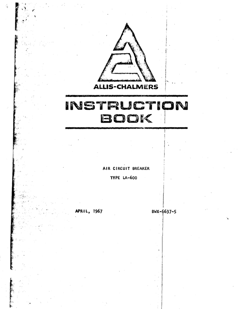
Allis-Chalmers LA-600 User manual

Allis-Chalmers

Allis-Chalmers LA-600 User manual

Allis-Chalmers LA-600 User manual

Allis-Chalmers

Allis-Chalmers LA-600 User manual
Allis-Chalmers FB-500A-FC-750A User manual

Allis-Chalmers

Allis-Chalmers FB-500A-FC-750A User manual

Allis-Chalmers LA-600 User manual

Allis-Chalmers

Allis-Chalmers LA-600 User manual

Allis-Chalmers LA-1600 User manual

Allis-Chalmers

Allis-Chalmers LA-1600 User manual

Allis-Chalmers LA-25 Installation manual

Allis-Chalmers

Allis-Chalmers LA-25 Installation manual

Allis-Chalmers LA 3000 User manual

Allis-Chalmers

Allis-Chalmers LA 3000 User manual

Allis-Chalmers MA-75 User manual

Allis-Chalmers

Allis-Chalmers MA-75 User manual
Popular Circuit Breaker manuals by other brands

Schrack MC2-160-XKC installation instructions

Schrack

Schrack MC2-160-XKC installation instructions

Eaton PKE12 Series manual

Eaton

Eaton PKE12 Series manual

CHINT NXM Series User instructions

CHINT

CHINT NXM Series User instructions

Camtec ESB101 manual

Camtec

Camtec ESB101 manual

Siemens 3VA10-ED Series operating instructions

Siemens

Siemens 3VA10-ED Series operating instructions

Eaton DDC-125/2 Instruction leaflet

Eaton

Eaton DDC-125/2 Instruction leaflet

OEZ OLFI Instructions for use

OEZ

OEZ OLFI Instructions for use

Westinghouse DE-ION DH Series Instruction book

Westinghouse

Westinghouse DE-ION DH Series Instruction book

Eaton Moeller DIL-SWD-32-001 Instruction leaflet

Eaton

Eaton Moeller DIL-SWD-32-001 Instruction leaflet

LEGRAND DPX instruction sheet

LEGRAND

LEGRAND DPX instruction sheet

Siemens AFCI Instructions for installation

Siemens

Siemens AFCI Instructions for installation

Solar Stik BOS 2000-120 manual

Solar Stik

Solar Stik BOS 2000-120 manual

Siemens PCTL83 installation instructions

Siemens

Siemens PCTL83 installation instructions

Doepke DRCBO 2 Series User information

Doepke

Doepke DRCBO 2 Series User information

ABB K-Line Plus KP-8 Installation & maintenance instructions

ABB

ABB K-Line Plus KP-8 Installation & maintenance instructions

Allen-Bradley 140G Series Adjustment instructions

Allen-Bradley

Allen-Bradley 140G Series Adjustment instructions

hager HY 801, HY 802 User instructions

hager

hager HY 801, HY 802 User instructions

GenInterlock SIE-P2 instructions

GenInterlock

GenInterlock SIE-P2 instructions

manuals.online logo
manuals.online logoBrands
  • About & Mission
  • Contact us
  • Privacy Policy
  • Terms and Conditions

Copyright 2025 Manuals.Online. All Rights Reserved.