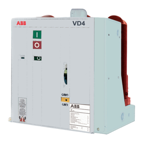
ABB VD4 Series Installation and operating instructions

—
VD4-36kV vacuum CB cradle solutions
for retrofitting SF6 gas CB HPA36
Addendum to VD4 installation,
operation and maintenance manual
—
DISTRIBUTION SOLUTIONS
VD4-36kV vacuum CB cradle solutions for
retrofitting SF6 gas CB HPA36
Addendum to VD4 installation, operation and
maintenance manual 36kV Up to 2000A...31.5kA

—
The VD4-36kV cradle retrofit
solution makes the use of fixed
VD4 type of circuit breaker.
For this reason, most of the
information contained in the
VD4 instruction manual is also
effective for this retrofit solution.

3
—
Table of contents
04 For your safety
04 Introduction
04 Environmental protection program
05 Applicability of VD4 instructions
manual to VD4-36kV cradle retrofit solution
06 Specific VD4-36kV cradle retrofit
instructions
06 Packing & transport
06 Handling
07 Handling with slings
08 Handling with trolley
09-10 Description
11-12 Instruction for VD4 CB operations
13-15 Installation
16 Putting into service
17-18 Periodic checking
19 Maintenance
19 Electrical diagram
20 Spare parts
21-22 Overall dimensions and ratings

4VD4-36KV CRADLE RETROFIT SOLUTION SERVICE INSTRUCTION MANUAL
—
For your safety
• Make sure that the installation room (spaces,
divisions and ambient) is suitable for the
electrical apparatus
• Check that all the installation, putting into
service and maintenance operations are
carried out by qualified personnel with
suitable knowledge of the apparatus
• Make sure that the standard and legal
prescriptions are complied with during
installation, putting into service and
maintenance, so that installations according
to the rules of good working practice and
safety in the workplace are constructed
• Strictly follow the information given in this
instruction manual
• Check that the rated performance of the
apparatus is not exceeded during service
• Check that the personnel operating the
apparatus have this instruction manual to
hand as well as the necessary information for
correct intervention
• Pay special attention to the danger notes
indicated in the manual by the following
symbol:
Responsible behavior safeguards
your own and others’ safety!
For any requests, please contact the
ABB Assistance Service.
I. Introduction
This publication contains the information needed
to install medium voltage VD4-36kV cradle
retrofit solution solution and put them into
service.
The installation of cradle retrofit solutions
require modification in existing VHA 36
switchgear panel.
However, this apparatus allows further
technical - construction modifications (at the
customer’s request) to adapt to special
installations.
Consequently, the information given below may
sometimes not contain instructions concerning
special configurations. Apart from this manual, it
is therefore always necessary to consult the latest
technical documentation (electric circuit and
wiring diagrams, assembly and installation
drawings, any protection co-ordination studies,
etc.), especially regarding any variants requested
in relation to the standardized configurations.
Only use original spare parts for maintenance
operations. For further information, please also
see the technical catalogue of the circuit-breaker
and the spare parts
All the installation, putting into
service, running and maintenance
operations must be carried out by
skilled personnel with in-depth
knowledge of the apparatus.
II. Environmental protection
program
The VD4-36kV cradle retrofit solutions are
manufactured in accordance with the ISO 14000
standards (Guidelines for environmental
management).
The production processes are carried out in
compliance with the standards for environmental
protection in terms of reduction in energy
consumption as well as in raw materials and
production of waste materials.
All this is thanks to the environmental
management system of the medium voltage
apparatus manufacturing facility.
5
The VD4-36kV cradle retrofit solution makes use
of fixed version of VD4 type circuit breaker.
For this reason, most of the information
contained in the VD4 instruction manual
(1VYN400990-051 Rev 00) are effective also for
this retrofit solution.
Following versions of fixed VD4 circuit breakers
are used with the VD4-36kV cradle retrofit
solution.
CB Type Ur (kV) Ir (A) Isc (kA)
VD4
36.12.32
36 1250 31.5
VD4
36.20.32
36 2000 31.5
In details, with reference to the VD4 installation
manual, the following sections are in common for
specifically VD4 circuit breakers .
Please refer to the VD4 instruction manual:
• Section 3 - Storage
• Section 5 - Description:
- Section 5.1 - General
- Section 5.2 - Reference standard
- Section 5.3 - EL operating mechanism
- Section 5.4 - Fixed circuit breaker
- Section 5.4.1 - General characteristics of
fixed circuit-breakers(36Kv)
- Section 5.4.2 - Type of circuit breakers
available in fixed version
- Section 5.6 - Characteristics of the
electrical accessories
(excluding locking magnet on truck-RL2)
• Section 6 - Instructions for operating the
circuit breaker
• Section 7 - Installation:
- 7.1 - General
- 7.2 - Installation and operating conditions
- 7.3 - Preliminary operations
• Section 9 - Maintenance
• Section 10 - Application of the X-ray emission
standards
• Section 11 - Spare parts & accessories
• Section 13 - Overall dimensions -Fixed circuit
breaker
• Section 14 -Product quality and
environmental protection
The specific information regarding the VD4-36kV
cradle retrofit solution is explained in this
addendum.
—
Applicability of VD4 instructions manual
to VD4-36kV cradle retrofit solution

6VD4-36KV CRADLE RETROFIT SOLUTION SERVICE INSTRUCTION MANUAL
—
Specific VD4-36kV cradle retrofit
instructions
Packing and transport
The medium voltage VD4-36kV cradle retrofit
solution CBs are delivered firmly screwed to the
floor of their containers or crates and must
always be transported or stored in an upright
position.
The circuit breaker is shipped in open condition
and with closing spring discharged. Each piece of
apparatus is protected by plastic cover to prevent
any infiltration of water during the loading and
unloading stages and to keep the dust off during
storages.
Checking on receipt
Before carrying out any operation,
always make sure that the operating
mechanism spring is discharged, and
that the apparatus is in the open
position.
On receipt, check the status of apparatus,
integrity of the packing and correspondence with
name plate data (see figure 6.1) with what is
specified in the order confirmation and in the
accompanying shipping note.
Also make sure that all the materials described in
the shipping notes are including in the supply.
Should any damage or irregularity be noted in the
supply on packing, notify ABB (directly or through
the agent or supplier) as soon as possible and
in any case within five days of receipt.
The cradle retrofit solution is only supplied with
the accessories specified at time of ordering and
validated in the order confirmation sent by ABB.
The accompanying documents inserted in the
shipping packing are:
• Instruction manual (this document)
• Test certification for CB
• Identification label
• Copy of the shipping documents
• Electric wiring diagram
Other documents which are sent prior to
shipment of the apparatus are:
• Order confirmation
• Original shipping advice note
• Any drawing or documents referring to
specific configurations / conditions
Note: Always take photographs to document any
major damage.
Handling
Before carrying out any operation, always check
that the operating mechanism springs are
discharged and that the apparatus is in the open
position.
Always take great care during handling not to
stress the insulating parts like epoxy pole
housing of the breaker and the terminals
of circuit breaker.
—
Fig 6.1
-

7
Handling with slings:
- To lift and handle the circuit-breaker, use the
hooks (figure 7.1 & 7.2).
- Put the hooks in the holes prepared in
the lifting bracket fixed on circuit-breaker
frame and lift with appropriate capacity
overhead crane.
Always take great care during handling not to
stress the insulating parts and the circuit-breaker
terminals.
—
Fig 7.1
—
Fig 7.2
—
Fig 7.3
In any case, it is always advisable to carry out
lifting using the supports (figure 7.4,& 8.1) in
position C.
—
Fig 7.4
While using forklift :
The apparatus must not be handled
by inserting forks of the truck
directly under the apparatus itself.
Should it be necessary to use this
method, place the circuit-breaker on
a sturdy supporting surface
(Wooden pallet) (see figure 7.3).

8VD4-36KV CRADLE RETROFIT SOLUTION SERVICE INSTRUCTION MANUAL
—
Specific VD4-36kV cradle retrofit
instructions
VD4-36kV cradle Position of hole for hook
1250A C
2000A C
Handling with trolley:
- To lift and handle the circuit-breaker, circuit
breaker lifting trolley can also be used as
shown in figure 8.2.
In order to lift the circuit breaker by trolley, circuit
breaker needs to be placed on firm platform of
wooden / plastic pallet of height @ 100mm.
The trolley is then positioned near the pallet & the
resting platform of trolley is brought to the level
@ 5mm lower to the pallet surface on which CB is
placed. Lock the front wheels by pressing locking
bracket provided on swivel roller wheel.
Circuit breaker is pulled on the resting platform
of the trolley. With the help of rotating handle of
trolley, the resting platform can be moved up &
down depending on the direction of rotation of
the handle.
—
Fig 8.1
In order to insert circuit breaker into the VHA 36
panel, position the trolley in front of the panel &
lift the CB resting surface of trolley up to the level
of surface of the guiderails in the panel. Move the
trolley closer to panel with both side wheel of the
CB common truck approximately equally spaced
from both guide rails. Lock the front wheels of
trolley by pressing locking bracket provided on
swivel roller wheel. Push the CB inside the panel
by taking care that front wheels of common
trucks enters in the guiderails.
Once the CB is entirely inserted in panel, unlock
the swivel roller wheel of the trolley & move the
trolley back away from panel & lower the CB
resting face & move away trolley from panel.
In order to place CB precisely in TEST position
inside panel, lock the left & right latches of the
common truck in vertical slots of left & right
guide rail so that CB can be locked in TEST
position.
—
Fig 8.2

9
—
Description
General
The VD4-36kV cradle retrofit solution circuit
breakers are pieces of apparatus with vacuum
technology for indoor installation. For the
electrical performances, please refer to the
corresponding technical catalogue code
1VCP000307.
For special installation requirements, please
contact ABB.
The following versions are available:
- Withdrawable CB for VHA 36 switchgear.
Ratings:
36kV 1250A 31.5kA
36kV 2000A 31.5kA
Reference standards
The VD4-36kV cradle retrofit solutions confirms
to the IEC 62271-100 standards.
EL operating mechanism
The VD4-36kV cradle retrofit solution circuit
breakers are equipped with modular EL3 type
spring operating mechanisms for short- circuit
current upto 31.5kA.
Withdrawable version
The VD4-36kV cradle retrofit solution circuit
breakers are equipped with common truck
assembly which makes it possible to make the
circuit breakers withdrawable version.
The VD4-36kV cradle retrofit solution is
specifically used for retrofitting SF6 gas circuit
breakers HPA36 in ABB make VHA36 panels.
The circuit breaker is having three pole
assemblies which are firmly mounted on steel
sheet frame. The contact arms along with the
tulip contacts are mounted on fixed pole
terminals. The steel frame assembly is fixed on
the common truck which is used to move the
circuit breaker from TEST to SERVICE position &
vice versa on guide rails provided on panel side.
The CB is delivered with control cable with
58 core cables and plug in 64 pin contacts for the
control circuit.
Earthed contact which is fitted on the left side of
truck frame automatically connects to fixed earth
slide provided on metal guide rails when CB is
inserted in guide rails.
1. Common truck
2. CB frame
3. Front wheel of common truck
4. LHS & RHS shutter lifting bracket
5. CB pole assembly
6. Top contact arm assembly
7. Bottom contact arm assembly
8. Top tulip assembly
9. Bottom tulip assembly
10. Cable stem
—
Fig 9.1
10
1
6
7
4
3
4
3
9
5
8
—
Fig 9.2
8
5
9
2

10 VD4-36KV CRADLE RETROFIT SOLUTION SERVICE INSTRUCTION MANUAL
1. Front cover
2. Opening & closing push buttons
3. Indication for circuit-breaker
OPEN / CLOSE
4. Indication for closing spring
charged / discharged
5. Operation counter
6. Lever for manually charging the
closing spring
7. Rating plate
8. Earthing contact
9. Common truck
10. Cable stem
11. Coil support
12. Locking magnet (-RL1) -
on request
13. Auxiliary contacts
14. Motor for spring charging
—
Description
—
Fig 10.1
10
2
3
6
7
8
1
2
4
5
9
—
Fig 10.2
13
14
12
11

11
Safety indications
All VD4 circuit-breakers guarantee a minimum
IP2X degree of protection when installed in
switchgear.
The operator is fully guaranteed against
accidental contact with moving parts under these
conditions.
Should mechanical operations be carried out on
the circuit-breaker outside the switchgear, take
great care of the moving parts.
The CB is provided with an interlocking
mechanism.
The interlocking device prevents closed CB from
being transferred to the connected or isolated
position, and against closing of CB during its
movement in the cubicle.
If the operations are prevented, do not force the
mechanical interlocks and check that the
operating sequence is correct.
Racking the circuit-breaker in and out of the
switchgear must be done properly to avoid
shocks, which may deform the mechanical
interlocks.
Switching and signaling parts
(figure 11.1)
Legends of figure 11.1
1 Front cover
2 Opening push button
3 Closing push button
4 Indication for circuit-breaker OPEN / CLOSE
5 Indication for closing spring charged /
discharged
6 Operation counter
7 Lever for manually charging the closing spring
8 Rating plate
9 Earthing contact
10 Cable stem
Circuit-breaker closing and
opening operations
Circuit-breaker operation can be either manual or
electrical (Figure 11.1).
a) Manual closing spring charging for VD4
circuit- breakers in earthed-test position
Repeatedly activate the charging lever (7)
(maximum rotation angle of the lever: about
90°) until the yellow indicator (5) appears.
The maximum forces which can normally be
applied to the lever are <250 N for EL3
operating mechanism.
b) Electrical spring charging operation
On request, the circuit-breaker can be fitted
with the following accessories for electrical
operation:
• Geared motor for automatic closing spring
charging
• Shunt closing release
• Shunt opening release
—
Instructions for VD4 CB operations
—
Fig 11.1 - VD4 basic version
10
2
4
7
8
9
1
3
5
6

12 VD4-36KV CRADLE RETROFIT SOLUTION SERVICE INSTRUCTION MANUAL
—
Instructions for VD4 CB operations
The geared motor automatically recharges the
spring after each closing operation until the
yellow indicator (5) appears. If the power is
cut off during charging, the geared motor
stops and automatically starts recharging the
springs again when the power returns.
In any case, it is always possible to complete
the charging operation manually.
c) Circuit-breaker closing
The operation can only be carried out
with the closing spring completely charged.
For manual closing, press the push button
(3 - figure 11.1)
When there is a shunt closing release, the
operation can also be carried out remotely by
means of a special control circuit.
Closing having taken place is indicated by the
signaling device (4 - figure 11.1)
d) Circuit-breaker opening
For manual opening, press the push button
(2 - figure 11.1). When there is a shunt opening
release, the operation can also be carried out
remotely by means of a special control circuit.
Opening having taken place is indicated by the
signaling device (4 - figure 11.1)

13
Preliminary operations
• Collect all auxiliary material required for
installation of the cradle retrofit solution
• Clean the insulating bushings on panel side
with clean dry cloths
CAUTION
Use proper personal protective
equipment like hand gloves, helmets
etc. while handling switchgears &
making cable connections.
NOTE
When carrying out installation work, the
regulations in the country of installation must
be strictly complied with.
Disconnect power, then earth and short circuit
connection before proceeding to work on the
switchgear.
Installation of VD4-36kV cradle
retrofit solution in VHA36
switchgear
The installation of VD4-36kV cradle retrofit
solution VCB in existing switchgear type VHA 36
requires modifications in existing switchgear
panel. Refer below steps for installation of
VD4-36kV cradle solution.
1. Remove following components from existing
VHA36 panel (refer fig 14.1, 14.2, 14.3, 14.4)
• SF6 circuit breaker HPA36
• CB compartment door (top) fixed with
shock absorber
• CB compartment main door
• Bottom front door
• Rear sheet of CB compartment
• Racking mechanism assembly
• LHS and RHS guide rails in CB compartment
• 24 pin socket and TEST/SERVICE limit
switches along with wiring from terminal
blocks in panel
• Emergency trip assembly and earth guide
2. Fix/mount following new components in
existing VHA36 panel (refer fig 15.1, 15.2, 15.3)
• Bottom plate assembly after preparing it
along with guide rails, guide brackets and
earth guides
• Rear bottom plate of CB compartment
• Top cover (upper door) assembly above CB
compartment main door
• CB compartment main door suitable for
cradle retrofit solution VCB
• Bottom front door
• 64 pin socket along with wiring up to
terminal blocks in panel
Once the preparation of panel assembly is
completed by mounting new bottom plate with
guide rail & new front door, withdrawable
VD4-36kV cradle retrofit solution VCB can be
inserted in the panel with the help of CB handling
trolley (refer fig 8.2 - Handling with trolley).
Circuit-breaker racking-in/-out must be carried
out properly to avoid shocks which may deform
the mechanical interlocks and the limit switches.
If operations are prevented or difficult, do not
force them and check that the operating
sequence is correct.
CAUTION
During installation of VD4-36kV
cradle solution with withdrawable
VCB, ensure that power supply to the
panel is completely switched off and
there is no residual charge present
on cubicle contact by use of proper
earthing.
Wiring of auxiliary circuit
The auxiliary circuits of the withdrawable
circuit- breaker are fully cabled from the factory
up to male connector.
For the external connections, please refer to the
electric diagram of the enclosure or of the
switchgear. The female connector in the existing
panel must be replaced with the corresponding
female connector suitable for male connector of
CB & cabling of the panel to be done up to the
female connector during installation.
—
Installation

14 VD4-36KV CRADLE RETROFIT SOLUTION SERVICE INSTRUCTION MANUAL
—
Installation
Components to be removed from
existing VHA 36 Panel
—
Fig 14.1
2
—
Fig 14.2
Legends of fig 14.1 and 14.2:
1 SF6 circuit breaker HPA36
2 CB compartment door (top)
3 CB compartment main door
4 Bottom front door
3
4
—
Fig 14.4
1
2
3
1 24 pin socket
2 Emergency trip assembly
3 Earth guide assembly
2
1
3
4
1
3
3
2
—
Fig 14.3
1 CB compartment rear sheet
2 Racking mechanism assembly
3 LHS & RHS guide rails

15
—
Installation
New components to be fixed/
mounted on existing VHA 36 Panel
—
Fig 15.1
1 Bottom plate assembly
2 Earth guide
3 LHS & RHS guide rails
4 Rear bottom plate
—
Fig 15.2
1 CB compartment top cover
(upper door) assembly
2 VD4-36kV circuit breaker
3 CB compartment main door
4 Bottom front door
4
1
2
3
1
2
3
4
—
Fig 15.3
—
Fig 15.4 - ABB VHA36 panels retrofitted with VD4-36kV cradle solution

16 VD4-36KV CRADLE RETROFIT SOLUTION SERVICE INSTRUCTION MANUAL
—
Putting into service
General procedures
Wiring of auxiliary circuit
The auxiliary circuits of the withdrawable circuit- breaker
are fully cabled from the factory up to male connector.
For the external connections, please refer to the electric
diagram of the enclosure or of the switchgear. The female
connector in the existing panel must be replaced with the
corresponding female connector suitable for male
connector of CB & cabling of the panel to be done up to the
female connector during installation.
Before putting the circuit-breaker into service, carry out
the following operations:
• Check the tightness of the power connections on the
circuit-breaker terminals
• Establish the setting of the direct solid-state overcurrent
release (if provided)
• Check that the value of the supply voltage for the
auxiliary circuits is within 85% and 110% of the rated
voltage of the electrical devices
• Check that no foreign body, such as bit of packaging, has
got into the moving parts
• Check that air circulation at the circuit-breaker
installation site is adequate so that there is no danger of
overheating
• Carry out the checks indicated in table 2.1 (see page 17)
CAUTION
During installation of VD4 CB first time with
existing panel, before inserting VD4 CB inside
cubicle ensure that power supply to the panel is
completely switched off and there is no residual
charge present on cubicle contact by use of
proper earthing
CAUTION
All the operations regarding putting into
service must be carried out by ABB personnel or
personnel who are suitably qualified and have
in- depth knowledge of the apparatus and
installation. If the operations are prevented, do
not force the mechanical interlocks, but check
that the operation sequence is correct
The racking-in/-out operations must always be carried out
with the circuit-breaker open.
While putting into service for the first time, before
connecting secondary plug with panel socket, it is advisable
to charge the circuit- breaker operating mechanisms
manually so as not to overload the auxiliary power supply
circuit.
When the CB is inserted in the in the guide fixed on panel
side, check the following:
• Free movement of breaker from test to service position
and vice versa
• Proper engagement of secondary plug and socket
• Proper functioning of various interlocks
• Proper engagement of earthing contact
• Proper engagement of VCB tulip contact with cubicle
pin contact

17
—
Periodic checking
CAUTION
Before carrying out any operation, make sure
that the operating mechanism springs are
discharged, and that the apparatus is in the
open position.
General
During normal service, the circuit-breakers are
maintenance free.
The frequency and sort of inspections basically depend on
the service conditions. Various factors must be considered:
frequency of operations, interrupted current values, relative
power factor and the installation ambient.
The following paragraph gives the checking program table,
showing the relevant time intervals.
As far as the time interval between these operations is
concerned, it is advisable to comply with the specifications
given in the table, at least during the first check. On the
basis of the results obtained during the periodic
inspections, set the optimal time limits for carrying out the
operations listed in table 2.2 (see page 16).
Table 2.1
Subject of the
inspection
Procedure Positive check
1Insulation
resistance
Medium voltage circuits
With a 2500 V megger, measure the insulation resistance between phases
and exposed conductive part of the circuit.
Auxiliary circuits
With a 500 V megger (installed equipment permitting) measure the
insulation resistance between the auxiliary circuits and the exposed
conductive part.
The insulation resistance should be a few MΩ
and, in any case, constant over time.
The insulation resistance should be at least 50
MΩ and, in any case, constant over time.
2Auxiliary
circuits
Check that the connections to the control circuit are correct; proceed with
relative supply.
Normal switching and signaling.
3Manual
operating
mechanism
Carry out a few closing and opening operations. N.B. Supply the u/v
release and the locking magnet on the operating mechanism at the relative
rated voltage
The operations and relative signals occur
correctly.
4 Motor
operator*
Supply the geared motor for spring charging at the relative rated voltage.
Carry out a few closing and opening operations. N.B. Supply the
undervoltage release and the locking magnet on the operating mechanism
at the relative rated voltage. (if provided)
The springs are charged correctly. The signals are
correct.
The geared motor cuts off when the springs are
charged.
The geared motor recharges the springs after
each closing operation.
5Under voltage
release*
Supply the undervoltage release at the relative rated voltage and carry out
the circuit-breaker closing operation. Disconnect the power supply to the
release.
The circuit-breaker closes correctly. The signals
are correct.
The circuit-breaker opens. The signal changes
over.
6Shunt opening
release and
additional
shunt opening
release*
Close the circuit-breaker.
Supply the shunt opening release at the relative rated voltage.
The circuit-breaker opens correctly. The signals
are correct.
7Shunt closing
release*
Open the circuit-breaker. Supply the shunt closing release at the relative
rated voltage.
The circuit-breaker closes correctly. The signals
are correct.
8Key lock* Open the circuit-breaker Turn the key and remove it
Attempt the circuit-breaker closing operation
Insert the key again and turn it 90°
Carry out the closing operation
Neither manual nor electric closing takes place.
Both electric and manual closing take place
correctly; in this position the key cannot be
removed.
9Locking
electromagnet
(RL1)*
With the circuit-breaker open, springs charged and locking electromagnet
not supplied, attempt to close the circuit-breaker both manually and
electrically.
Closing is not possible.
10 Auxiliary
contacts in the
operating
mechanism
Insert the auxiliary contacts into suitable signaling circuits. Carry out a few
closing and opening operations.
Signals occur correctly.
11 Racking device
with lever on
the unit
With closed circuit-breaker try to operate the lever. The lever cannot be operated and the racking-out
are not possible.

18 VD4-36KV CRADLE RETROFIT SOLUTION SERVICE INSTRUCTION MANUAL
Table 2.2
Checking operation Time interval Criteria
1 Carry out five mechanical
opening/closing operations
1 year The circuit-breaker must operate normally without stopping in
intermediate positions.
2 Visual inspection of the poles
(parts in resin)
1 year or 5000 operations The parts in resin must be free of any accumulation of dust,
dirt, cracks, discharges or traces of surface discharges.
3 Visual inspection of the
operating mechanism and
transmission
1 year or 5000 operations The elements must be free of any deformation.
Screws, nuts, bolts, etc. must be tight.
4 Visual inspection of the
isolating contacts
5 years or 5000 operations The isolating contacts must be free of any deformation or
erosion.
Lubricate the contact elements with industrial Vaseline
grease.
5Measuring the insulation
resistance
5 years or 5000 operations See table 2 1. point 1
6Checking interlock operation 5 years The interlocks provided must operate correctly
—
Periodic checking

19
—
Maintenance must only be carried out by ABB personnel or in any case
by suitably qualified personnel who have in-depth knowledge of the
apparatus (IEC62271-1). Should the maintenance be carried out by
non-ABB personnel, they are responsible for the interventions.
Replacement of any parts not included in the “list of spare parts / accessories” must only be carried out
by ABB personnel.
In particular:
• Complete pole with bushings / connections
• Operating mechanism
• Closing spring unit
• Opening spring
• Spring charging geared motor with electrical signaling spring charged
• Epoxy bushing assembly
• Fixed contact
—
Maintenance
—
Electrical diagram
The standard VD4 circuit-breaker electric circuit diagram is as follows:
• VD4 electric diagram
Each circuit-breaker is always provided with the standard electric diagram or with a specific
diagram in the case of a circuit-breaker with non-standard cabling.
The standard VD4 circuit breaker electric diagram is as per drawing 1VYN300901-UJ
Wiring of auxiliary circuits
• The auxiliary circuits of the withdrawable circuit- breaker are fully cabled in the factory up to male
connector.
• For the external connections, please refer to the electric diagram of the enclosure or of the
switchgear. The Female connector in the old panel must be replaced with the corresponding female
connector suitable for male connector of CB & cabling of the panel to be done up to the female
connector during installation

20 VD4-36KV CRADLE RETROFIT SOLUTION SERVICE INSTRUCTION MANUAL
—
Spare parts
—
All assembly operations of spare
parts / accessories must be
carried out by ABB personnel or
by suitably qualified customer
personnel with in-depth
knowledge of the apparatus,
following the instructions
enclosed with the spare parts,
(IEC62271-1) and all the standards
aimed at carrying out these
interventions in safe conditions.
Should maintenance be carried
out by the customer’s personnel,
responsibility for the
interventions lies with the
customer. Before carrying out any
operation, always make sure that
the circuit-breaker is open, the
spring discharged and that it is
not energized (medium voltage
circuit and auxiliary circuits)
To order circuit-breaker spare parts / accessories,
refer to the ordering sales codes indicated in the
technical catalogue and always state the
following:
• Type of circuit-breaker
• Rated voltage of the circuit-breaker
• Rated normal current of the circuit-breaker
• Breaking capacity of the circuit-breaker
• Serial number of the circuit-breaker
• Rated voltage of any electrical spare parts
For availability and to order spare parts, please
contact our service office.
List of spare parts for breaker
• Shunt opening release
• Additional shunt opening release
• Shunt closing release
• Contact signaling protection circuit-breaker
of the geared motor open / closed
• Contact signaling closing spring charged /
discharged
• Circuit-breaker auxiliary contacts
• Locking electromagnet on the operating
mechanism
• Position contact of the withdrawable truck
• Contacts signaling connected / isolated
• Opening solenoid
• Charging motor
• Key lock in open position
• Protection for opening push button
• Protection for closing push button
• Set of six tulip contacts
• Open / closed signaling device
• Set of six fixed contacts
• Racking handle
Other manuals for VD4 Series
11
Table of contents
Other ABB Circuit Breaker manuals

ABB
ABB SACE Tmax XT User manual

ABB
ABB Record Plus FB100 User manual

ABB
ABB SACE Emax 2 User manual

ABB
ABB SACE Emax 2 User manual

ABB
ABB AC500 V3 User manual

ABB
ABB SF6 LTB 245E1 BLG 1002A User manual

ABB
ABB SACE Emax Guide

ABB
ABB SACE Emax 2 E2.2 User manual

ABB
ABB SACE Emax 2 User manual

ABB
ABB OHB Installation and user guide
Popular Circuit Breaker manuals by other brands

Utility Relay Company
Utility Relay Company AC-PRO instructions

Perun
Perun AB User and installation manual

FEDERAL PACIFIC
FEDERAL PACIFIC FUSEMATIC FP25-600 instruction manual

Siemens
Siemens WL Series operating instructions

Allen-Bradley
Allen-Bradley 140G-K-EA1R1A Installation

GenInterlock
GenInterlock SD-H200A quick start guide