Allis-Chalmers LA-25 Installation manual
/
'
*
\
j
£
t
;
v
•
v
•
t
*
:
L
'
i
;
;
>
•
:
?
i
tire
Installation
,
Care
and
Operation
of
Circuit
Breakers
and
Accessories
%
•
V
•
t
;
?
•
•
'
!
V
;
.
.
*
*
•
i
%
:
•
v
:
*
v
.
;
•
-
-
V
-
;
*
*
/
;
.
/
.
•
*
V
'
'
:
wZr
'
:
v
r
V
‘
;
*
/
•
’
•
/
'
i
.
:
0
)
I
•
*
--
V
-
:
.
:
•
:
•
:
!
V
-
-
/
•
>
/
*
:
:
t
:
•
.
.
•
:
•
:
•
*
-
L
•
/
•
•
:
•
:
•
J
r
”
•
•
•
'
.
r
;
•
'
"
‘
V
:
V
•
r
.
h
•
•
’
/
•
c
L
?
‘
'
/
.
r
-
•
.
^
-
•
/
•
%
*
.
.
•
TUxEi
)
LA
-
25
AIR
CIR
CTO
BREAKER
BOOK
BWX
-
6426
•
•
r
r
‘
.
:
>
:
•
:
/
.
r
;
:
•••
:
•
<
'
-
V
•
;
•
•
•
•
'
M
.
'
S
'
.
.
•
itv
S
•
:
:
f
•
•
*
i
H
•
•
:
•
.
f
:
'
.
•
VB
••
*
:
>
V
•
V
.
*
1
*
'
•
'
J
v
'
S
These
instructions
ahe
not
intended
to
cover
all
details
or
variations
that
may
he
encountered
in
connection
;
with
the
installation
,
operation
,
and
maintenance
of
this
equipment
.
Should
additional
information
he
desired
contact
the
Allis
-
Chalmers
Mfg
.
Company
.
/
AIIIS
CHAIMERS
MFG
.
CO
.
BOSTON
WORKS
.
BOSTON
.
MASS
.
r
r
*
.
Courtesy of NationalSwitchgear.com

'
4
ALLIS
-
CHALMERS
^
MANUFACTURING
COMPANY
:
INDEX
TO
INSTRUCTION
BOOK
COVERING
TYPE
LA
-
25
AIR
CIRCUIT
BREAKER
Page
No
Contents
Part
I
.
General
Information
A
.
Introduction
B
.
Warranty
C
.
Receiving
'
and
Inspection
for
Damage
.
D
Storage
,
Part
II
,
Installation
and
Operation
1
1
1
1
A
.
Mounting
B
.
'
Inspection
C
.
Operating
Mechanism
Check
D
.
Trip
Units
and
Accessory
Devices
E
.
Pantograph
and
Trip
Interlock
Adjustment
F
.
Energizing
the
Breaker
Part
III
.
Description
and
Function
of
Parts
2
2
3
3
3
4
4
k
,
Operating
Mechanism
B
.
Contacts
Method
of
^
-
Are
Interruption
D
,
Relays
K
.
Trip
Units
and
Accessory
Devices
Part
IV
.
Maintenance
.
Adjustment
and
Replacement
l
C
6
7
7
A
«
General
B
.
Periodic
Inspection
C
.
Maintenance
Check
D
.
Movable
Arcing
Contact
E
.
'
Stationary
Arcing
Contact
F
.
Movable
Main
Contact
G
.
Stationary
Main
Contact
H
.
Trip
Units
and
Accessory
Devices
(
Manual
)
(
Electrical
)
7
7
.
List
9
9
10
10
10
10
I
.
Operating
Mechanism
J
.
Operating
Mechanism
K
.
Closing
Coil
11
11
'
a
.
)
-
f
V
;
BWX
-
6426
Courtesy of NationalSwitchgear.com
•
r
ALLIS
-
CHALMERS
<
$
>
MANUFACTURING
COMPAiV
Contents
(
Cont
Td
.
)
Page
No
.
Part
V
.
Protective
Devices
A
.
Series
Overcurrent
Trip
Device
Assembly
Adjustment
and
Calibration
Inspection
and
Adjustment
Maintenance
and
Replacement
B
.
Thermal
Magnetic
Overcurrent
Trip
Device
Assembly
-
Inspection
and
Adjustment
Maintenance
and
Replacement
C
.
Overcurrent
Trip
Flag
Indicator
and
Reset
'
Part
VI
.
Accessory
Attachments
11
13
13
U
15
16
16
16
A
.
Shunt
Trip
Attachment
B
.
.
Auxiliary
Switch
Attachment
C
.
.
Bell
Alarm
Switch
Attachment
D
.
Mechanical
Overcurrent
Lockout
Attachment
17
17
17
m
:
<
,
BWZ
-
6426
Courtesy of NationalSwitchgear.com
ALLIS
-
CHALMERS
<
$
>
MANUFACTURING
COMPANY
m
•
*
i
LIST
OF
ILLUSTRATIONS
COVERING
ALLIS
-
CHALMERS
TIPS
LA
-
25
LOW
VOLTAGE
AIR
CIRCUIT
BREAKER
vAND
AUXILIARY
EQUIPMENT
Description
Figure
Electrically
Operated
Breaker
Manually
Operated
Breaker
1
2
3
Operating
Mechanism
(
Schematic
)
4
5
6
Wiring
Diagrams
Auxiliary
Switch
Secondary
Disconnect
Closing
Solenoid
Limit
Switch
Shunt
Trip
Device
Series
Trip
Device
Thermal
Trip
Device
Indicator
Flag
,
Mechanical
Lockout
,
Bell
Alarm
Switch
,
and
Reset
Button
'
tor
Overcurrent
Trip
Devices
Series
Trip
Curves
(
Dual
Magnetic
)
Series
Trip
Curves
(
Dual
Selective
)
Thermal
Trip
Curves
7
£
9
10
11
12
13
14
15
16
17
BWX
-
6426
Courtesy of NationalSwitchgear.com

/
*
ALUS
-
CHALMERS
<
^
>
MANUFACTURING
COMP
*
Y
!
CAUTIONS
TO
BE
OBSERVED
IN
THE
-
INSTALLATION
AND
OPERATION
OF
THE
LA
-
25
AIR
CIRCUIT
BREAKER
1
.
DO
NOT
ATTEMPT
TO
OPERATE
BREAKER
OR
INSERT
IN
CUBICLE
UNTIL
ALL
PACKING
TRACES
'
HAVE
BEEN
REMOVED
.
BREAKER
IS
SHIPPED
LOCKED
IN
CLOSED
POSITION
.
READ
INSTRUCTION
BOOK
BEFORE
MAKING
ANT
CHANGES
OR
ADJUSTMENTS
ON
THE
BREAKER
.
...
'
2
.
DO
NOT
INTERCHANGE
PARTS
OF
TRIP
DEVICES
MAT
CHANGE
CALIBRATIONS
.
TO
DO
SO
3
.
4
.
ALWATS
OPERATE
MANUAL
CLOSING
HANDLE
QUICKLT
AND
DECISIVELT
-
TO
HESITATE
IN
MIP
-
STROKE
MAT
CAUSE
UNDUE
BURNING
OF
CONTACTS
.
CHECK
CURRENT
RATINGS
AND
SERIAL
NUMBERS
AGAINST
SINGLE
LINE
DIAGRAM
TO
ASSURE
THAT
BREAKERS
ARE
PRQPERLT
LOCATED
IN
SWITCHGEAR
AT
INSTALLATION
,
5
.
•
Y
/
BWI
-
64
^
6
>
k
Courtesy of NationalSwitchgear.com
INSTRUCTIONS
FOR
THE
INSTALLATION
AND
OPERATION
:
OF
ALLIS
-
CHALMERS
TYPE
LA
-
2
5
LOW
VOLTAGE
AIR
CIRCUIT
BREAKER
AND
AUXILIARY
EQUIPMENT
»
*
PART
I
GENERAL
INFORMATION
A
<
Introduction
.
The
type
LA
-
2
5
air
circuit
breaker
is
one
of
a
line
of
low
voltage
air
breakers
which
may
be
used
in
metal
enclosed
switchgear
,
on
open
type
switchboards
,
or
separate
-
ly
mounted
in
individual
housings
.
The
LA
-
25
air
circuit
breaker
has
an
interrupting
capacity
of
25
,
000
amperes
and
-
a
maximum
.
continuous
current
rating
of
600
amperes
at
600
volts
,
60
cycles
.
For
information
on
other
frequencies
,
the
factory
should
be
consulted
.
'
All
LA
-
25
breakers
are
completely
assembled
,
tested
,
and
calibrated
at
the
factory
in
a
vertical
position
and
must
be
so
installed
to
operate
properly
.
Customers
primary
connec
-
tions
should
be
adequately
braced
against
the
effects
of
short
circuit
currents
to
prevent
overstressing
the
breaker
terminals
.
B
.
Warranty
.
Allis
-
Chalmers
LA
-
25
air
circuit
breakers
are
'
warranted
to
be
-
free
of
defects
in
material
and
workmanship
for
a
period
of
one
year
after
delivery
to
the
original
'
purchaser
.
This
warranty
is
limited
to
the
furnishing
of
any
part
which
to
our
satisfaction
has
been
proven
defective
.
Allis
Chalmers
will
not
in
any
case
assume
responsibility
for
allied
equipment
of
any
kind
.
-
•
Receiving
and
Inspection
for
Damage
.
air
circuit
breaker
,
and
its
associated
apparatus
is
carefully
checked
,
inspected
,
and
packed
at
the
factory
by
workman
ex
-
perienced
in
the
proper
handling
of
electrical
equipment
.
Immediately
upon
receipt
of
this
equipment
,
carefully
remove
all
packing
trades
'
and
examine
parts
,
checking
them
against
the
packing
list
and
carefully
noting
any
damages
incurred
in
transit
.
If
’
such
is
disclosed
,
a
damage
claim
should
be
filed
at
once
with
Keep
Each
LA
-
25
G
the
transportation
company
and
Allis
-
Chalmers
notified
instruction
books
and
tags
with
the
breakers
.
;
D
.
Storage
.
When
breakers
are
not
to
be
put
into
immediate
use
,
they
should
be
carefully
wrapped
or
covered
to
provide
protection
from
plaster
or
concrete
dust
and
other
foreign
matter
.
Abrasive
dust
in
the
breaker
can
cause
excessive
friction
and
rapid
wear
.
Breakers
should
not
be
exposed
to
the
action
of
corrosive
gases
and
moisture
.
In
areas
of
high
humidi
-
ty
or
temperature
fluctuations
,
space
heaters
or
the
equivalent
9
\
>
i
BWX
-
6426
-
1
-
\
Courtesy of NationalSwitchgear.com

*
«
•.
A
*
•
*
should
be
provided
.
Circuit
breakers
should
be
handled
carefully
at
all
times
.
Shock
or
jars
in
rough
handling
can
cause
serious
damage
.
PART
II
INSTALLATION
AND
OPERATION
A
.
Mounting
.
The
LA
-
25
air
circuit
breaker
is
com
-
pletely
adjusted
,
test
.
ed
,
and
inspected
at
the
factory
before
shipment
and
no
additional
adjustment
should
be
necessary
when
installing
.
However
,
a
careful
check
should
be
,
made
to
be
certain
that
shipment
and
storage
has
not
resulted
in
damage
or
change
of
adjustment
{
See
next
paragraph
)
.
Circuit
breakers
should
be
installed
in
a
clean
,
dry
,
,
well
-
ventilated
place
in
which
the
atmosphere
is
free
from
destructive
acid
:
or
alkali
fumes
.
Mount
open
type
breakers
high
enough
to
prevent
injury
to
personnel
either
from
circuit
interruption
or
from
moving
parts
during
automatic
opening
of
the
breaker
.
Allow
sufficient
space
to
permit
access
for
cleaning
and
inspection
.
Also
allow
a
minimum
clearance
of
one
inch
to
an
.
insulating
barrier
above
the
breaker
to
prevent
damage
from
arcing
.
'
3
B
.
Inspection
.
Before
being
placed
in
service
the
breaker
should
be
given
a
final
inspection
to
be
certain
that
adjustments
and
connections
have
not
loosened
in
shipment
or
handling
.
Before
installing
breaker
,
make
certain
it
is
in
the
open
position
and
that
all
packing
traces
have
been
removed
(
breaker
is
shipped
blocked
in
the
closed
position
)
.
After
.
breaker
is
in
position
,
close
it
manually
to
check
-
proper
function
-
ing
of
the
mechanism
and
contacts
.
(
CAUTION
:
MAKE
SURE
CIRCUIT
IS
NOT
ENERGIZED
.
)
ing
resistance
until
fully
closed
and
latched
.
Breaker
should
operate
smoothly
with
increas
-
During
the
clos
-
ing
operation
,
observe
that
the
contacts
move
freely
without
interference
or
rubbing
between
movable
arcing
contacts
(
2
-
24
)
and
.
parts
of
the
arc
chute
(
2
-
21
)
.
Continue
to
close
and
observe
that
the
arcing
contacts
(
2
-
24
)
and
(
2
-
25
)
touch
before
the
main
(
2
-
34
)
and
(
2
-
33
)
.
Observe
that
when
main
~
;
contacts
touch
contacts
that
there
:
is
a
positive
wiping
action
which
will
produce
a
clear
-
ance
at
the
bottom
of
the
contacts
.
i
.
NOTE
:
-
Refer
to
Part
IV
,
Paragraph
C
,
Maintenance
Check
List
,
for
values
of
adjustments
and
settings
.
Check
to
be
sure
that
springs
are
not
solidly
compressed
.
Arcing
contact
springs
(
2
-
22
)
and
main
contact
finger
springs
(
2
-
32
)
and
(
2
-
37
)
in
particular
should
have
overtravel
to
insure
against
hard
closing
and
overstressing
of
the
breaker
parts
.
•
rv
.
A
m
-
2
-
BWX
-
6426
/
i
,
Courtesy of NationalSwitchgear.com

m
Observe
that
the
manual
operating
handle
{
2
-
13
)
returns
from
closed
to
neutral
positions
automatically
by
action
of
its
return
spring
(
2
-
9
)
.
rh
;
W
'
Next
open
breaker
'
by
means
of
manual
trip
button
(
2
-
1
)
on
front
of
breaker
.
The
toggle
'
linkage
(
2
-
53
)
will
collapse
,
the
contacts
will
move
to
the
open
position
freely
and
rapidly
/
and
the
closing
mechanism
will
reset
,
ready
for
the
next
operation
.
Operating
springs
(
2
-
4
)
assist
in
rapid
opening
of
the
contacts
and
actuate
the
resetting
of
the
closing
mechanism
,
C
.
Operating
Mechanism
Check
,
The
operating
mechanism
is
properly
adjusted
and
tested
at
the
factory
,
and
ordinarily
there
should
be
no
need
for
readjustment
in
the
field
.
If
,
for
some
reason
,
the
mechanism
fails
to
latch
in
the
closed
position
check
to
be
certain
that
all
trip
devices
are
reset
and
n
.
ot
interfering
with
the
trip
latch
(
2
-
43
)
.
'
The
trip
latch
'
should
be
free
to
.
return
to
'
its
latching
position
.
If
the
trip
latch
'
is
free
and
.
the
mechanism
still
fails
to
latch
,
check
to
be
certain
that
there
are
no
binds
or
interferences
in
the
mechanism
and
that
all
links
and
latches
are
fully
reset
.
If
breaker
is
still
unstable
,
the
trip
latch
reset
spring
(
2
-
42
.
)
may
be
adjusted
to
increase
its
reaction
against
the
latch
(
refer
to
Maintenance
Check
List
,
Part
IV
,
Section
C
)
.
However
,
before
changing
any
adjustments
be
certain
that
the
trip
latch
engagement
is
suffi
-
cient
,
as
outlined
in
the
maintenance
check
list
.
•
••
*
•
•
’
.
*
•
*
•
.
.
•
•
>
D
,
Trip
Units
and
Accessory
Devices
,
These
items
also
should
receive
a
thorough
check
prior
to
placing
breaker
in
service
to
be
certain
that
adjustments
are
proper
and
parts
are
not
damaged
.
Refer
to
Parts
V
and
VI
of
the
instruction
book
for
the
description
of
adjustments
and
functions
of
these
devices
.
r
f
:
E
,
Pantograph
and
Trip
Interlock
Adjustment
,
This
applies
only
to
cubicle
mounted
breakers
of
the
drawout
type
.
As
a
closed
breaker
is
racked
into
position
it
should
trip
shortly
after
it
passes
the
.
"
test
position
”
,
indicator
.
At
this
point
the
control
circuits
will
be
made
,
but
the
primary
connections
will
be
and
it
will
be
impossible
to
close
the
breaker
until
it
Continue
racking
'
open
reaches
the
"
operating
position
"
indicator
,
breaker
in
and
close
it
when
the
operating
position
is
reached
.
:
Closing
should
not
be
affected
by
the
interlock
mechanism
.
Then
as
the
closed
breaker
is
racked
out
towards
the
test
position
,
after
approximately
5
/
16
inches
travel
the
breaker
should
trip
.
disconnect
fingers
(
1
-
14
)
will
still
be
in
full
and
it
will
be
impossible
to
)
At
this
point
contact
with
the
stationary
stud
close
the
breaker
again
until
the
test
position
is
reached
,
the
mechanism
does
not
function
as
described
,
refer
to
the
cubicle
instruction
book
for
corrective
adjustments
.
>
If
%
.
/
•
r
*
BWX
-
6426
-
3
-
Courtesy of NationalSwitchgear.com
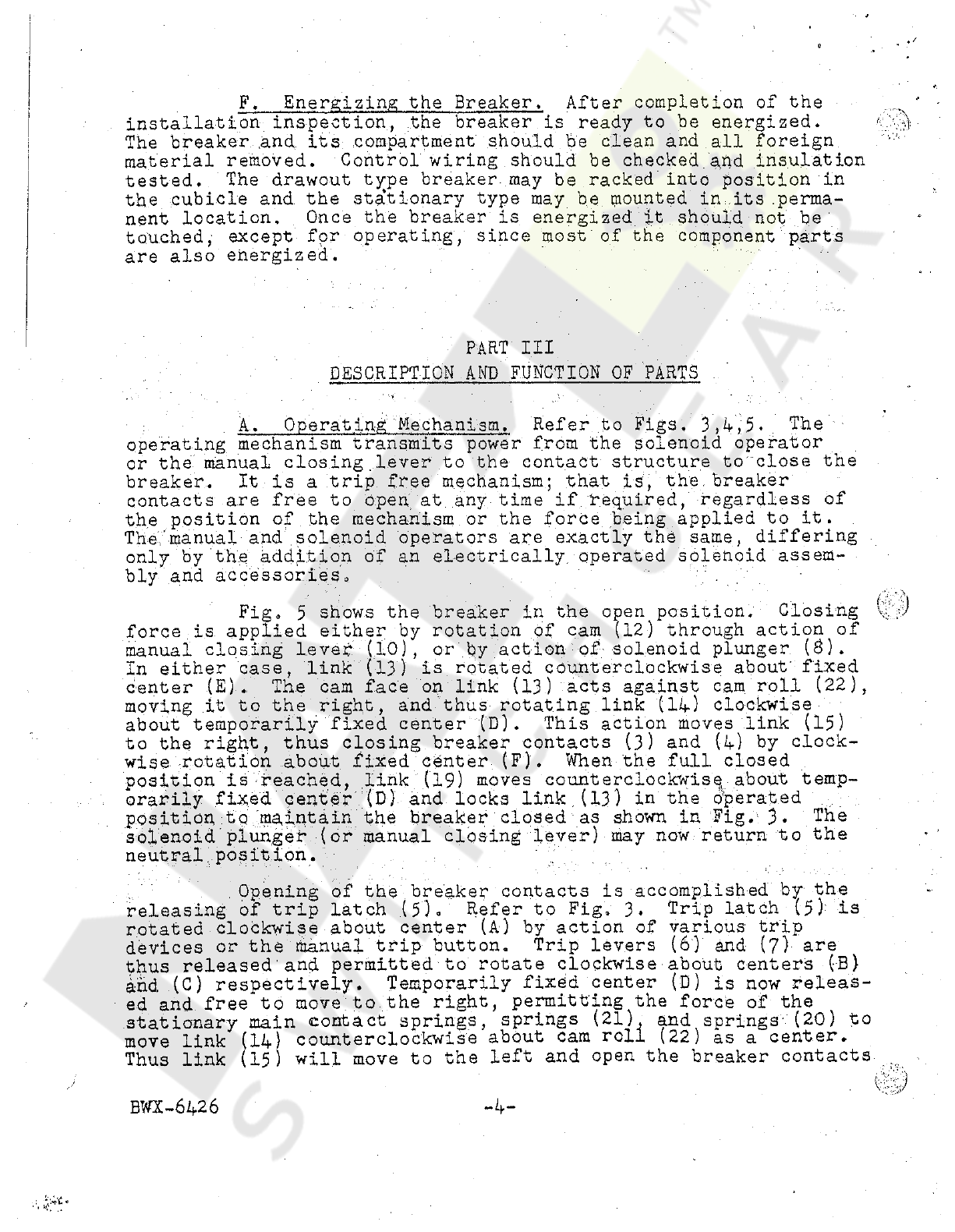
F
.
Energizing
the
Breaker
,
After
completion
of
the
installation
inspection
,
the
breaker
is
ready
to
be
energized
.
The
breaker
and
its
compartment
should
be
clean
and
all
foreign
material
removed
.
Control
wiring
should
be
checked
.
add
insulation
tested
.
The
drawout
t
^
pe
breaker
,
may
be
racked
into
position
in
the
cubicle
and
the
stationary
type
may
be
mounted
in
its
.
perma
-
nent
location
.
Once
the
breaker
is
energized
it
should
not
be
touched
,
except
for
operating
,
since
most
of
the
component
parts
are
also
energized
.
I
r
*
,
PART
III
DESCRIPTION
AND
FUNCTION
OF
PARTS
A
.
Operating
Mechanism
.
Refer
to
Figs
.
3
,
4
,
5
*
The
operating
mechanism
transmits
power
from
the
solenoid
operator
or
the
manual
closing
.
lever
to
the
contact
structure
to
close
the
breaker
.
It
is
a
trip
free
mechanism
;
that
is
,
the
,
breaker
contacts
are
free
to
open
at
.
any
time
if
required
,
regardless
of
the
position
of
the
mechanism
or
the
force
being
applied
to
it
.
The
manual
and
solenoid
operators
are
exactly
the
same
,
differing
only
by
the
addition
of
an
electrically
,
operated
solenoid
assem
-
bly
and
accessories
.
-
x
id
Fig
,
5
shows
the
breaker
in
the
open
position
.
Closing
force
is
applied
either
by
rotation
of
cam
(
12
)
through
action
of
manual
closing
lever
(
10
)
,
or
by
action
of
solenoid
plunger
(
$
)
.
In
either
case
,
link
(
13
)
is
rotated
counterclockwise
about
'
fixed
center
(
E
)
,
The
cam
face
on
link
(
13
)
acts
against
cam
roll
(
22
)
,
moving
it
to
the
right
,
and
thus
rotating
link
(
14
)
clockwise
about
temporarily
fixed
center
(
D
)
.
This
action
moves
link
(
15
)
to
the
right
,
thus
closing
breaker
contacts
(
3
)
and
(
4
)
by
clock
-
wise
rotation
about
fixed
center
(
F
)
.
When
the
full
closed
position
is
reached
,
link
(
19
)
moves
counterclockwise
about
temp
-
orarily
fixed
center
.
(
D
)
and
locks
link
(
13
)
in
the
operated
position
to
maintain
the
breaker
closed
as
shown
in
Fig
.
3
.
The
solenoid
plunger
(
or
manual
closing
lever
)
may
now
return
to
the
neutral
.
position
.
Opening
of
the
breaker
contacts
is
accomplished
by
the
releasing
of
trip
latch
(
5
)
.
Refer
to
Fig
,
3
.
Trip
latch
(
5
)
is
rotated
clockwise
about
center
(
A
)
by
action
of
various
trip
devices
or
the
manual
trip
button
.
Trip
levers
(
6
)
and
(
7
)
are
thus
released
'
and
permitted
to
rotate
clockwise
about
centers
(
B
)
and
(
C
)
respectively
.
Temporarily
fixed
center
(
D
)
is
now
releas
-
ed
and
free
to
move
,
to
the
right
,
permitting
the
force
of
the
stationary
main
contact
springs
,
springs
(
21
)
and
springs
'
(
20
)
to
link
(
14
)
counterclockwise
about
cam
roll
(
22
)
as
a
center
.
Thus
link
(
15
)
will
move
to
the
left
and
open
the
breaker
contacts
move
W
BWX
-
6426
-
4
-
v
.
;
c
*
Courtesy of NationalSwitchgear.com
(
3
)
and
-
.
(
4
)
.
v
.
•
&
•
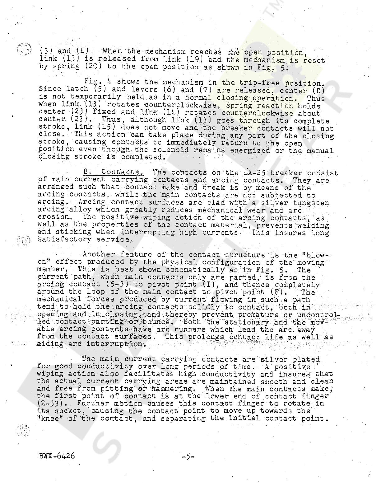
When
the
mechanism
reaches
the
open
position
,
link
(
13
)
is
released
from
link
(
19
)
and
the
mechanism
is
reset
by
spring
(
20
)
to
the
open
position
as
shown
in
Fig
.
5
*
Fi
go
1
+
shows
the
mechanism
in
the
trip
-
free
position
.
Since
latch
(
5
)
and
levers
(
6
)
and
(
7
)
are
released
,
center
(
D
)
is
not
temporarily
held
as
in
a
normal
closing
operation
.
.
Thus
when
link
(
13
)
rotates
counterclockwise
,
spring
reaction
holds
center
(
23
)
fixed
and
link
(
11
)
rotates
counterclockwise
about
center
(
23
)
.
Thus
,
although
link
(
13
)
goes
through
its
complete
stroke
,
link
(
15
)
does
not
move
and
the
breaker
contacts
will
not
close
.
This
action
can
take
place
during
any
part
of
the
closing
stroke
,
causing
contacts
to
immediately
return
to
the
open
position
even
though
.
the
solenoid
remains
energized
or
the
manual
closing
stroke
is
completed
.
B
,
Contacts
.
The
contacts
on
the
LA
-
25
breaker
consist
of
main
current
carrying
contacts
and
arcing
contacts
.
They
are
arranged
such
that
Contact
make
and
break
is
by
means
of
the
arcing
contacts
,
while
the
main
contacts
are
not
subjected
to
arcing
.
Arcing
contact
surfaces
are
clad
with
a
silver
tungsten
arcing
alloy
which
greatly
reduces
mechanical
wear
and
arc
:
erosion
.
The
positive
wiping
action
of
the
arcing
contacts
,
"
as
well
as
the
properties
of
the
contact
material
,
prevents
welding
and
sticking
when
interrupting
high
currents
,
This
insures
long
satisfactory
service
.
*
*
'
s
..
.
•
"
*
’
4
Another
feature
of
the
contact
structure
is
the
"
blow
-
on
"
effect
produced
by
the
physical
configuration
of
the
moving
member
.
This
is
best
shown
schematically
as
in
Fig
.
5
*
'
The
current
path
,
when
main
contacts
only
are
parted
,
is
from
the
arcing
contact
(
5
-
3
)
to
pivot
point
(
X
)
,
and
thence
completely
around
the
loop
of
the
main
contact
to
pivot point
(
Fj
.
The
mechanical
forces
produced
hy
current
flowing
in
such
.
a
path
tend
to
hold
the
arcing
contacts
solidly
in
contact
,
both
in
opening
-
and
.
in
.
closing
and
thereby
prevent
prernature
or
uhcontrol
.
.
led
contact
parting
'
or
'
bounce
.
Both
the
stationary
and
"
the
mov
-
able
arcing
contacts
-
have
arc
runners
which
lead
the
arc
away
from
the
contact
surfaces
,
aiding
arc
interruption
-
h
.
This
prolongs
contact
life
as
well
as
The
main
current
carrying
contacts
are
silver
plated
for
good
conductivity
over
long
periods
of
time
.
A
positive
'
wiping
action
also
facilitates
high
conductivity
and
insures
'
that
the
actual
current
carrying
areas
are
maintained
smooth
and
clean
and
free
from
pitting
-
or
hammering
.
When
the
main
contacts
make
,
'
the
first
point
of
contact
-
is
at
the
lower
end
of
contact
finger
(
2
-
33
)
.
Further
motion
causes
this
contact
finger
to
rotate
in
its
socket
,
causing
the
contact
point
to
move
-
up
towards
the
"
knee
"
of
the
contact
,
and
separating
the
-
initial
contact
point
.
>
BWX
-
6
U
6
^
*
*
Courtesy of NationalSwitchgear.com
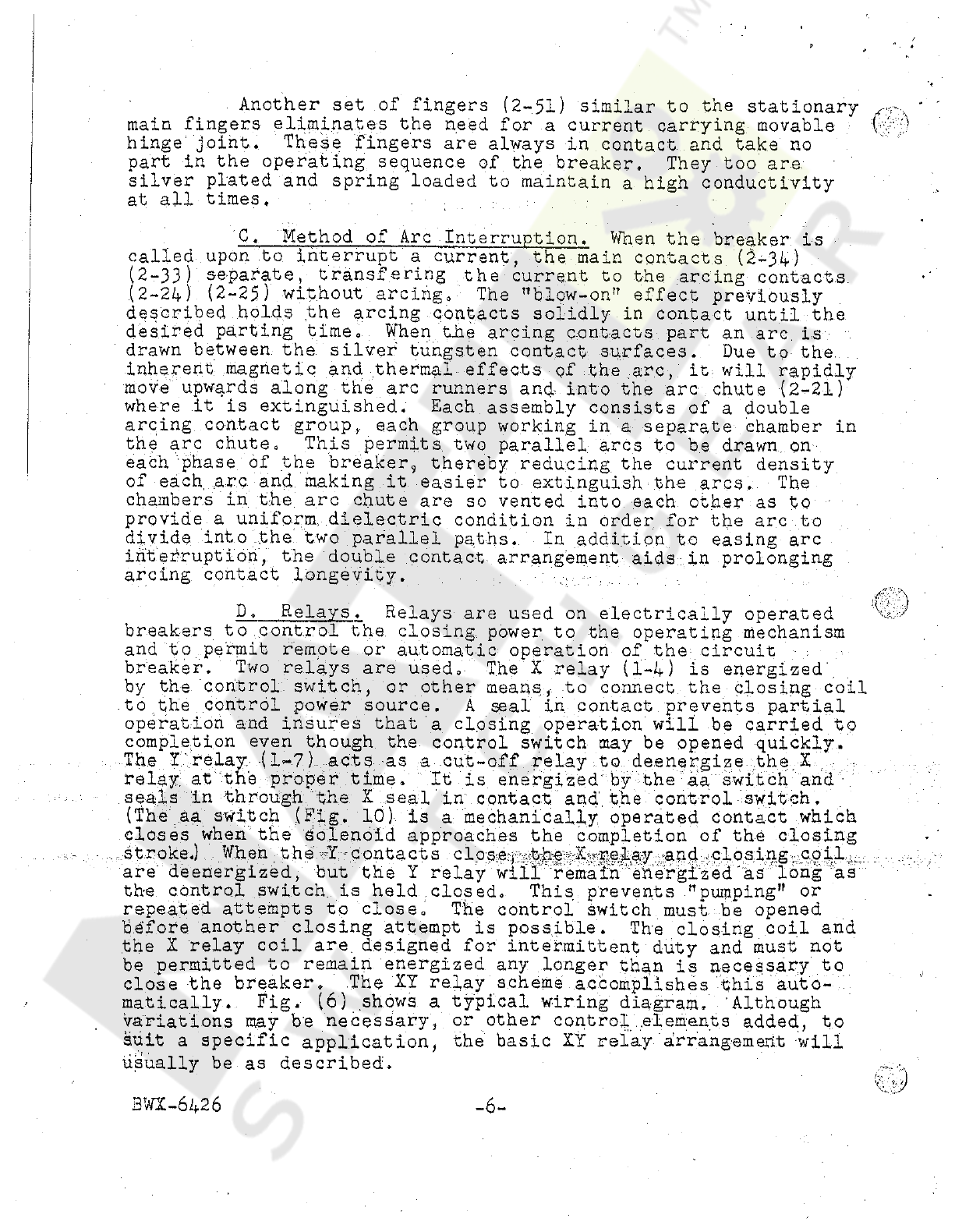
Another
set
of
fingers
(
2
-
51
)
similar
to
the
stationary
-
main
fingers
eliminates
the
need
,
for
a
current
carrying
movable
hinge
joint
.
These
fingers
are
always
in
contact
and
take
no
part
in
the
operating
sequence
of
the
breaker
.
They
too
are
silver
plated
and
spring
loaded
to
maintain
a
high
conductivity
at
all
times
.
V
-
>
'
C
.
Method
of
Arc
Interruption
.
When
the
breaker
is
called
upon
to
interrupt
a
current
,
the
main
contacts
(
2
-
34
)
(
2
-
33
)
separate
,
transfering
the
current
to
the
arcing
contacts
(
2
-
24
)
(
2
-
25
)
without
arcing
.
The
!
,
blow
-
on
"
effect
previously
described
holds
the
arcing
contacts
solidly
in
contact
until
the
desired
parting
time
.
.
When
the
arcing
contacts
part
an
arc
is
drawn
between
the
silver
tungsten
contact
surfaces
.
Due
to
the
Inherent
magnetic
and
thermal
effects
of
the
arc
,
it
will
rapidly
move
upwards
along
the
arc
runners
and
into
the
arc
chute
(
2
-
21
)
where
it
is
extinguished
.
Each
.
assembly
consists
of
a
double
arcing
contact
group
,
,
each
group
working
in
a
separate
chamber
in
the
arc
chute
.
This
permits
two
parallel
arcs
to
be
drawn
.
on
each
phase
of
the
breaker
,
thereby
reducing
,
the
current
density
of
each
,
arc
and
.
making
it
easier
to
extinguish
the
arcs
.
..
The
chambers
in
the
arc
chute
are
so
vented
into
each
other
as
to
provide
a
uniform
dielectric
condition
in
order
for
the
arc
to
divide
into
the
two
parallel
paths
,
interruption
,
arcing
contact
longevity
.
In
addition
to
easing
arc
the
double
contact
,
arrangement
aids
,
in
prolonging
D
.
Relays
Relays
are
used
on
electrically
operated
breakers
to
,
control
the
.
closing
power
to
the
operating
mechanism
and
to
permit
remote
or
automatic
operation
of
the
-
circuit
breaker
.
Two
relays
are
used
.
The
X
relay
(
1
-
4
)
is
energized
'
by
the
control
,
switch
,
or
other
means
,
to
connect
the
closing
coil
to
the
control
power
source
.
A
seal
in
contact
prevents
partial
operation
and
insures
that
a
closing
operation
will
be
carried
to
completion
even
though
the
control
switch
may
be
opened
quickly
.
The
I
relay
.
(
1
-
7
)
.
.
acts
as
a
cut
-
off
relay
to
deenergize
the
.
X
relay
at
the
proper
time
.
It
is
energized
by
the
aa
"
switch
and
seals
in
through
the
X
seal
in
contact
and
.
the
control
switch
,
(
The
aa
switch
(
Fig
.
10
)
is
a
mechanically
,
operated
contact
which
closes
when
the
solenoid
approaches
the
completion
of
the
closing
.
..
.
.
.
.
stroke
.
)
When
the
I
-
contacts
close
^
-
hhe
X
^
pqjLay
-
and
^
losing
^
cpil
are
deenergized
,
but
the
X
relay
will
remain
energized
as
long
as
the
control
switch
,
is
held
closed
.
This
prevents
"
pumping
"
or
repeated
attempts
to
close
.
The
control
switch
must
be
opened
before
another
closing
attempt
is
possible
.
The
closing
coil
and
the
X
relay
coil
are
.
designed
for
intermittent
duty
and
must
not
be
permitted
to
remain
energized
any
longer
than
is
necessary
to
close
the
breaker
.
.
The
XI
relay
scheme
accomplishes
this
auto
-
matically
.
Fig
.
(
6
)
shows
a
typical
wiring
diagram
.
'
Although
variations
may
be
necessary
,
or
other
control
.
elements
added
,
to
suit
a
specific
application
,
the
basic
XX
relay
,
arrangement
will
usually
be
as
described
.
’
u
.
J
'
BWX
-
62
,
26
-
6
-
Courtesy of NationalSwitchgear.com
A
-
A
Trip
Units
and
Accessory
Devices
.
E
.
.
Description
,
.
and
function
of
these
items
are
covered
in
"
Parts
V
and
VI
of
the
instruction
hook
.
PART
IV
MAINTENANCE
,
ADJUSTMENT
,
AND
REPLAC
.
EMENT
A
,
General
.
Occasional
checking
and
cleaning
of
the
breaker
will
promote
long
and
troublefree
service
.
Oiling
and
greasing
should
be
done
with
care
because
excess
oil
and
grease
tend
to
collect
dirt
which
in
time
might
make
operation
sluggish
and
affect
the
dielectric
strength
of
insulating
members
.
Always
refer
to
the
instruction
book
before
removing
parts
or
changing
adjustments
.
A
recheck
of
the
installation
inspection
(
Part
II
)
during
maintenance
will
indicate
the
overall
general
condition
of
the
breaker
B
.
Periodic
Inspection
.
A
periodic
inspection
and
servicing
should
be
included
in
the
breaker
maintenance
routine
.
A
semi
-
annual
inspection
is
usually
sufficient
,
however
,
in
cases
where
unfavorable
atmospheric
conditions
exist
,
more
frequent
.
inspections
are
recommended
.
In
any
case
,
the
total
'
number
of
breaker
operations
between
servicing
should
not
exceed
1750
for
the
LA
-
25
breaker
.
The
maintenance
check
list
(
Section
C
)
will
provide
a
ready
and
convenient
guide
to
a
thorough
and
under
-
standing
Inspection
of
the
breaker
.
Servicing
will
be
facilitated
if
a
tag
is
attached
to
each
unit
listing
date
,
operation
counter
reading
,
date
of
next
inspection
,
counter
reading
at
next
inspec
-
tion
,
and
serviceman
'
s
signature
.
-
C
.
Maintenance
Check
List
.
The
following
items
are
11
st
ed
for
-
c
onv
.
eni
enc
e
'
in
'
ma
intaining
the
equipment
in
the
'
best
.
possible
condition
.
By
periodically
checking
and
maintaining
these
items
,
the
breakers
will
provide
the
continued
satisfactory
service
of
which
they
are
capable
.
.
Cleaning
.
"
Remove
all
dust
,
dirt
and
foreign
material
.
Wipe
off
excess
oil
and
grease
.
Wipe
down
insulation
.
Clean
cam
faces
,
latch
rolls
and
latch
faces
.
Make
certain
that
dirt
or
oxidized
grease
is
not
interfering
with
moving
parts
.
2
.
Connections
.
Check
all
hardware
for
tightness
.
Check
for
loose
wiring
connections
and
broken
or
abraided
in
-
sulation
.
I
3
.
Contacts
.
Check
main
contacts
for
cleanliness
and
permanence
of
silver
plating
.
(
Main
contacts
should
not
be
dressed
.
)
Check
arcing
contacts
for
wear
,
and
arc
erosion
.
'
Contacts
should
be
replaced
if
arcing
alloy
shows
indications
of
wearing
BWX
-
6426
Courtesy of NationalSwitchgear.com

through
before
next
inspection
.
Arcing
contacts
should
also
be
.
replaced
if
,
with
arcing
contacts
(
2
-
24
)
arid
(
2
-
25
)
just
touching
a
1
/
8
"
dia
.
rod
cannot
be
passed
between
stationary
contact
fingers
(
2
-
33
)
and
movable
main
contact
(
2
-
34
)
,
4
.
Lubrication
.
Needle
bearing
are
packed
with
a
special
lubricant
and
should
need
no
further
attention
.
Bearing
pins
and
other
sliding
or
rotating
areas
should
be
wiped
with
a
light
film
of
"
Aero
Lubriplate
"
(
made
by
Fisk
Go
.
)
.
Lubrication
should
not
be
applied
excessively
and
must
be
kept
off
insulating
members
,
as
it
may
affect
dielectric
ability
and
cannot
be
satisfactorily
removed
.
5
.
Contact
-
Adjustment
.
Arcing
contacts
(
2
-
24
)
(
2
-
25
)
do
not
require
adjustment
.
Main
contacts
(
2
-
33
)
(
2
-
34
)
are
factory
.
adjusted
and
should
not
require
field
adjustment
unless
parts
have
been
disassembled
.
Adjustment
is
obtained
by
use
of
.
shims
(
2
-
18
)
between
the
operator
frame
(
2
-
15
)
and
the
.
breaker
frame
(
2
-
26
)
.
Main
contacts
are
in
proper
adjustment
when
there
is
a
clearance
of
1
/
64
"
to
l
/
l
6
"
between
the
bottom
of
the
stationary
main
contact
(
2
^
*
33
)
,
and
the
face
of
the
movable
main
contact
(
2
-
34
)
,
with
the
breaker
full
closed
.
All
contact
fingers
(
2
-
33
)
should
be
in
contact
at
the
"
knee
"
of
the
contact
and
open
at
the
bottom
.
:
Be
certain
that
there
is
.
aftertravel
in
springs
(
2
-
32
)
with
the
breaker
full
closed
.
vv
•
/
'
:
-
)
•
v
'
-
V
IS
6
Arcing
Contact
Hinge
Tension
.
Spring
washers
(
2
-
57
)
should
be
compressed
,
to
a
height
of
.
03
:
8
"
£
.
002
"
as
measured
with
(
2
-
58
)
and
flat
side
of
arcing
contact
4
feelers
between
washers
(
2
-
24
)
•
7
.
Trip
Latch
Adjustment
,
Trip
latch
(
2
-
43
)
should
have
a
tripping
force
of
2
to
3
-
^
.
oz
.
as
measured
at
right
angles
to
a
3
/
4
"
radius
(
pulling
in
line
with
the
centerline
of
screw
(
2
-
41
)
will
fulfill
this
condition
)
.
,
positioning
slotted
end
-
of
spring
(
2
-
42
)
tripp
ing
force
,
..
,
and
rcount
e
re
1
o
ckwi
se
to
in
ere
as
e
force
Force
may
be
changed
by
-
clockwise
to
decrease
the
tripping
.
.
•
:
Trip
latch
(
2
-
43
)
engagement
on
secondary
trip
lever
(
2
-
44
)
roll
should
be
3
/
l
6
"
i
'
1
/
16
"
.
.
.
Measurement
is
from
the
lead
-
ing
edge
of
t
rip
latch
face
to
the
line
of
contact
on
.
the
latch
face
.
Adjustment
is
obtained
by
positioning
screw
(
2
-
41
)
to
vary
the
angular
position
of
trip
latch
(
2
-
43
)
.
Trip
latch
roll
.
on
.
screw
(
2
-
41
)
may
have
up
to
l
/
32
"
clearance
to
trip
block
(
2
-
48
)
as
long
as
the
trip
latch
engagement
is
maintained
.
8
.
Manual
Closing
Lever
Overtravel
Stops
.
Two
over
-
travel
stop
screws
(
2
-
12
)
are
provided
.
The
one
to
the
right
of
manual
closing
cam
(
2
-
10
)
is
set
to
stop
the
manual
closing
lever
.
(
•
2
-
13
)
in
its
vertical
position
and
'
is
-
set
visually
.
The
-
left
-
hand
stop
screw
limits
travel
in
the
closed
position
and
is
set
.
/
Y
’
A
&
-
8
-
BWX
-
6426
Courtesy of NationalSwitchgear.com

to
provide
l
/
32
,
?
to
l
/
l
6
"
clearance
between
prop
latch
(
2
-
2
)
face
and
pin
on
main
closing
cam
(
2
-
5
)
when
the
hand
closing
cam
(
2
-
10
)
is
against
the
overtravel
stop
screw
.
9
.
Reset
Button
.
The
reset
button
(
14
-
6
)
is
adjusted
to
provide
l
/
l
6
n
to
1
/
3
"
clearance
between
reset
lever
(
11
-
10
)
on
the
breaker
and
trip
device
reset
lever
(
14
-
17
)
with
the
reset
shaft
(
14
-
1
)
on
the
trip
device
in
the
tripped
position
.
10
.
Operation
Counter
.
The
operation
counter
(
2
-
11
)
when
supplied
is
actuated
by
the
open
-
close
indicator
(
2
-
14
)
and
is
adjusted
such
that
the
counter
arm
has
some
overtravel
when
breaker
is
open
.
v
>
11
.
Limit
Switch
.
With
breaker
in
closed
and
latched
position
,
the
upper
contacts
(
10
-
3
)
(
10
-
9
)
of
limit
switch
(
10
-
3
)
should
have
1
/
32
”
fol
'
low
-
up
after
contact
make
.
Adjustment
is
by
use
of
shims
(
10
-
7
)
between
switch
and
mounting
pad
.
12
.
Closing
Solenoid
.
The
closing
solenoid
(
Fig
.
9
)
is
mounted
on
the
operating
mechanism
frame
(
2
-
15
)
and
pinned
in
position
.
Should
,
readjustment
ever
be
:
necessary
,
the
solenoid
is
to
be
positioned
and
repinned
such
that
with
the
solenoid
armature
(
9
-
13
)
tight
against
the
pole
head
(
9
-
5
)
to
hold
the
breaker
closed
,
the
main
closing
cam
(
9
-
1
)
will
have
1
/
3
"
clearance
to
its
overtravel
stop
(
9
-
10
)
,
and
the
prop
latch
(
9
-
6
)
face
will
have
l
/
l
6
rt
clearance
to
the
prop
latch
pin
(
9
-
7
)
.
After
securing
the
solenoid
mounting
screws
(
9
-
4
)
,
and
drilling
four
letter
"
F
"
(
.
257
”
dia
.
j
holes
for
the
locking
pins
49
-
11
.
)
but
before
insert
-
ing
pins
,
check
breaker
open
position
.
There
should
be
1
/
32
"
to
1
/
16
"
clearance
between
the
end
of
the
armature
cam
(
9
-
#
)
and
the
cam
pins
(
9
-
9
)
•
If
adjustment
is
necessary
,
remove
solenoid
and
rotate
solenoid
armature
stop
(
9
-
14
)
as
necessary
and
lock
with
set
screws
(
9
-
15
)
,
after
which
the
solenoid
is
replaced
on
the
breaker
and
pinned
in
place
.
Note
.
that
redrilling
for
locking
pins
is
not
necessary
for
normal
reassembly
-
only
when
adjustments
require
changing
.
D
.
Movable
Arcing
Contact
.
The
movable
arcing
contact
(
2
-
24
)
may
be
replaced
,
after
removing
arc
chutes
(
2
-
21
)
and
phase
barriers
(
2
-
20
)
,
by
removing
hardware
and
spring
washers
(
2
-
57
)
at
the
hinge
joint
of
the
arcing
contact
.
In
reassembling
make
certain
that
the
hinge
.
.
tension
is
correct
as
outlined
in
Section
IV
-
C
-
6
.
E
.
Stationary
Arcing
Contact
.
The
stationary
arcing
contact
(
21
^
37
may
be
replaced
,
after
removal
of
arc
chutes
and
phase
barriers
,
merely
by
removal
of
screws
(
2
-
27
)
and
(
2
-
23
)
.
Replacement
is
obvious
and
no
adjustment
is
required
.
\
:
•
tv
3
BWX
-
6426
•
•
^
Courtesy of NationalSwitchgear.com

I
F
.
Movable
Main
Contact
.
The
movable
main
contact
(
2
-
34
)
is
best
removed
as
a
unit
,
including
the
arcing
contact
.
The
outside
-
contacts
must
be
removed
before
the
center
phase
contact
can
be
removed
.
Contacts
will
be
free
for
removal
when
the
hinge
pin
is
removed
.
Since
the
hinge
pin
is
under
pressure
from
the
hinge
.
joint
contact
fingers
(
2
-
51
)
,
care
must
be
used
not
to
score
or
damage
.
the
pin
.
.
In
replacing
movable
contacts
be
certain
that
all
three
phases
are
lined
up
on
shaft
(
2
-
560
to
insure
smooth
operation
and
freedom
from
binds
.
G
.
Stationary
Main
Contacts
.
To
remove
the
lower
main
contact
block
(
2
-
5
Cj
,
first
remove
movable
contact
assembly
(
2
-
34
)
as
outlined
in
Part
IV
-
F
then
screws
(
2
-
49
)
and
(
2
-
36
}
.
If
desirable
,
contact
block
(
2
-
50
)
and
moving
contact
unit
(
2
.
-
34
)
can
be
removed
as
a
group
on
the
outside
phases
.
Then
,
after
removing
the
main
shaft
.
(
2
-
56
)
,
the
center
phase
assembly
can
be
removed
.
To
remove
upper
main
contact
block
(
2
-
30
)
,
first
remove
movable
main
contact
(
2
-
34
)
.
as
'
outlined
“
in
Part
IV
-
F
,
then
screws
(
2
-
31
)
and
(
2
-
27
)
,
permitting
contact
block
(
2
-
30
)
.
and
stationary
arcing
contact
(
2
-
25
)
to
be
removed
as
a
group
.
Once
,
the
above
members
are
removed
,
it
is
a
simple
matter
to
replace
contact
fingers
,
.
(
2
-
33
)
and
(
2
-
51
)
.
,
Remove
fingers
under
a
cloth
or
other
shield
to
prevent
springs
from
flying
free
.
A
screw
-
driver
may
be
used
to
work
springs
and
fingers
to
'
the
ends
of
the
block
for
removal
.
Be
careful
not
to
raise
nicks
or
burrs
or
otherwise
damage
contact
fingers
.
Note
that
spring
(
2
-
37
)
consists
of
a
.
double
(
inner
and
outer
)
spring
,
.
while
.
spring
(
2
-
32
)
is
a
single
spring
.
During
reassembly
of
upper
and
lower
contact
\
blocks
there
are
no
particular
adjustments
.
to
observe
,
however
,
alignment
between
the
three
phases
is
important
to
insure
that
the
main
operating
shaft
(
2
-
56
)
is
free
of
binds
and
that
,
the
complete
assembly
works
smoothly
and
easily
.
.
.
H
.
Trip
Units
and
Accessory
Devices
.
For
maintenance
,
adjustment
,
and
replacement
of
these
devices
refer
to
Parts
V
and
VI
of
the
instruction
book
,
where
detailed
instructions
will
be
found
.
)
'
.
v
{
-
f
I
.
Operating
Mechanism
(
Manual
)
.
The
manually
operated
mechanism
is
fastened
to
the
breaker
panel
frame
by
•
four
screws
(
2
-
17
)
.
Shims
(
2
-
16
)
are
used
to
adjust
main
contacts
(
see
section
XV
-
C
-
5
)
and
must
not
be
changed
for
any
.
other
reason
.
The
operator
may
be
removed
from
the
breaker
by
disconnecting
breaker
operating
link
(
2
-
52
)
and
removing
‘
four
screws
(
2
-
17
)
,
carefully
noting
amount
of
shims
(
2
-
16
)
.
After
reassembly
,
pay
particular
atten
-
tion
to
trip
latch
adjustments
and
main
contact
adjustments
to
be
certain
they
have
not
changed
.
Check
mechanisms
for
ease
of
.
operation
and
freedom
from
binds
.
4
)
'
BWX
-
6426
-
10
-
Courtesy of NationalSwitchgear.com
4
:
;
:
^
Operating
Mechanism
(
Electrical
)
J
The
electrical
operating
mechanism
is
exactly
the
same
as
the
manual
mechanism
with
the
addition
of
an
electrical
solenoid
and
accessories
to
accomplish
the
closing
operation
.
The
manual
closing
means
is
retained
,
as
in
the
manually
operated
breaker
.
The
.
operating
mechanism
and
solenoid
can
be
removed
as
a
unit
as
described
in
section
IV
-
X
,
after
disconnecting
the
closing
coil
and
limit
-
switch
leads
.
Should
the
solenoid
be
removed
from
the
operating
mechanism
,
it
must
be
carefully
readjusted
on
assembly
as
out
-
lined
in
section
IV
-
C
-
12
.
A
D
.
C
.
solenoid
is
furnished
for
-
use
with
a
direct
current
control
source
.
When
the
breaker
is
to
be
operated
from
an
alternating
current
source
,
an
A
.
C
.
solenoid
is
furnished
.
Thus
,
rectifiers
and
aging
resistors
are
not
required
.
*
.
K
,
Closing
Coil
,
.
Removal
of
.
the
closing
coil
(
9
-
16
)
requires
that
the
solenoid
.
(
Fig
.
.
9
)
be
.
removed
from
the
breaker
.
.
This
is
accomplished
by
removing
'
locking
pins
(
9
-
11
)
and
screws
(
9
-
4
)
.
With
the
solenoid
removed
,
the
armature
stop
(
9
-
14
)
can
be
removed
,
,
(
after
marking
it
for
replacement
at
the
same
setting
)
,
permitting
the
armature
.
to
be
withdrawn
and
the
coil
,
removed
.
After
replacing
coil
,
.
mount
and
adjust
solenoid
as
outlined
in
section
IV
-
C
-
12
,
making
sure
that
all
.
connections
are
made
up
tight
.
'
.
;
.
’
.
.
..
"
„
4
-
3
)
:
PART
V
.
PROTECTIVE
;
DEVICES
;
A
.
Series
Overcurrent
Trip
Device
Assembly
Adjustment
and
Calibration
.
Series
'
”
over
current
trip
devices
used
on
low
voltage
breakers
function
to
trip
the
breaker
whenever
the
current
through
the
breaker
exceeds
a
predetermined
value
.
This
device
includes
-
a
series
coil
,
magnetic
circuit
with
two
armatures
,
and
•
a
?
sealed
oil
time
delay
device
.
This
arrangement
is
varied
some
-
what
on
current
ratings
above
600
amps
,
on
the
LA
-
50
,
and
the
M
-
75
breakers
,
in
that
the
trip
device
coil
is
not
tied
to
the
lower
contact
.
structure
,
but
is
linked
to
an
inductive
series
coil
mounted
on
the
fixed
bus
in
the
rear
of
the
breaker
.
Figure
12
show
§
the
arrangement
of
the
functional
components
of
this
device
and
Figures
15
,
16
give
the
inverse
time
delay
characteristics
The
trip
elements
available
in
the
various
categories
of
series
trip
devices
are
three
in
number
and
calibrated
in
the
fallowing
ranges
.
,
*
Long
time
delay
element
-
for
use
in
combination
with
the
adjustable
instantaneous
trip
and
/
or
the
short
time
delay
element
.
The
pick
up
of
the
long
time
delay
element
is
'
adjustable
in
the
field
to
SO
,
100
,
120
,
140
,
or
160
%
pickup
of
the
BWX
-
6426
-
11
-
Courtesy of NationalSwitchgear.com
continuous
current
rating
of
the
trip
coil
.
Calibration
settings
r
.
,
v
.
in
excess
of
.
.
100
$
do
not
permit
the
continuous
current
rating
to
exceed
100
$
of
the
series
coil
rating
.
'
wt
'
Short
time
delay
element
-
for
use
in
combination
with
the
adjustable
instantaneous
element
and
/
or
the
long
time
delay
element
on
selective
trip
systems
.
The
pickup
of
the
short
time
delay
element
is
adjustable
in
the
field
to
500
,
750
and
1000
$
.
pickup
of
the
continuous
current
rating
of
the
trip
coil
.
•
••
•
’
I
Instantaneous
trip
element
-
for
use
in
combination
with
the
long
and
short
time
delay
elements
.
The
pickup
of
the
instantaneous
trip
element
is
adjustable
in
the
field
between
500
and
1500
$
pickup
of
the
continuous
current
rating
of
the
trip
coil
.
The
series
overcurrent
trip
devices
are
factory
adjusted
and
calibrated
and
should
not
be
disturbed
in
the
field
Without
proper
.
equipment
and
knowledge
of
the
device
,
'
The
operation
of
the
long
time
delay
element
(
12
-
15
)
is
as
follows
:
When
the
magnetic
pull
on
the
armature
(
12
-
15
)
increases
sufficiently
due
to
an
overcurrent
condition
in
the
series
coil
(
l
2
-
7
)
,
the
armature
(
12
-
15
)
will
pick
up
and
rotate
about
shaft
(
12
-
4
)
.
This
magnetic
attraction
must
overcome
the
tension
in
the
pickup
spring
(
12
-
20
)
and
also
displace
the
silicone
oil
in
time
delay
device
(
12
-
14
)
from
the
lower
chamber
to
the
upper
chamber
through
the
accurately
controlled
metering
'
element
(
12
-
12
)
.
As
the
armature
closes
the
'
gap
to
-
the
core
(
12
-
d
)
,
it
engages
,
trip
block
(
2
-
4
d
)
and
trips
the
breaker
.
When
the
breaker
has
tripped
,
the
armature
will
reset
against
stop
(
12
-
10
)
due
to
tension
in
'
pick
up
spring
.
Quick
reset
Is
provided
by
means
of
the
check
valve
(
12
-
13
)
in
time
delay
device
.
The
short
time
delay
element
(
12
-
18
)
functions
in
the
same
manner
as
the
long
time
element
.
The
one
major
difference
between
the
two
elements
is
that
the
short
time
delay
device
(
12
-
19
)
.
has
a
coarser
metering
element
.
The
time
delay
devices
for
the
long
and
short
time
delay
elements
are
not
interchangeable
and
are
clearly
marked
in
that
the
cover
on
the
long
'
time
delay
device
is
red
and
the
short
time
delay
device
is
green
.
The
time
delay
band
adjustments
for
the
two
inverse
time
elements
are
adjustable
by
locating
the
plunger
(
12
-
1
)
of
the
time
delay
device
in
'
.
the
proper
mounting
hole
as
marked
on
the
extensions
of
the
trip
elements
.
To
decrease
time
band
move
plunger
location
closer
to
shaft
(
12
-
4
)
of
armature
and
to
increase
move
plunger
away
from
shaft
.
This
relocation
of
the
plunger
varies
the
force
applied
to
the
time
delay
device
by
changing
the
lever
arm
and
also
changing
the
stroke
'
required
for
tripping
.
Each
time
.
band
,
,
maximum
,
intermediate
or
minimum
,
is
marked
by
a
white
band
'
indicating
the
'
mounting
.
point
for
the
time
delay
device
plunger
.
All
of
-
the
band
'
locations
are
m
.
)
v
'
t
.
-
.
y
BWX
-
6426
-
12
-
Courtesy of NationalSwitchgear.com

*
-
i
fm
progressive
and
if
desired
,
intermediate
settings
may
be
made
between
.
the
calibrated
-
points
.
.
for
finer
selectivity
.
The
-
pickup
calibration
of
the
armatures
is
selected
•
,
by
.
rotating
knob
(
12
-
2
)
which
moves
the
calibration
label
(
12
-
3
)
to
the
required
setting
.
Adjustment
of
the
calibration
label
increases
or
decreases
tension
in
the
pickup
spring
and
is
factory
calibrated
for
values
of
pickup
current
.
INSPECTION
AND
ADJUSTMENT
The
series
trip
device
should
be
inspected
prior
to
being
put
in
service
to
see
that
the
pick
up
calibration
and
time
delay
band
selections
are
in
accordance
with
the
application
requirements
,
'
This
device
leaves
the
factory
with
the
following
standard
settings
unless
otherwise
specified
in
the
purchase
order
:
Long
time
delay
element
is
set
at
100
%
pick
.
up
on
the
intermediate
time
delay
band
.
Short
time
delay
element
is
set
at
750
%
pick
up
on
the
intermediate
time
delay
band
.
Instantaneous
trip
element
is
sst
at
£
00
%
pickup
.
Selections
other
than
those
already
-
made
to
the
device
do
/
mob
;
*
-
.
require
further
testing
in
that
the
unit
is
completely
calibrated
at
the
factory
.
The
current
rating
of
the
series
coil
is
stamped
on
the
breaker
Nameplates
and
should
be
checked
in
applications
involving
varied
current
ratings
.
;
•
V
MAINTENANCE
AND
REPLACEMENT
The
individual
phase
series
trip
device
assemblies
j
are
mounted
on
a
common
base
and
must
be
removed
from
the
breaker
for
maintenance
or
replacement
as
one
assembly
.
To
remove
this
assembly
,
detach
the
assembly
mounting
bolts
(
2
-
39
)
,
and
.
screws
(
2
-
47
)
'
.
and
(
2
-
49
)
holding
the
series
overcurrent
coils
(
12
-
7
)
to
the
contact
structureHaving
removed
the
assembly
,
from
the
breaker
each
,
single
phase
assembly
can
then
be
detached
from
the
common
base
by
.
the
removal
of
four
mounting
screws
(
14
-
15
)
and
the
reset
shaft
(
14
-
1
)
.
To
remove
series
coil
(
12
-
7
)
which
does
not
require
a
.
single
phase
disassembly
,
detach
the
four
mounting
screws
(
12
-
5
)
holding
core
assembly
(
12
-
£
)
in
place
and
slide
the
complete
core
assembly
out
of
the
device
.
The
series
coil
will
then
slide
off
the
core
leg
and
can
be
assembled
in
the
reverse
steps
.
Gare
-
must
be
taken
at
assembly
that
the
two
screws
(
12
-
5
)
,
holding
the
'
core
in
the
assembly
next
to
the
armature
shaft
(
12
-
4
)
be
securely
tightened
before
the
other
two
screws
.
To
remove
time
delay
devices
(
L
2
-
14
)
or
(
19
)
remove
either
side
plate
from
the
single
phase
assembly
,
detach
the
time
delay
device
plunger
(
12
-
1
)
from
the
trip
armature
and
slide
the
device
BWX
-
6426
-
13
-
Courtesy of NationalSwitchgear.com

/
•
out
of
the
top
of
the
assembly
.
The
time
delay
device
is
a
sealed
,
unit
which
is
factory
adjusted
and
cannot
be
repaired
in
the
field
.
In
like
manner
,
the
calibration
-
labels
(
12
-
3
)
are
also
factory
calibrated
for
values
of
trip
current
and
calibration
label
locking
screw
(
12
-
25
)
•
should
not
be
disturbed
at
any
time
.
Parts
of
individual
devices
,
such
as
pickup
springs
and
calibra
-
tion
labels
,
must
n
.
ot
be
interchanged
between
devices
,
or
cali
-
brations
will
be
lost
.
The
individual
armature
trip
screws
(
12
-
9
)
are
factory
set
in
a
jig
,
and
should
not
require
adjustment
on
the
breaker
.
The
adjustments
of
these
armature
trip
screws
may
be
checked
by
closing
the
armature
to
1
/
8
”
air
gap
at
the
lower
edge
of
the
face
of
the
upper
core
'
leg
at
which
point
the
trip
screw
should
just
engage
the
trip
block
(
2
-
484
B
,
Thermal
Magnetic
Overcurrent
Trip
Device
Assembly
.
The
thermal
magnetic
trip
device
is
mounted
and
functions
to
trip
the
'
Breaker
in
the
same
manner
as
the
series
overcurrent
trip
device
,
excepting
that
the
time
delay
is
accomplished
by
means
of
a
thermal
element
.
This
device
includes
a
series
coil
,
magnetic
circuit
with
two
armatures
,
spiral
wound
bimetallic
element
,
nichrome
wire
heater
coil
and
a
secondary
coil
.
This
arrangement
varies
.
in
the
same
manner
as
the
series
overcurrent
device
for
ratings
on
the
LA
-
50
and
LA
-
75
which
use
the
series
inductive
coil
(
see
paragraph
A
of
section
V
)
.
Figure
13
shows
the
arrange
-
ment
of
the
functional
components
of
this
device
and
figure
16
illustrates
the
inverse
time
delay
characteristics
.
Each
thermal
magnetic
trip
device
is
calibrated
and
tested
prior
to
leaving
the
factory
and
should
not
be
disturbed
in
the
field
without
proper
equipment
and
knowledge
of
the
device
.
The
thermal
magnetic
trip
armature
pickup
is
adjustable
in
the
field
to
80
,
100
and
120
%
pickup
of
the
continuous
current
rating
of
the
series
-
trip
coil
.
This
selection
is
made
by
rotating
knob
(
13
-
6
)
on
the
front
of
the
device
to
'
the
desired
calibration
setting
.
The
device
nameplate
(
13
-
4
)
attached
to
the
front
of
the
-
device
has
etched
on
it
the
time
delay
characteristic
curves
which
enables
the
operator
to
easily
select
the
proper
settings
.
Calibration
settings
in
'
excess
of
100
%
do
not
permit
the
continu
-
ous
current
rating
to
exceed
100
%
of
the
series
coil
rating
.
The
thermal
magnetic
trip
armature
(
13
-
19
)
functions
to
trip
the
breaker
in
the
following
manner
:
When
an
overcurrent
condition
exists
in
the
series
coil
(
13
-
12
)
,
it
causes
a
similar
overcurrent
in
the
secondary
coil
(
13
-
9
)
due
to
the
transformer
'
action
in
the
fixed
armature
(
13
-
16
)
.
This
overcurrent
condition
in
the
secondary
coil
generates
heat
to
the
spiral
wound
bimetallic
element
(
13
-
3
)
by
means
of
the
nichrome
wire
heater
coil
(
13
-
2
)
which
surrounds
this
element
.
The
heat
generated
in
the
heater
coil
(
13
-
2
)
causes
the
free
end
of
the
bimetallic
element
(
13
-
3
)
to
rotate
along
with
cam
(
13
-
5
)
which
is
fastened
to
it
.
On
V
.
•
rV
"
)
'
-
.
V
.
BWX
-
6426
-
14
-
Courtesy of NationalSwitchgear.com
Table of contents
Other Allis-Chalmers Circuit Breaker manuals

Allis-Chalmers
Allis-Chalmers LA-600 User manual

Allis-Chalmers
Allis-Chalmers LA-600 User manual

Allis-Chalmers
Allis-Chalmers LA-1600 User manual

Allis-Chalmers
Allis-Chalmers FB-500A-FC-750A User manual

Allis-Chalmers
Allis-Chalmers LA-1600 User manual

Allis-Chalmers
Allis-Chalmers MA-75B User manual

Allis-Chalmers
Allis-Chalmers LA 3000 User manual

Allis-Chalmers
Allis-Chalmers MA-75 User manual

Allis-Chalmers
Allis-Chalmers LA-600 User manual


