Allmand NIGHT-LITE PRO II Quick start guide

#3 BLACK #4 BLACK#1 BLACK
BLACK
RED W/ BLACK STRIPE
RED
BLUE
YELLOW
ORANGE
WHITE W/
BLACK STRIPE
#1 GREEN
#2 GREEN
#3 GREEN
#4 GREEN
#1 WHITE
#2 WHITE
#3 WHITE
#4 WHITE
JUNCTION BOX
#1 LAMP #2 LAMP #3 LAMP #4 LAMP
3 PORT
LEVER
LOCK
2 PORT
LEVER
LOCK
2 PORT
LEVER
LOCK
2 PORT
LEVER
LOCK
2 PORT
LEVER
LOCK
2 PORT
LEVER
LOCK
#2 BLACK
3 PORT
LEVER
LOCK
16 GA GREEN
16 GA
GREEN
6 PORT
PUSH-IN
CONNECTOR
BROWN
Wire Schematic Manual
50 & 60Hz NIGHT-LITE PRO II™
Copyright © 2016 Allmand Bros., Inc.
Holdrege, NE, USA. All rights reserved.
Part No.: 108811
Revision: A
en
www.allmand.com
Portable
Industrial
Heaters
Portable
Light Towers
Portable
Light Stands
Solar Flashing
Arrow Boards
Reliability, Performance, and Integrity Since 1938
Brighter. Warmer. Safer.
LIGHT TOWER APP
Not for Reproduction
Allmand Product Name Schematic Manual
©2016 Allmand™ Bros., Inc.
TABLE OF CONTENTS
SLS Key Start Schematic (105894) .......................................................................(1.1)
LSC Schematic (105895) ........................................................................................(1.2)
CAT C1.1 Schematic (105888) ..............................................................................(1.3)
CAT C1.1 Voltage Regulator Schematic (105899) ...............................................(1.4)
CAT C1.1 LSC Schematic (105904) ......................................................................(1.5)
Kubota D1005/1105 Schematic (105893) ..............................................................(1.6)
Kubota D1005/1105 LSC Schematic (105905) .....................................................(1.7)
Shocker Valve Schematic (106156) .......................................................................(1.8)
Low Fuel Module Schematic (105901) ..................................................................(1.9)
Low Fuel Beacon Schematic (105897) ...............................................................(1.10)
Low Fuel Sender Schematic (106341) ...............................................................(1.11)
Heated Fuel/Water Separator (105886) ................................................................(1.12)
4 Light 14/7 Cord Schematic (105291) ...............................................................(1.13)
4 Light 16/8 Cord Schematic (105292) ...............................................................(1.14)
4 Light LED Schematic (105713) ........................................................................(1.15)
4 Light LED Disconnect Schematic (106157) ....................................................(1.16)
4 Light Relay Schematic (105898) ......................................................................(1.17)
1000W 60Hz 120V Ballast Schematic (105287) .................................................(1.18)
1000W 50Hz 120V Ballast Schematic (105289) .................................................(1.19)
1250W 60Hz 120V Ballast Schematic (105286) .................................................(1.20)
Up/Down Momentary Switch Schematic (105935) ................................................(1.21)
Up/Down Momentary Switch w/ Alarm Schematic (105936) .................................(1.22)
Push Switch Schematic (106154) ..........................................................................(1.23)
Int’l Generator to Lights Schematic (106337) ......................................................(1.24)
Int’l Schuko Panel Schematic (105513) ...............................................................(1.25)
Int’l Tail Light Schematic (105502) .......................................................................(1.26)
Tail Light Schematic (107266) ................................................................................(1.27)
Marker Lights Schematic (107267) .......................................................................(1.28)
Interior Work Light Schematic (105896) ..............................................................(1.29)
LED Driver 4 Light Schematic (105632) ..............................................................(1.30)
License Plate LED Lamp Schematic (105350) .....................................................(1.31)
SLS 1.1 Relay Addition Schematic (106877) ......................................................(1.32)
LSC 2.1 120V Transformer Schematic (106885) .................................................(1.33)
i
Not for Reproduction

Allmand Product
Allmand Product Name Schematic Manual
©2016 Allmand™ Bros., Inc.
ii
TABLE OF CONTENTS
2-20AMP GFCI Schematic (107599) ..................................................................(1.34)
1-20AMP GFCI Schematic (107620) ..................................................................(1.35)
2-30AMP RV Schematic (107624) .....................................................................(1.36)
1-30AMP RV 1-20AMP GFCI Schematic (107621) .........................................(1.37)
1-30AMP Twistlock 1-20AMP GFCI Schematic (107628) ...............................(1.38)
No Outlet Schematic (107627) .............................................................................(1.39)
GPS ZTR System Schematic (105345) ..............................................................(1.40)
Emergency Stop Schematic (105903) .................................................................(1.41)
102 Decibel Alarm Schematic (108035) .............................................................(1.42)
Not for Reproduction
Allmand Product Name Schematic Manual
©2016 Allmand™ Bros., Inc.
WIRE SCHEMATIC PAGE CONNECTION TABLE (1 of 4)
iii
Schematic Page 1st Connection
Page(s)
2nd Connection
Page(s)
3rd Connection
Page(s)
4th Connection
Page(s)
CAT C1.1 Schematic 1.1 and 1.4 1.11 1.1 1.1
CAT C1.1 Voltage Regulator
Schematic 1.3 or 1.5 1.1 or 1.2 n/a n/a
CAT C1.1 LSC Schematic 1.2 or 1.4 1.11 1.2 1.2
Kubota D1005/1105
Schematic 1.1 1.11 1.1 1.1
Kubota D1005/1105 LSC
Schematic 1.2 1.11 1.2 1.2
Shocker Valve Schematic n/a n/a n/a n/a
Schematic Page 1st Connection
Page(s)
2nd Connection
Page(s)
3rd Connection
Page(s)
4th Connection
Page(s)
SLS Key Start Schematic 1.40 1.9, 1.12, and/or
1.29 1.4 1.32
LSC Schematic 1.10 1.33 1.11 1.12 and/or 1.29
Schematic Page 5th Connection
Page(s)
6th Connection
Page(s)
7th Connection
Page(s)
8th Connection
Page(s)
SLS Key Start Schematic 1.17 1.3 or 1.6 1.3 or 1.6 1.3, 1.4, and/or
1.6
LSC Schematic 1.4 1.5 or 1.7 1.4, 1.5, and/or
1.7 1.17
Schematic Page 9th Connection
Page(s)
10th Connection
Page(s)
11th Connection
Page(s)
12th Connection
Page(s)
LSC Schematic 1.5 or 1.7 1.42 1.4 n/a
Not for Reproduction
Allmand Product
Allmand Product Name Schematic Manual
©2016 Allmand™ Bros., Inc.
iv
WIRE SCHEMATIC PAGE CONNECTION TABLE (2 of 4)
Schematic Page 1st Connection
Page(s)
2nd Connection
Page(s)
3rd Connection
Page(s)
4th Connection
Page(s)
Low Fuel Module Schematic 1.11 1.10 1.1 n/a
Low Fuel Beacon Schematic 1.2 or 1.9 n/a n/a n/a
Low Fuel Sender Schematic 1.2, 1.3, or 1.6 n/a n/a n/a
Heated Fuel/Water
Separator 1.1 or 1.2 n/a n/a n/a
4 Light 14/7 Cord Schematic 1.18, 1.19, or
1.20 n/a n/a n/a
4 Light 16/8 Cord Schematic 1.18, 1.19, or
1.20 n/a n/a n/a
4 Light LED Schematic 1.30 n/a n/a n/a
4 Light LED Disconnect
Schematic 1.30 n/a n/a n/a
4 Light Relay Schematic 1.1 or 1.2 1.18, 1.19, 1.20,
or 1.30
1.34, 1.35, 1.36,
1.37, 1.38, or 1.39 n/a
1000W 60Hz 120V Ballast
Schematic
1.13, 1.14, or
1.17 n/a n/a n/a
1000W 50Hz 120V Ballast
Schematic
1.13, 1.14, or
1.17 n/a n/a n/a
1250W 60Hz 120V Ballast
Schematic
1.13, 1.14, or
1.17 n/a n/a n/a
Up/Down Momentary Switch
Schematic 1.23 n/a n/a n/a
Up/Down Momentary Switch
w/ Alarm Schematic 1.23 n/a n/a n/a
Not for Reproduction

Allmand Product Name Schematic Manual
©2016 Allmand™ Bros., Inc.
WIRE SCHEMATIC PAGE CONNECTION TABLE (3 of 4)
v
Schematic Page 1st Connection
Page(s)
2nd Connection
Page(s)
3rd Connection
Page(s)
4th Connection
Page(s)
Push Switch Schematic 1.21 or 1.22 n/a n/a n/a
Int’l Generator to Lights
Schematic 1.25 n/a n/a n/a
Int’l Schuko Panel
Schematic 1.24 n/a n/a n/a
Int’l Tail Light Schematic n/a n/a n/a n/a
Tail Light Schematic 1.31 1.28 n/a n/a
Marker Lights Schematic 1.27 n/a n/a n/a
Interior Work Light
Schematic 1.1 or 1.2 n/a n/a n/a
LED Driver 4 Light
Schematic 1.17 1.15 or 1.16 n/a n/a
License Plate LED Lamp
Schematic 1.27 n/a n/a n/a
SLS 1.1 Relay Addition
Schematic
1.17, 1.34, 1.35, 1.36,
1.37, 1.38, or 1.39 1.1 n/a n/a
LSC 2.1 120V Transformer
Schematic
1.17, 1.34, 1.35, 1.36,
1.37, 1.38, or 1.39 1.2 n/a n/a
2-20AMP GFCI Schematic 1.17 n/a n/a n/a
1-20AMP GFCI Schematic 1.17 n/a n/a n/a
2-30AMP RV Schematic 1.17 n/a n/a n/a
Not for Reproduction
Allmand Product
Allmand Product Name Schematic Manual
©2016 Allmand™ Bros., Inc.
vi
Schematic Page 1st Connection
Page(s)
2nd Connection
Page(s)
3rd Connection
Page(s)
4th Connection
Page(s)
1-30AMP RV 1-20AMP GFCI
Schematic 1.17 n/a n/a n/a
1-30AMP Twistlock 1-20AMP
GFCI Schematic 1.17 n/a n/a n/a
No Outlet Schematic 1.17 n/a n/a n/a
GPS ZTR System Schematic 1.1 n/a n/a n/a
Emergency Stop Schematic 1.3, 1.5, 1.6, or
1.7 n/a n/a n/a
102 Decibel Alarm
Schematic 1.2 n/a n/a n/a
WIRE SCHEMATIC PAGE CONNECTION TABLE (4 of 4)
Not for Reproduction

Allmand Product Name Schematic Manual
©2016 Allmand™ Bros., Inc.
1.1 - SLS Key Start Schematic
1.1
Battery (+)
Fuel Solenoid
Light Relay #1
Light Relay #2
Light Relay #3
Glow Plug
50A
5A
30A
68 Ohm
Starter Solenoid
Oil Pressure SW
Coolant Temp SW
Alt (See Secification 1)
15A
Fuel Pump-If equiped
Female Spade
for EG Power
and A2/CH
on Isuzu EG
Module and J1
Pin 9 on Cat EG
module.
ENGINE HARNESS
CONNECTOR 1
ENGINE HARNESS
CONNECTOR 2
Harness Ground
7.5A
35A
35A
Cat 1.1 Alt (LT Blue)
Cat 1.1 Alt (Blue)
12AWG BLACK
14AWG YELLOW
12AWG BLUE
16AWG GREEN
14AWG YELLOW
14AWG ORANGE
16AWG BLACK
16AWG
RED
16AWG
RED
16AWG
RED
12AWG RED
14AWG YELLOW
12AWG RED
14AWG
BLUE/
WHITE
16AWG RED
16AWG GRAY
16AWG BROWN
14AWG BLUE/WHITE
16AWG RED
16AWG RED
16AWG RED
16AWG GRAY
16AWG
BROWN/ORANGE
16AWG TAN
12AWG RED
12AWG RED
12AWG RED
CONNECT TO
10AWG BLUE
WIRE FROM
HARNESS
14AWG RED
H
TIMER
14AWG RED
16AWG RED
12AWG
YELLOW
16AWG
RED
12AWG
YELLOW
14AWG YELLOW
16AWG GREEN
Accessory
SLS Relay Addition
SLS CONNECTOR
1 & 6
4 & 5
3
2
16AWG RED
105894_A
2nd Connection
(TO 1.3,
OR 1.6)
6th Connection
(TO 1.4)
3rd Connection
(TO 1.32)
4th Connection
(TO 1.40)
1st Connection
(TO 1.17)
5th Connection
7th Connection
8th Connection
(TO 1.3,
OR 1.6)
(TO 1.3, 1.4,
AND/OR 1.6)
(TO 1.9, 1.12,
AND/OR 1.29)
Not for Reproduction
Allmand Product
Allmand Product Name Schematic Manual
©2016 Allmand™ Bros., Inc.
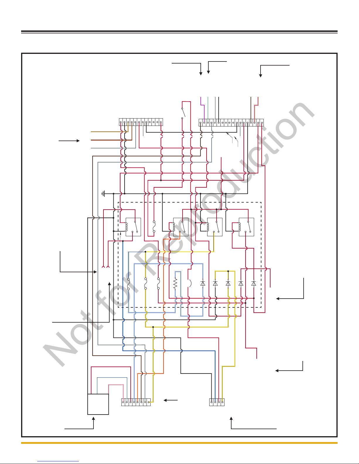
1.2 - LSC Schematic
1.2
Engine Harness
Connector 1
Engine Harness
Connector 2
SLS
Connector
LSC Connector
Beacon
Alarm
GPS CAN L
GPS CAN H
Fuel Level
Sender
R1
R2
R3
R4
D1
D2
D3
D4
D5
CB1
F1
F2
F3
Electronic
Governor
Power
(A2/CH Isuzu 4LE
and J1 Pin 9 Cat 1.5T)
OR
Cat 1.1Voltage Regulator
Yellow Wire
1
2
3
4
1
2
3
4
6
5
7
8
1
2
3
4
5
6
7
8
9
10
11
12
13
14
15 16
17
18
1
2
3
4
5
6
7
8
9
10
11
12
Cat 1.1
Voltage
Regulator
(Optional)
Main PWR
Switch
RS1
F5
Block
Heater
Accessory
BATT (+)
16 AWG
YLW/PPL
16AWG BRN
16AWG BLK
16AWG WHT
16AWG PPL
16AWG RED
16AWG RED
16AWG RED
16AWG BLK
16AWG BLK
16AWG WHT
16AWG GRAY
16AWG BRN
16AWG RED
16AWG RED
16AWG RED
14AWG YLW
14AWG YLW
16AWG BLK
16AWG BLK
16AWG BLK
12AWG BLK
16AWG BLK
16AWG RED
16AWG BLK
16AWG RED
12AWG RED
12AWG
RED
12AWG
RED
12AWG RED
12AWG RED
12AWG RED
14AWG RED
14AWG YLW
16AWG GRAY
16AWG TAN
16AWG BRN/ORG
16AWG RED
16AWG RED
16AWG RED
16AWG BLK
12AWG BLU
14AWG BLK
14AWG PINK
14AWG
BLU/WHT
14AWG RED
14AWG ORG
14AWG BLU/WHT
16AWG BLU/WHT
16AWG BLU/WHT
14AWG YLW
TO LIGHTING RELAYS
16AWG GRN
LSC 120V
Transformer
Connect to 10AWG
Blue Wire on Harness
105895_A
(TO 1.17)
(TO 1.10)
1st Connection
(TO 1.33)
2nd Connection
(TO 1.11)
3rd Connection
(TO 1.4)
5th Connection
4th Connection
(TO 1.12,
AND/OR 1.29)
8th Connection
9th Connection
(TO 1.5,
OR 1.7)
(TO 1.42)
10th Connection (TO 1.4)
(TO 1.5,
OR 1.7)
6th Connection
(TO1.4, 1.5,
AND/OR 1.7)
7th Connection
11th Connection
Not for Reproduction

Allmand Product Name Schematic Manual
©2016 Allmand™ Bros., Inc.
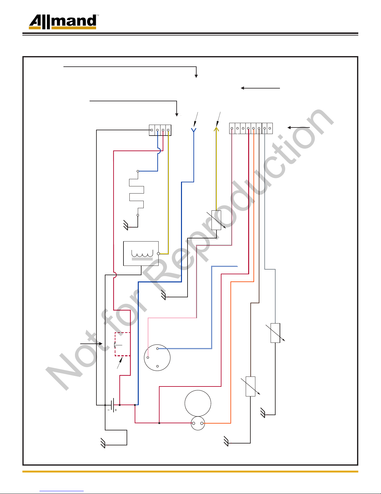
1.3 - CAT C1.1 Schematic
1.3
2
3
1
4
5
6
7
8
COOLANT TEMPERATURE
SWITCH (NO-CLOSES ON HIGH TEMP)
OIL PRESSURE SWITCH
(NC-OPENS ON
PRESSURE INCREASE)
STARTER
SOLENOID
B+
S
ALT
16AWG YELLOW
16AWG BLACK
FUEL LEVEL
SENDER
(OPTIONAL)
CONNECT TO
WIRE LABELED
"FUEL LEVEL"
(OPTIOANAL)
GLOW PLUGS
CONNECT TO
WIRE FROM
GLOW RELAY
8 PIN ENGINE HARNESS
CONNECTOR
4 PIN ENGINE HARNESS
CONNECTOR
PIN 1
PIN 2
PIN 4
PIN 3
OPTIONAL
WIRING
12AWG RED
E-STOP SWITCH
FUEL SOLENOID
12AWG RED
12AWG BLACK
ALTERNATOR
12AWG BLUE
14AWG YELLOW
16AWG GRAY
16AWG BROWN
16AWG ORANGE
14AWG RED
16AWG PINK
16AWG BLUE/WHITE
10AWG BLUE
16AWG BLACK
2AWG RED
2AWG BLACK
16AWG BLACK
16AWG BLACK
105888_A
(TO 1.1,
AND 1.4)
1st Connection
(TO 1.11)
2nd Connection
(TO 1.1)
3rd Connection
(TO 1.1)
4th Connection
Optional Connection
(TO 1.41)
Not for Reproduction
Allmand Product
Allmand Product Name Schematic Manual
©2016 Allmand™ Bros., Inc.
1.4 - CAT C1.1 Voltage Regulator Schematic
1.4
16AWG PINK
14AWG BLACK
14AWG RED
16AWG BLUE/WHITE
16AWG YELLOW
6 PIN VOLTAGE
REGULATOR
CONNECTOR
8 PIN ENGINE
HARNESS CONNECTOR
PIN 1
PIN 2
PIN 3
PIN 4
PIN 5
PIN 6
PIN 5
PIN 7
PIN 8
CONNECT TO WIRE
LABELED
"EG MODULE"
105899_A
(TO 1.3,
OR 1.5)
1st Connection
1st Connection
(TO 1.1,
OR 1.2)
Not for Reproduction
Allmand Product Name Schematic Manual
©2016 Allmand™ Bros., Inc.
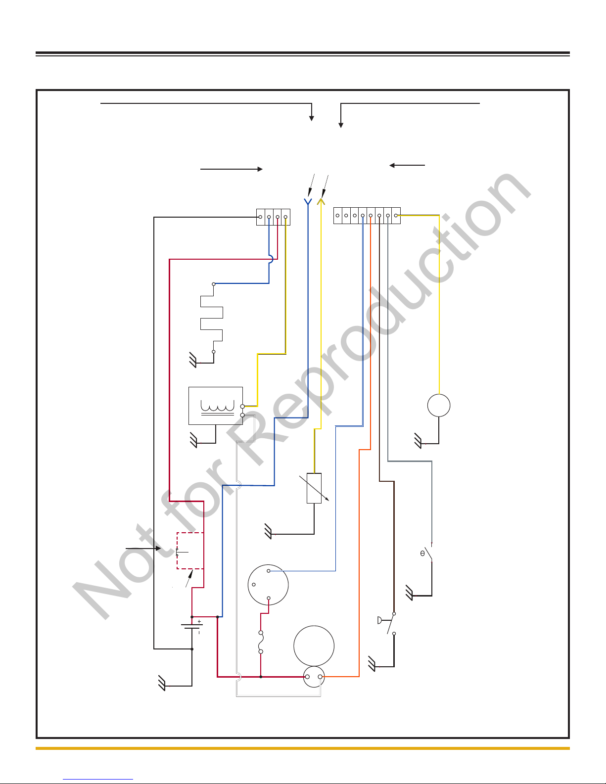
1.5 - CAT C1.1 LSC Schematic
1.5
2
3
1
4
5
6
7
8
COOLANT TEMP
SENDER
OIL PRESSURE
SENDER
STARTER
SOLENOID
B+
S
ALT
16AWG YELLOW
16AWG BLACK
FUEL LEVEL
SENDER
(OPTIONAL)
CONNECT TO
WIRE LABELED
"FUEL LEVEL"
(OPTIOANAL)
GLOW PLUGS
CONNECT TO
WIRE FROM
GLOW RELAY
8 PIN ENGINE HARNESS
CONNECTOR
4 PIN ENGINE HARNESS
CONNECTOR
PIN 1
PIN 2
PIN 4
PIN 3
OPTIONAL
WIRING
12AWG RED
E-STOP SWITCH
FUEL SOLENOID
12AWG RED
12AWG BLACK
ALTERNATOR
12AWG BLUE
14AWG YELLOW
16AWG GRAY
16AWG BROWN
16AWG ORANGE
14AWG RED
16AWG PINK
16AWG BLUE/WHITE
10AWG BLUE
16AWG BLACK
2AWG RED
2AWG BLACK
105904_A
(TO 1.2,
AND 1.4)
1st Connection
(TO 1.11)
2nd Connection
(TO 1.2)
3rd Connection
(TO 1.2)
4th Connection
Optional Connection
(TO 1.41)
Not for Reproduction
Allmand Product
Allmand Product Name Schematic Manual
©2016 Allmand™ Bros., Inc.
1.6 - Kubota D1005/1105 Schematic
1.6
COOLANT TEMP
SWITCH
OIL PRESSURE
SWITCH
STARTER
SOLENOID
B+
PIN 1
(IG)
FUEL SOLENOID
GLOW PLUGS
PIN 1 PIN 2
14AWG YELLOW
12AWG BLUE
14AWG YELLOW
10AWG RED
12AWG BLACK
14AWG WHITE
2 AWG BLACK
2AWG RED
16AWG BLUE W/WHITE
14AWG ORANGE
16AWG GRAY
16AWG BROWN
OPTIONAL
WIRING
10AWG RED
EMERGENCY
STOP SWITCH
FUEL PUMP
2
3
1
4
5
6
7
8
1
2
3
4
8 PIN ENGINE
HARNESS
CONNECTOR
4 PIN ENGINE
HARNESS
CONNECTOR
FUSE 30A
S
ALT
16AWG YELLOW
FUEL LEVEL
SENDER
(OPTIONAL)
CONNECT TO
WIRE LABELED
"FUEL LEVEL"
(OPTIOANAL)
CONNECT TO
WIRE FROM
GLOW RELAY
105893_A
(TO 1.1)
1st Connection
(TO 1.11)
2nd Connection
(TO 1.1)
3rd Connection
(TO 1.1)
4th Connection
Optional Connection
(TO 1.41)
Not for Reproduction

Allmand Product Name Schematic Manual
©2016 Allmand™ Bros., Inc.
1.7 - Kubota D1005/1105 LSC Schematic
1.7
COOLANT TEMP
SENDER
OIL PRESSURE
SENDER
STARTER
SOLENOID
B+
PIN 1
(IG)
FUEL SOLENOID
GLOW PLUGS
PIN 1 PIN 2
14AWG YELLOW
12AWG BLUE
14AWG YELLOW
12AWG RED
12AWG
BLACK
14AWG WHITE
2 AWG
BLACK
2AWG RED
16AWG BLUE W/WHITE
14AWG ORANGE
16AWG GRAY
16AWG BROWN
16AWG YELLOW
OPTIONAL
WIRING
12AWG RED
EMERGENCY
STOP SWITCH
FUEL PUMP
2
3
1
4
5
6
7
8
1
2
3
4
8 PIN ENGINE
HARNESS
CONNECTOR
4 PIN ENGINE
HARNESS
CONNECTOR
FUSE 30A
10AWG BLUE
16AWG BLACK
FUEL LEVEL
SENDER
(OPTIONAL)
CONNECT TO
WIRE LABELED
"FUEL LEVEL"
(OPTIOANAL)
CONNECT TO
GLOW RELAY
S
ALT
105905_A
(TO 1.2)
1st Connection
(TO 1.11)
2nd Connection
(TO 1.2)
3rd Connection
(TO 1.2)
4th Connection Optional Connection
(TO 1.41)
Not for Reproduction
Allmand Product
Allmand Product Name Schematic Manual
©2016 Allmand™ Bros., Inc.
1.8 - Shocker Valve Schematic
1.8
2 AWG RED
2 AWG
BLACK
2 AWG RED
REV LIMITER
5 PORT
LEVER
LOCK
2 PORT
DELPHI
CONNECTOR
3 PORT
DELPHI
CONNECTOR
VALVE SOLENOID
RPM SENSOR
20 AMP
AUTOMATIC
RESET
MANUAL KILL SWITCH
14 GA RED
14 GA BLACK
WHITE
BLACK
RED
WHITE
BLACK
PIN 1
PIN 2
PIN 3
PIN 4
PIN 5
PIN 6
PIN 7
PIN 8
PIN 9
PIN 10
14 GA ORANGE
14 GA YELLOW
14 GA PURPLE
14 GA WHITE
16 GA GREEN
16 GA
BLACK
14 GA BLACK
BATTERY
14 GA BLACK
STARTER
OPTIONAL
BATTERY
DISCONNECT
B+
14 GA RED
106156_A
Not for Reproduction
Allmand Product Name Schematic Manual
©2016 Allmand™ Bros., Inc.
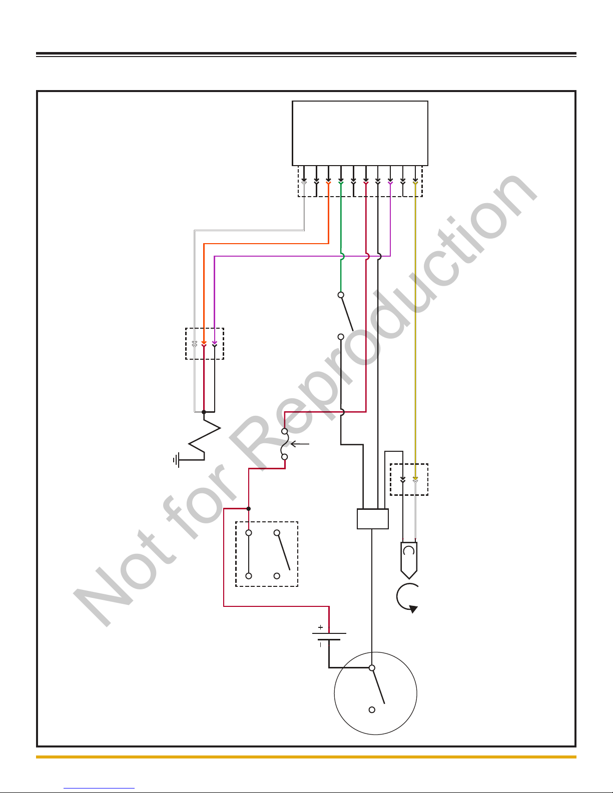
1.9 - Low Fuel Module Schematic
1.9
16AWG WHITE
16AWG GRAY
16AWG
ORANGE
16AWG
ORANGE
16AWG
YELLOW
16AWG RED
16AWG RED
16AWG BLACK
"ACC" RED
16AWG WHITE
LOW FUEL
BEACON (LED)
ENGINE CONTROLS
SLS
12VDC
GROUND
STUD
16AWG YELLOW
FUEL LEVEL SENDER
200 Ω
LOW FUEL MODULE
PIN 1
PIN 12
PIN 2
PIN 1
2 PIN
LEVER
LOCK
12 PIN DEUSTCH
2 PIN
DEUSTCH
CAN BUS
JUMPER
HARNESS
16AWG
BLACK
16AWG WHITE
16AWG BLACK
16AWG
WHITE
16AWG
GRAY
16AWG BLACK
105901_A
(TO 1.1)
3rd Connection
(TO 1.11)
1st Connection
(TO 1.10)
2nd Connection
Not for Reproduction
Allmand Product
Allmand Product Name Schematic Manual
©2016 Allmand™ Bros., Inc.
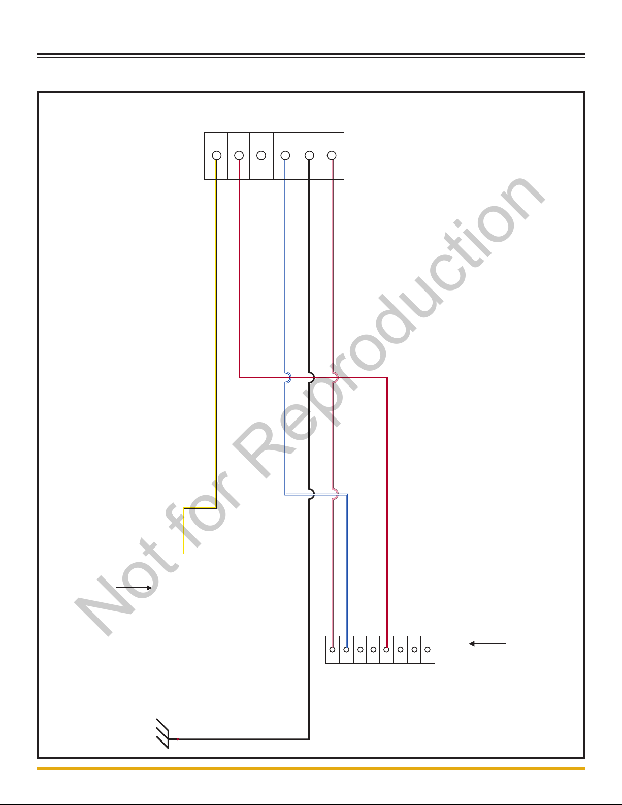
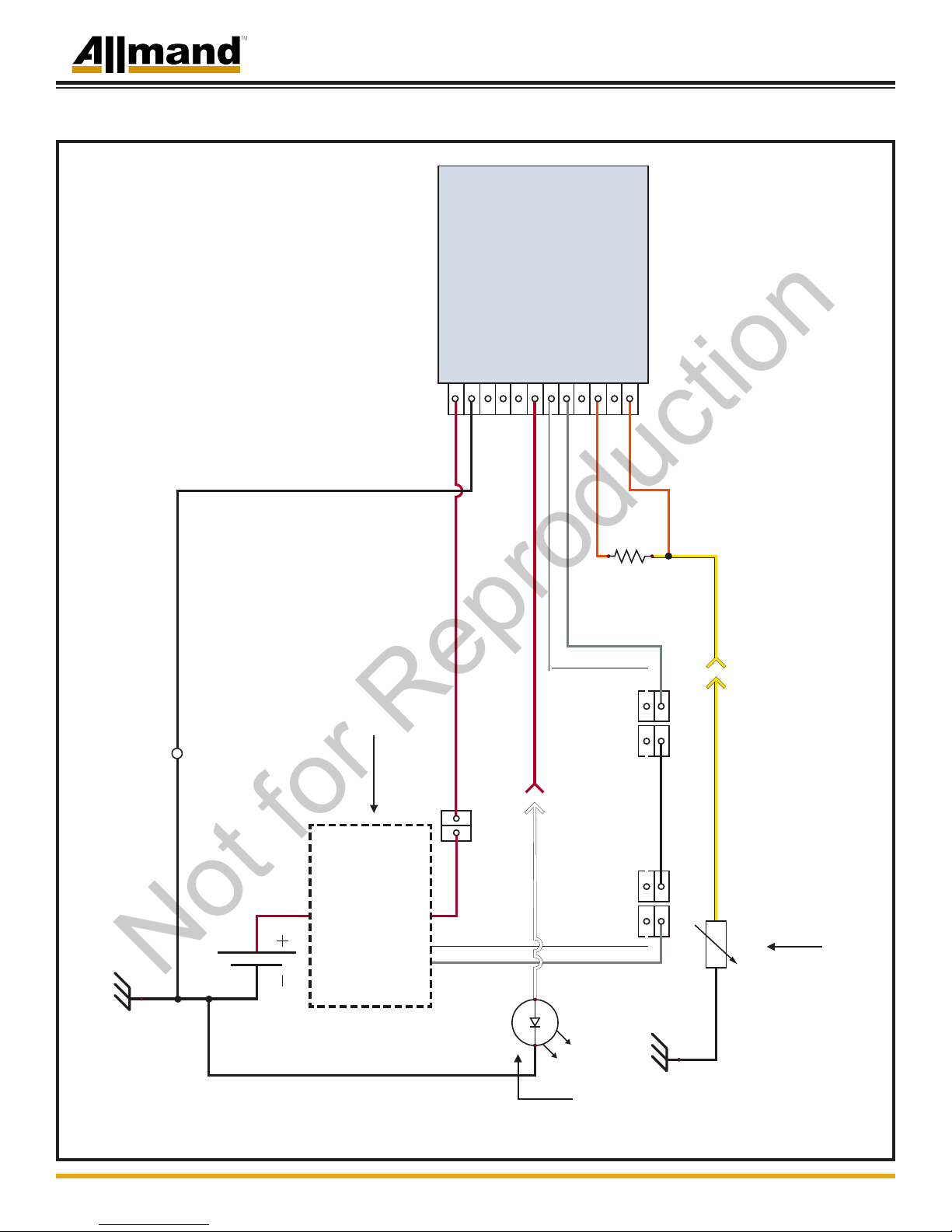
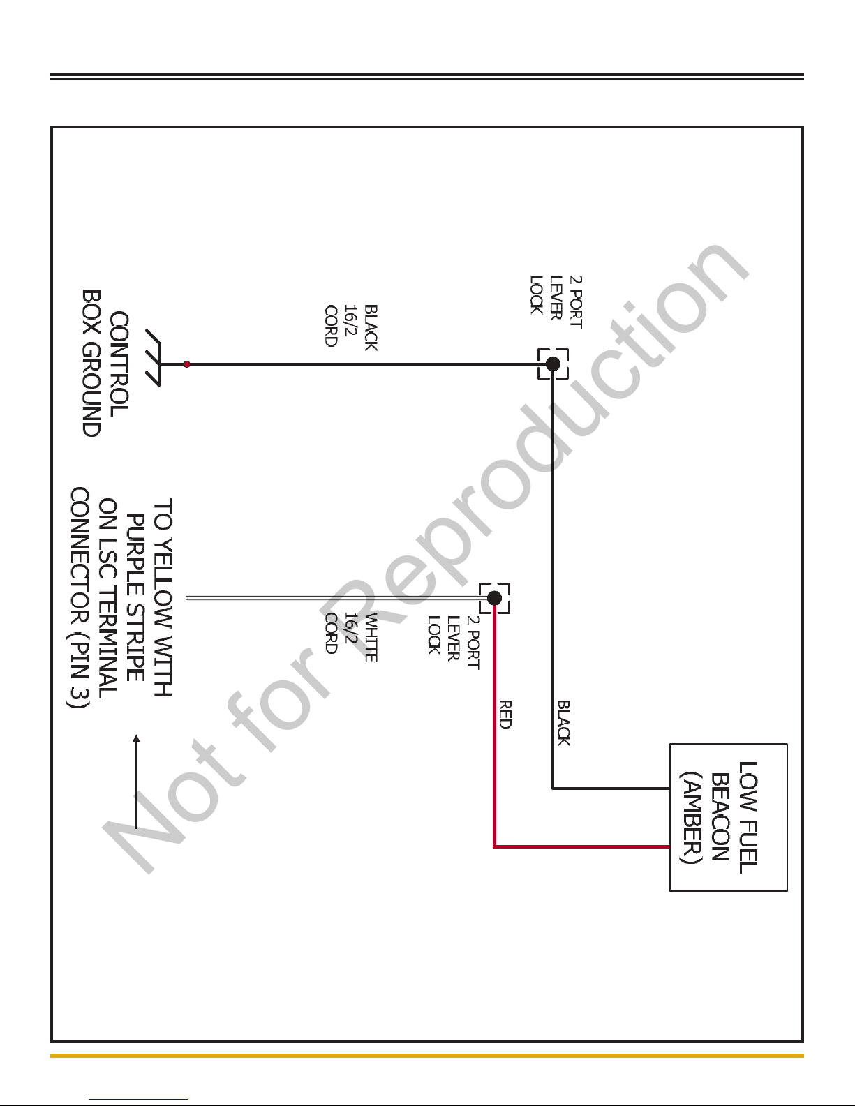
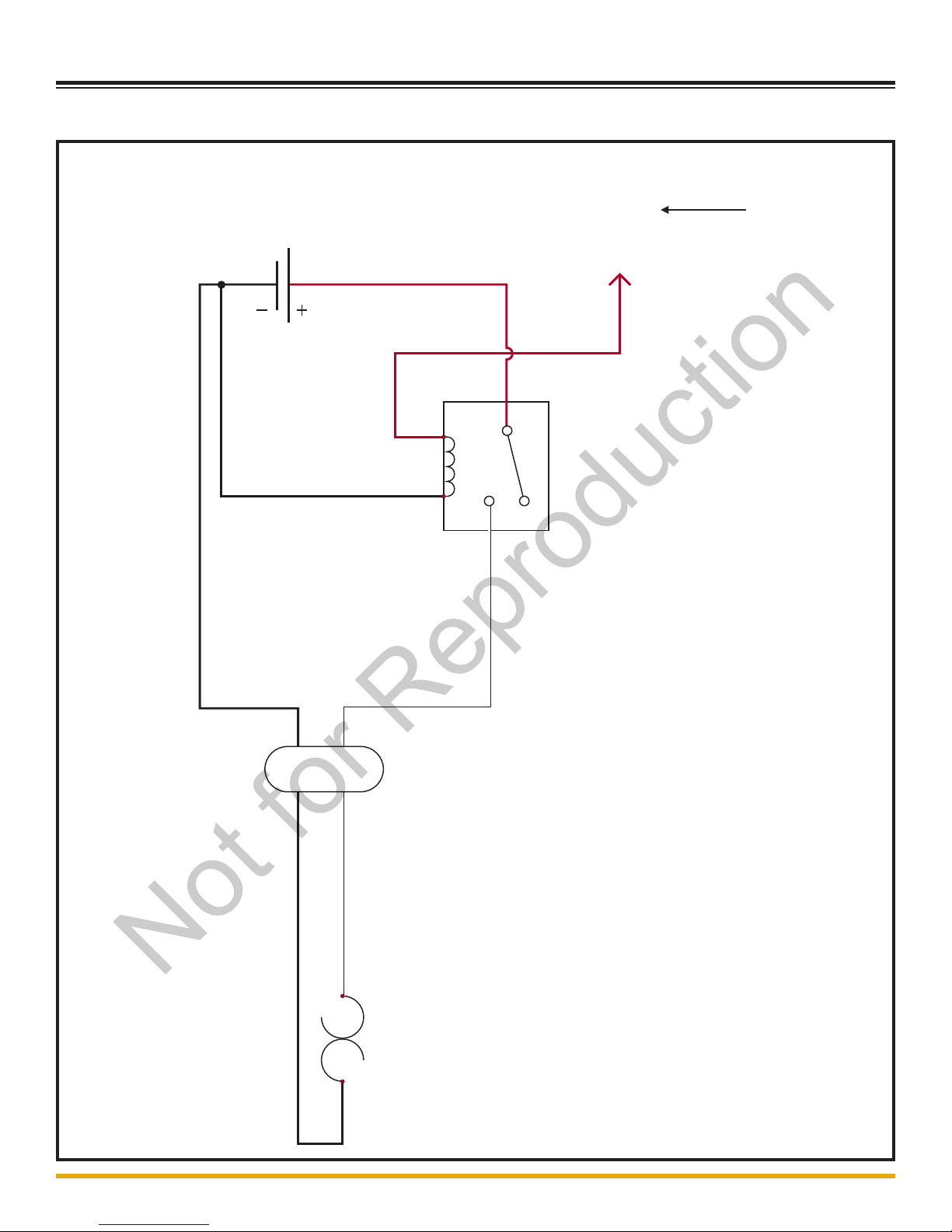
1.10 - Low Fuel Beacon Schematic
1.10
105897_A
(TO 1.2,
OR 1.9)
1st Connection
Not for Reproduction
Allmand Product Name Schematic Manual
©2016 Allmand™ Bros., Inc.
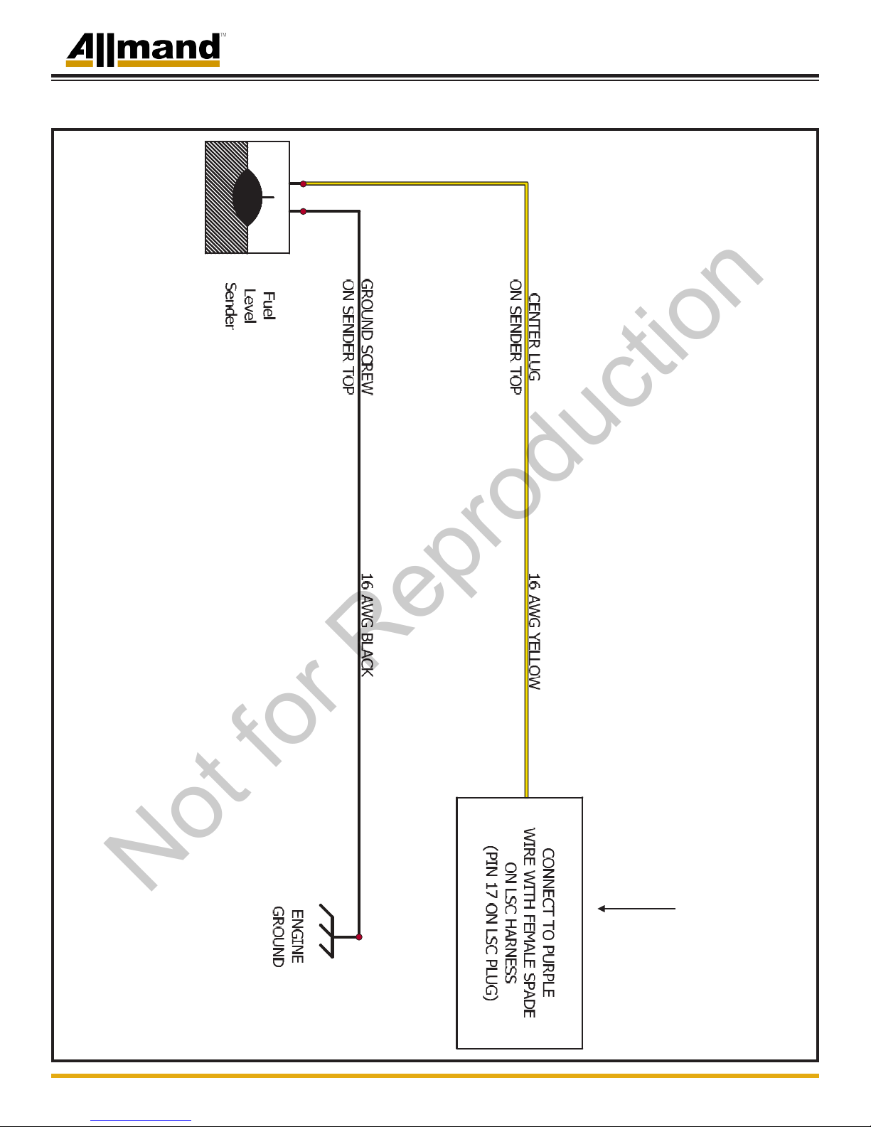
1.11 - Low Fuel Sender Schematic
1.11
106341_A
(TO 1.2, 1.3,
OR 1.6)
1st Connection
Not for Reproduction
Allmand Product
Allmand Product Name Schematic Manual
©2016 Allmand™ Bros., Inc.
1.12 - Heated Fuel/Water Separator Schematic
1.12
HEATED FUEL/WATER
SEPARATOR
14AWG BLACK
14AWG
RED
14AWG
RED
CONNECTS TO
"ACC" WIRE
ON SLS OR LSC
16-2 SOOW
CORD
WHITE
BLACK
30
87
86 85
105886_A
(TO 1.1,
OR 1.2)
1st Connection
Not for Reproduction

Allmand Product Name Schematic Manual
©2016 Allmand™ Bros., Inc.
1.13 - 4 Light 14/7 Cord Schematic
1.13
#3 BLACK #4 BLACK#1 BLACK
BLACK
RED W/ BLACK STRIPE
RED
BLUE
YELLOW
BROWN
ORANGE
#1 GREEN
#2 GREEN
#3 GREEN
#4 GREEN
#1 WHITE
#2 WHITE
#3 WHITE
#4 WHITE
JUNCTION BOX
#1 LAMP #2 LAMP #3 LAMP #4 LAMP
3 PORT
LEVER
LOCK
2 PORT
LEVER
LOCK
2 PORT
LEVER
LOCK
2 PORT
LEVER
LOCK
2 PORT
LEVER
LOCK
2 PORT
LEVER
LOCK
#2 BLACK
3 PORT
LEVER
LOCK
16 GA GREEN
16 GA
GREEN
6 PORT
PUSH-IN
CONNECTOR
105291_A
(TO 1.18, 1.19,
OR 1.20)
1st Connection
Not for Reproduction
Other manuals for NIGHT-LITE PRO II
4
Table of contents
Other Allmand Construction Equipment manuals


