Allstar J & H Series User manual

INSTALLATION AND
OWNER’S MANUAL
As of date of manufacture,
meets all ANSI/UL 325
Safety Requirements for
Vehicular door operators
J & H
J & H SERIES JACKSHAFT COMMERCIAL
VEHICULAR DOOR OPERATORS
READ THIS MANUAL
CAREFULLY BEFORE
INSTALLATION OR USE
SAVE THESE INSTRUCTIONS !
Serial #:
Date Installed:
Your Dealer:
READ THESE STATEMENTS CAREFULLY AND FOLLOW THE
INSTRUCTIONS CLOSELY.
The Warning and Caution boxes throughout this manual are there to protect you and
your equipment. Pay close attention to these boxes as you follow the manual.
WARNING
Indicates a MECHANICAL
hazard of INJURY OR
DEATH. Gives instructions
to avoid the hazard.
CAUTION
Indicates a MECHANICAL hazard
of DAMAGE to your operator or
equipment. Gives instructions to
avoid the hazard.
Indicates an ELECTRICAL
hazard of INJURY OR
DEATH. Gives instructions
to avoid the hazard.
WARNING
Indicates an ELECTRICAL hazard
of DAMAGE to your operator or
equipment. Gives instructions to
avoid the hazard.
CAUTION
TABLE OF CONTENTS
Jackshaft Operator Applications..................................................................................3
Preparation ....................................................................................................................4
Figure 1 - Component Identification Pictorial..............................................................4
Important Installation Warnings (Things To Do Before & During Installation) .........5
Table 1 - Component Identification Listing..................................................................5
Installation Instructions .............................................................................................6-7
Figure 2 - Operator Footprint - J/H ...............................................................................6
Figure 5 - Release/Hand Chain Wall Bracket Installation ...........................................7
Figure 6 - Mounting Positions ......................................................................................8
Figure 7 - Operator Dimensions - Model H ..................................................................9
Figure 7A - Operator Dimensions - Model J ................................................................9
Setting The Limits .......................................................................................................10
Figure 8 - Limit Adjustment ........................................................................................10
Electrical Wiring Instructions .....................................................................................11
Figure 9 - Pneumatic Door Edge Installation.............................................................12
Figure 10 - Field Wiring...............................................................................................12
Operation and Adjustment Instructions ...............................................................13-17
Important Safety Instructions for Owner ...................................................................13
Wiring Terms ...............................................................................................................13
Wiring Types................................................................................................................14
Clutch Adjustment.......................................................................................................15
Brake Adjustment........................................................................................................16
Testing .........................................................................................................................16
Maintenance ................................................................................................................17
Wiring Diagram - Single Phase...................................................................................18
Wiring Diagram - Three Phase....................................................................................19
Warranty.......................................................................................................................20
2

The purpose of this booklet is to provide assembly,
installation and operation information concerning Allstar
Model J & H Commercial Vehicular Garage Door
Operators and related Accessory Products.
NOTICE
IT IS IMPORTANT THAT THIS INSTRUCTION
MANUAL BE READ AND UNDERSTOOD
COMPLETELY BEFORE INSTALLATION OR
OPERATION IS ATTEMPTED. IT IS
INTENDED THAT THE INSTALLATION OF
THIS UNIT WILL BE DONE ONLY BY
PERSONS TRAINED AND QUALIFIED IN
THE INSTALLATION, ADJUSTMENT AND
SERVICE OF COMMERCIAL OVERHEAD
DOORS AND DOOR OPERATORS AND BY
QUALIFIED ELECTRICIANS.
NOTICE
THE IMPORTANT SAFEGUARDS AND
INSTRUCTIONS IN THIS MANUAL CANNOT
COVER ALL POSSIBLE CONDITIONS AND
SITUATIONS WHICH MAY OCCUR DURING
ITS USE. IT MUST BE UNDERSTOOD THAT
COMMON SENSE AND CAUTION MUST BE
EXERCISED BY THE PERSON(S) INSTAL-
LING, MAINTAINING AND OPERATING THE
EQUIPMENT DESCRIBED HEREIN. DO NOT
USE THIS EQUIPMENT FOR ANY OTHER
THAN ITS INTENDED
PURPOSE - OPERATING OVERHEAD
COMMERCIAL VEHICULAR GARAGE
DOORS.
STANDARD FEATURES:
Limit Switches: Driven limit switches, easily adjusted
over a wide range. The motor may be removed without
affecting the limit switch adjustments
Manual Release: Permits manual operation of the
door in the event of a power failure. The Model H is
equipped with a chain hoist to aid in manual operation.
Control Circuit: Standard three button open, close
and stop. 24 Volts AC.
Connections For Auxiliary Entrapment Protect-
ion Devices: Use with foam or pneumatic reversing
door edge components or a photoelectric beam (across
the opening) device.
Constant Contact To Close: Feature can be activat-
ed by simply moving a wire on the terminal strip.
Momentary Contact To Close: Standard operation.
MODEL J & H OPERATOR APPLICATIONS:
Jackshaft operators are intended for commercial and
industrial use to raise or lower sectional overhead
doors by chain coupling or direct coupling to the door
shaft. Jackshaft operators are suitable where all or
part of the door remains in a vertical position when
fully open such as doors with at least 18 inches of lift
clearance or full vertical lift doors. Jackshaft
operators may also be used with roll up service doors
and grills when appropriately modified at the factory
to obtain the correct speeds.
A jackhaft operator DOES NOT LOCK THE DOOR
IN ITS CLOSED POSITION. However, because the
cross-header shaft is prevented by the operator from
turning, the torsion springs provide no assistance in
lifting the door should an attempt be made to raise it
manually.
The J & H Series jackshaft operators are used in
the following applications:
- Continuous Duty, Medium Cycle Commercial
installations only
- Indoor Use Only
- Up to 24 foot high doors with a maximum area
of 480 square feet for 3/4 HP, 280 square feet
for 1/2 HP and 200 square feet for 1/3 HP -
maximum area slightly higher for lighter doors
- consult factory
- Use with foam/pneumatic reversing door edge
or photoelectric device - REQUIRED where the
3-button station is out of sight of the door, or
any other automatic, remote or manual control
is used to activate the door
OPTIONAL FEATURES:
Digital Radio Controls: Open, Close and Stop
operation. Radio units are available to control up to 27
doors from one transmitter
Digital Timer to Close: Adjustable from 0 to 17
minutes in one second intervals.
Keyless Entry System: Connection terminals
provided for hard wired or wireless keyless entry
systems.
PRODUCT FEATURES
3

Before starting the installation of the operator, the door must be in
good working condition and properly counterbalanced. Inspect the
door and track for loose or missing hardware. Test the door
manually for balance and ease of operation. Lubricate door hinges
and rollers. If necessary, employ a qualified technician to adjust the
springs for proper counterbalance of the door.
Stops should be installed at the top end of each track to prevent the
possibility of the door rollers moving beyond the ends of the track.
If the cross header shaft is made from hollow tubing rather than
solid rod, it is recommended that it be plugged with a short length of
solid bar for a more secure installation of the shaft sprocket or
flange coupler.
Before removing the operator powerhead from the shipping carton,
inspect the nameplate on the cover of the operator control box to
verify that it is the correct model for the intended
application and that the voltage and phase are in accordance
with electrical power provided at the job site. If the operator
was ordered with the optional chain hoist, Model H, see that it
is so equipped. A chain hoist CANNOT be added in the field.
Warning: Rope off the area to keep personnel and
vehicles clear of the door and floor space in the vicinity of
the operator during the installation.
ELECTRIC DOOR OPENERS ARE DESIGNED
FOR DOORS IN GOOD WORKING CONDITION,
PROPERLY COUNTERBALANCED AND
PROPERLY ADJUSTED IN ACCORDANCE
WITH THE DOOR MANUFACTURER'S
INSTALLATION INSTRUCTIONS.
WARNING
SPRINGS ARE SUBJECT TO VERY
HIGH FORCES AT ALL TIMES AND
ADJUSTMENTS MUST BE MADE
ONLY BY A QUALIFIED
PROFESSIONAL DOOR INSTALLER.
WARNING
REMOVE OR DISABLE ANY LOCKING
DEVICES FROM DOOR AND REMOVE
ALL ROPES
WARNING
PREPARATION
COMPONENT IDENTIFICATION
4
107170
TO REDUCE THE RISK OF SEVERE INJURY
OR DEATH: READ AND FOLLOW ALL
INSTALLATION INSTRUCTIONS!
WARNING
•Install only on a properly balanced garage
door. An improperly balanced door could
cause severe injury. Have a qualified service
person make repairs to cables, spring
assemblies and other hardware before
installing the opener.
• Remove all ropes and remove or make
inoperative all locks (unless mechanically and/
or electrically interlocked to the power unit)
that are connected to the garage door before
installing the opener.
• Lightweight doors (fiberglass, aluminum
etc.) must be reinforced to avoid door damage.
Check the door manufacturer’s instruction
manual for a bracing procedure or the
availability or a Reinforcement Kit.
• Allstar Models J and H are Commercial
Vehicular Door Operators and as such are
NOT recommended for pedestrian traffic. In
installations where it is known that
pedestrians will be nearby ensure a pedestrian
door is available for entrance and exit to the
building. In addition YOU MUST install an
auxiliary entrapment protection device
(reversing door edge or photoelectric beam
device) as part of the compete operator
system.
• Connect an auxiliary entrapment
protection device (reversing edge or
photoelectric device across the door opening).
A device of this type is STRONGLY
ADVISED FOR ALL commercial operator
installations. An auxiliary entrapment
protection device is REQUIRED when the
three button control station is out of sight of
the door or any other automatic or manual
control is used.
• Install the opener at least 8 feet or more
above the floor.
• Do not connect the opener to the source
of power until instructed to do so.
• Locate the control station:
a) within sight of the door and;
b) at a minimum height of five feet
above the floor and;
c) away from all moving parts of the
door.
• Do not overtighten the clutch adjustment
to compensate for a poorly working door.
• Securely attach any WARNING signs or
placards to either the door or above the
control station as directed (see page 11).
• After installing the opener, all safety
features must be tested for proper operation
(see page 16).
COMPONENT IDENTIFICATION LISTING
ITEM PART # DESCRIPTION QTY ITEM PART # DESCRIPTION QTY
1 Per Model Operator Power Head 1 8 009149 Release Chain AR
2 005031 3 Button St ation 1 9 100315 #3 Hand Chain - Precut to 26 FT AR
3 105270 24 Tooth, #50 Chain Sprocket (Standard) 1 10 105349 #50 Drive Chain - 6 FT Long 1
4 105268 12 Tooth, #50 Chain Sprocket (Standard) 1 11 105351 #50 Chain Connecting Link 1
5 105193 Release/Hand Chain Wall Bracket 1
6 100413 1/4” Square Key 2 AR - AS REQUIRED
7 006119 5/16-18 x 1 Square Head Set Screw 4
IMPORTANT INSTALLATION NOTES
5

SPRINGS, PULLEYS, CABLES AND MOUNTING HARDWARE USED TO
BALANCE YOUR GARAGE DOOR ARE UNDER EXTREME TENSION AT ALL
TIMES AND CAN CAUSE SEVERE INJURY OR DEATH IF DISTURBED.
DO NOT ATTEMPT ADJUSTMENT.
Figure 6, page 8 illustrates several positions suitable for
mounting the operator; right hand or left hand, either wall mount
or ceiling mount.
CHAIN COUPLING MOUNTING
Refer to Figure 2 (at right), Figure 1, page 4 and Figure 7, page
9 for component identification and the operator mounting slot
locations. Place the sprockets [ 5 ] and [ 14 ] on the chosen side
of the torsion shaft of the door and on the corresponding end of
the output shaft of the operator, see Figure 3. The sprockets
should be kept as close as possible to the bearings. Fasten the
connecting link to each end of the door chain and loop the chain
over the sprocket [ 5 ] on the torsion shaft. Temporarily suspend
the operator in its mounting position using the chain over the
sprocket [ 14 ] at one end of the jackshaft and a rope or chain at
the mid point (to support the operator weight). With the chain
tight and straight and the jackshaft parallel with the torsion shaft,
trace the mounting slot on the mounting surface then lower the
operator to the floor.
IT IS ESSENTIAL THAT THE SURFACE
SUPPORTING THE OPERATOR BE RIGID
AND SECURE. FAILURE TO PROVIDE A FIRM
MOUNTING SURFACE WILL RESULT IN
DAMAGE TO THE DOOR TORSION SHAFT
AND THE PREMATURE FAILURE OF THE
OPERATOR.
If the construction permits, the operator should be mounted with
3/8 inch diameter bolts through the wall. If it is not feasible to go
through the wall, then use lag bolts to fasten the operator to the
mounting surface. Locate the four holes within the tracings of the
slots made in the previous step at the positions which will allow
for adjust-ment of the chain tension. After drilling the mounting
holes and instal-ling lag shields, if necessary, bolt the operator to
the mounting surface but do not completely tighten the bolts at
this time. Check the alignment of the sprockets, adjust their
positions on the shafts if necessary and tighten the set screws
securely on both sprockets. pulling downward on the operator to
remove slack from the chain, tighten the four mounting bolts.
Inspect the installation. There should be no slack in the chain but
neither should it be under severe tension which might shorten the
life of the bearings. If there is any flexibility in the system due
to construction of the surface supporting the operator or
noticeable deflection of the door shaft, it is advisable to install a
shaft support between the operator jackshaft and the door shaft
to prevent the loss of limit settings due to the possibility of the
chain jumping over the sprocket teeth. Shaft supports are
available from the factory.
If there isn’t a keyway on the doorshaft, keep the sprockets
aligned and drill a 5/16” hole through the door drive sprockets
and door shaft. Insert roll pin, Item (2). See Figures 3 & 4.
BEFORE PROCEEDING WITH THE
OPERATOR INSTALLATION AND SETTINGS,
MAKE A FINAL CHECK FOR TIGHTNESS OF
ALL MOUNTING HARDWARE AND SET
SCREWS.
Proceed to “Chain Hoist and Floor Disconnect Installation”.
WARNING
INSTALLATION INSTRUCTIONS 6
107851
Figure 2

Figure 5
CHAIN HOIST AND FLOOR DISCONNECT
INSTALLATION
If the operator is furnished with a chain hoist (Model H), pass the
hand chain over the chain wheel and through the chain guides on
the operator clutch shaft (opposite end from the large pulley).
Fasten the ends of the chain together by opening and re-closing one
link using two pairs of pliers. If the chain is too long (standard
length for 16 foot high doors and below is 26 feet total length of
chain), shorten it to the desired length using the method described
above and discard the unused portion.
Fasten the chain hoist holding bracket furnished with the operator
to the wall approximately four feet from the floor. This bracket is
also used to hold in place the release chain for both the chain hoist
equipped units (Model H) and floor disconnect models (Model J).
INSTALLATION INSTRUCTIONS
Figure 3
Figure 4
107613
7
107174
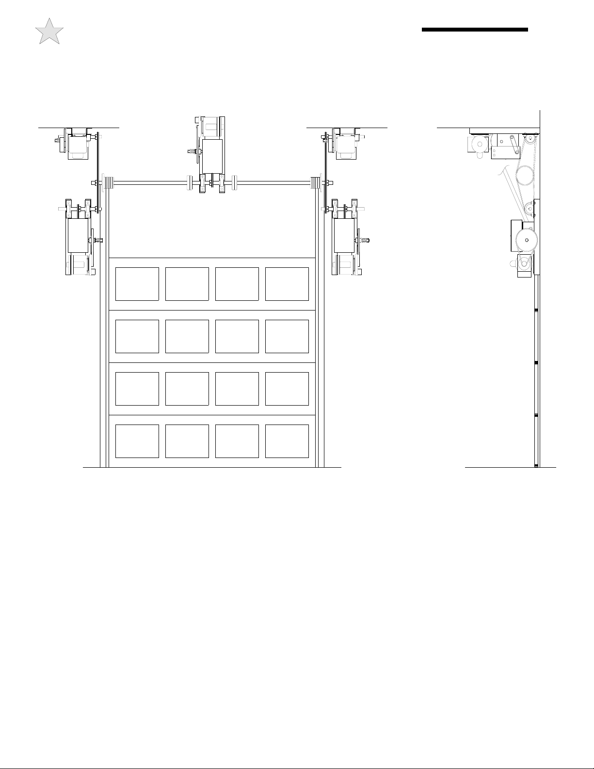
Figure 6
100719
Right Side
Mount
Ceiling
Mount
Left Side
Mount
Ceiling
Mount
Center
Mount
Direct
Couple
Wall
Mount
Wall
Mount
FIGURE 6 - OPERATOR MOUNTING POSITIONS 8

FIGURE 7 and 7A- OPERATOR DIMENSIONS
9
107841
Figure 7A - Dimensions Model J
Figure 7 - Dimensions Model H
108203
TO AVOID RISK OF ENTRAPMENT AND
POSSIBLE DAMAGE TO THE DOOR AND
OPERATOR THE LIMITS MUST BE ADJUSTED
BEFORE APPLYING POWER TO THE
OPERATOR.
WARNING
INSTALLATION INSTRUCTIONS 10
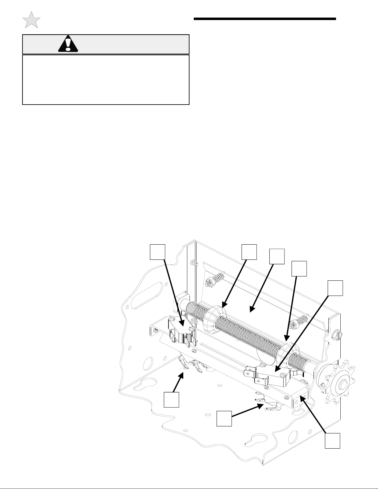
SETTING THE LIMIT SWITCHES
1) With the cover open on the electrical enclosure, reference
Figure 8 below. There are four (4) switches (A, B, C, and D)
mounted to the ‘V’ bracket (H). The limit switches are mounted
in a fixed position to the underside of the ‘V’ bracket; with the
Close Limit switch (B) on the right and the Open Limit switch (D)
on the left. The Reverse Cutout switch (A) and the Single Button
Selector switch (C, also could be Timer Engage switch depending
on the model) are mounted to the top side of the ‘V’ bracket as
shown. The switches are activated by the two limit nuts (E & G)
on the threaded shaft which move laterally along the shaft as the
operator opens and closes the door. When a limit nut nears the
end of the shaft it activates a set of switches, upper switch first
then the lower fixed limit switch.
2) Depress the Limit Nut Retention Plate (F) so it disengages
from the slots in the limit nuts and move the Limit nuts to the
center of the threaded shaft.
3) Manually raise the door to a nearly open position.
4) Depress the limit nut retaining bracket (F) so it disengages
from the slots in the limit nuts. Turn the OPEN limit nut (E) on
the shaft until it engages both the Single Button Selector switch
(C) and the Open Limit Switch (D). You will need to listen for
two audible clicks. Release the retaining bracket and be sure
that it engages in slots of both limit nuts.
5) Manually lower the door to the fully closed position and
repeat Step #3 with the Close Limit nut (G) and Reverse Cutout
switch (A) and the Close Limit switch (B).
6) Manually move the door to a half open position. With the
door in a mid position there will be time to stop the door if
something or someone were in the door path when initially
starting the door.
7) A final limit adjustment will be necessary after the
connection of the power supply in order to ensure the door stops
at the proper Open and Close positions.
8) Adjustment of the Reverse Cutout switch (A) or Single
Button Selector switch (C) is done at the factory and should not
be needed in the field. Moving the Reverse Cutout switch
closer to the center of the box will increase the point where the
reversing feature cuts out (to allow for irregularity in the floor,
etc.). The reverse cutout point is factory adjusted to approx. 4
inches off the floor.
107102
Figure 8
Limit Assembly
A
B
C E
G
F
D
H
A - REVERSE CUTOUT SWITCH
(LS4, ADJUSTABLE)
B - CLOSE LIMIT SWITCH
(LS2, FIXED POSITION)
C - SINGLE BUTTON SELECTOR
or TIMER ENGAGE SWITCH
(LS3, ADJUSTABLE)
D - OPEN LIMIT SWITCH
(LS1, FIXED POSITION)
E - OPEN LIMIT NUT
F - LIMIT NUT RETAINING BRCKT
G - CLOSE LIMIT NUT
H - “V” BRACKET

TO AVOID DAMAGE TO DOOR AND
OPERATOR ENSURE ALL DOOR LOCKS ARE
DISABLED.
USE AN INTERLOCK SWITCH IF A LOCK IS
REQUIRED TO RETAIN FUNCTIONALTY.
CAUTION
RISK OF ENTRAPMENT THAT MAY
RESULT IN SERIOUS PERSONAL INJURY OR
DEATH. DISCONNECT POWER TO THE
OPENER BEFORE AND DURING
INSTALLATION OF AN ACCESSORY
REVERSING DOOR EDGE OR
PHOTOELECTRIC DEVICE. DO NOT
RECONNECT POWER TO OPENER UNTIL
INSTRUCTED TO DO SO. ENSURE DOORWAY
IS CLEAR BEFORE STARTING TESTING OF
UNIT.
WARNING
TO PREVENT THE RISK OF PERSONAL INJURY
AND/OR DAMAGE TO DOOR OR PROPERTY,
ONLY OPERATE DOOR CONTROL WHEN
DOOR IS IN CLEAR VIEW. IF CONTROL
STATION CANNOT BE LOCATED WHERE THE
DOOR IS VISIBLE OR IF ANY OTHER DEVICE IS
USED TO CONTROL THE DOOR AN AUXILIARY
ENTRAPMENT DEVICE (DOOR EDGE OR
PHOTOELECTRIC) MUST BE CONNECTED.
WARNING
TO PREVENT THE RISK OF PERSONAL INJURY
OR DEATH :
• DISCONNECT POWER AT THE FUSE BOX
BEFORE PROCEEDING.
• ELECTRICAL CONNECTIONS MUST BE MADE
BY A QUALIFIED INDIVIDUAL.
• OBSERVE LOCAL ELECTRICAL CODES WHEN
WIRING THE OPERATOR.
WARNING
WARNING: Allstar's J & H Series operators have been
designed and constructed for use with voltages from 115 Volts
AC to 480 Volts AC, in single or three phase. Check the
operator nameplate label on the control box cover for the
proper voltage and phase. The application of an improper
input voltage or phase will result in catastrophic failure to the
internal electrical components.
Observe local electrical codes when wiring the operator.
When hard wiring, observe state and local electrical codes. A
wiring diagram is attached to the inside of the control box cover.
Connect the appropriate voltage and phase power leads to the
appropriate terminals as per the wiring diagram and connect a
ground wire to the grounding screw. On three phase units,
incorrect phasing of the power supply will cause the motor to
rotate in the wrong direction (open when CLOSE button is pushed
and vice versa). To correct this, interchange any two of the
incoming three phase conductors.
The wiring diagram attached inside the cover of the control box
details all of the field wiring terminal connections for the operator.
Always connect the wires to the push-button controls and auxiliary
devices exactly as shown.
Warning: Control voltage of the operator is 24 volts AC,
Class 2. Do not run the power leads and control circuit wiring
in the same electrical conduit.
Note: Most J & H Series model operators are pre-wired for
door reversing edge components. To comply with code
requirements, the door reversing edge components must be
installed and wired to the operator. Refer to Figure 9 and 10
for Edge component wiring and installation.
For operator models not equipped with reversing edge
components ONLY ONE THREE BUTTON WALL
STATION AND NO OTHER MEANS OF CONTROL may
be used to control the operator. This is to comply with safety
requirements. In this case the pushbutton station must be located
WITHIN CLEAR SIGHT OF THE DOOR adjacent to a
placard (supplied with the operator) with this wording:
WARNING
TO PREVENT ENTRAPMENT
DO NOT START DOOR DOWNWARD
UNLESS DOOR WAY IS CLEAR
Operators which are equipped with a reversing edge circuit may
have one or more additional means of control which should be
wired in accordance with the diagram supplied in the operator.
To add a second three button station, refer to Figure 10.
Number 18 gauge wire or heavier must be used for wiring
the control stations and auxiliary control devices to the
operator. Smaller gauge wire will cause operational
problems, especially when multiple push-button stations are
used or during summer months.
ELECTRICAL WIRING INSTRUCTIONS
11
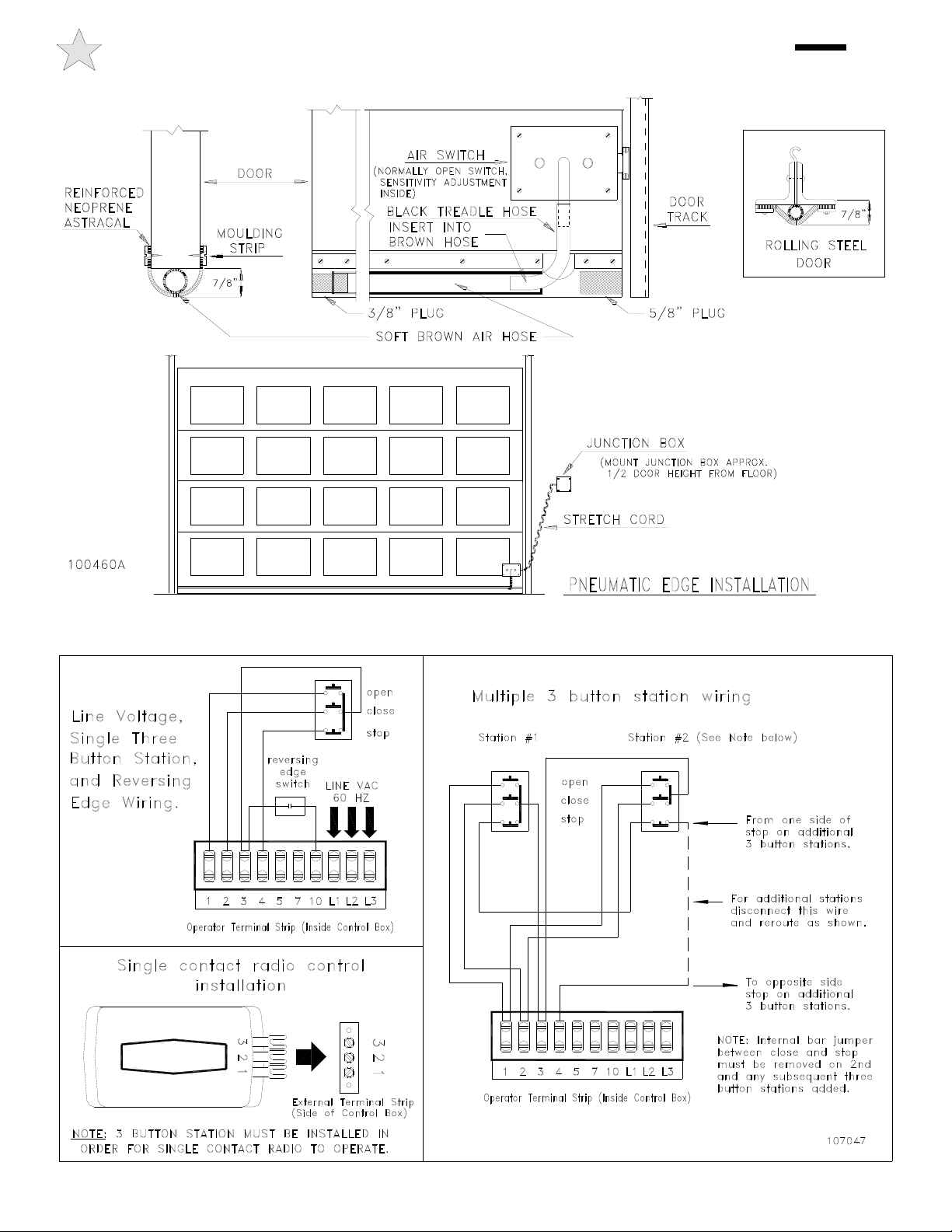
Figure 9
PNEUMATIC DOOR EDGE INSTALLATION - FIELD WIRING 12
Figure 10
OPERATION & ADJUSTMENT INSTRUCTIONS
NOTE: It is now necessary to turn on the power
in order to run the Opener to check for proper
operation and limit settings. Before doing so, ensure
that all mounting hardware are installed and properly
tightened, that all electrical connections are per local code
requirements, and that proper wiring practices have been
followed. Also, double-check that all ropes have
been removed from the door and that the doorway
is clear.
IMPORTANT SAFETY INSTRUCTIONS FOR OWNER
• NEVER let children operate or play with door controls. Keep the Remote Control away from
children.
• ALWAYS keep a moving door in sight and keep people and objects away from the door area
until the door is completely closed. NO ONE SHOULD CROSS THE PATH OF A MOVING
DOOR.
• TEST THE DOOR OPENER’S REVERSING FEATURE (where applicable) MONTHLY. The
door MUST reverse upon contact with a 4” high object on the floor. After adjusting the
force setting (clutch) or the limit of travel, ALWAYS RETEST the Opener. Failure to ADJUST
THE OPENER PROPERLY may result in SERIOUS INJURY OR DEATH.
• DO NOT over adjust the force setting (clutch) to compensate for a poorly working door. See
page 16 for procedure to check the door operation and page 14 for proper clutch
adjustment.
• If possible, USE THE MANUAL RELEASE only when the door is closed. Use caution when
using the Release with the door open. WEAK OR BROKEN SPRINGS MAY ALLOW THE
DOOR TO CLOSE RAPIDLY, CAUSING SEVERE INJURY OR DEATH.
• KEEP THE GARAGE DOOR PROPERLY BALANCED. See the door owner's manual. An
improperly balanced door MAY CAUSE SEVERE INJURY OR DEATH. Have a QUALIFIED
SERVICE PERSON MAKE REPAIRS TO CABLES, SPRING ASSEMBLIES AND OTHER
HARDWARE.
• SAVE THIS INSTRUCTION MANUAL FOR END USER.
TO REDUCE THE RISK OF SEVERE INJURY OR
DEATH: READ AND FOLLOW ALL INSTRUCTIONS!
WARNING
FAILURE TO TEST REVERSING SYSTEM
COULD RESULT IN DEATH OR SERIOUS
INJURY. TEST THIS SYSTEM ONCE A MONTH.
WARNING
MOMENTARY CONTACT: Button can be pushed and then
released and door will keep moving or stop without maintaining
pressure on the button.
CONSTANT PRESSURE: Constant pressure is required on the
button in order for continued door movement. When the button is
released the door will stop and possibly reverse to full open
depending on wiring type.
DOOR EDGE/PHOTOELECTRIC INPUT: The operator
wiring provides for input from an optional pneumatic or electric
door bottom edge or photoelectric device that will cause a closing
door to stop and may reverse it to open depending on the wiring
type.
OPEN OVERRIDE: When the door is closing a momentary
push of the OPEN button will reverse the door to open.
WIRING TERMS
AVOID ELECTROCUTION:
DO NOT ROUTE LOW VOLTAGE WIRES IN
SAME CONDUIT AS HIGH VOLTAGE
WIRES. FOLLOW ALL LOCAL
ELECTRICAL CODES OR THE NATIONAL
ELECTRICAL CODE (NEC).
WARNING
13

NOTE:Check the marking on the operator outer carton and the
wiring diagram on the inside control box cover for the wiring
type.
B WIRING
To Open - Momentary Contact
To Close - Momentary Contact
To Stop- Momentary Contact
B1 WIRING
To Open - Momentary Contact
To Close - Momentary Contact
To Stop- Momentary Contact
Door Edge/Photoelectric Input will stop the door when closing.
B2 WIRING
To Open - Momentary Contact
To Close - Momentary Contact
To Stop- Momentary Contact
Open Override- Standard
Door Edge/Photoelectric Input will reverse a closing door to
full open - door can be stopped with the STOP button at all times.
C WIRING
To Open - Momentary Contact
To Close - Constant Pressure:
Door will stop if pressure is released from CLOSE button
To Stop- Momentary Contact
C1 WIRING
To Open - Momentary Contact
To Close - Constant Pressure:
Door will stop if pressure is released from CLOSE button
To Stop- Momentary Contact
Door Edge/Photoelectric Input will stop the door when closing.
D WIRING
To Open - Momentary Contact
To Close - Constant Pressure
To Stop- Door will stop if pressure is released or when the
opener activates a limit switch at full open or full closed.
E WIRING
To Open - Momentary Contact
To Close - Constant Pressure:
If pressure is released door will reverse to full open
To Stop- Door will stop when the opener activates a limit switch
at full open or full closed. Door cannot be stopped in mid
travel.
E2 WIRING
To Open - Momentary Contact
To Close - Constant Pressure:
If pressure is released door will reverse to full open
To Stop- Door will stop when the opener activates a limit switch
at full open or full closed. Door cannot be stopped in mid
travel.
Door Edge/Photoelectric Input will reverse a closing door to
full open and door cannot be stopped.
R2 WIRING
To Open - Momentary Contact
To Close - Momentary Contact
To Stop- Momentary Contact
Open Override- Standard
Optional Single Button Radio Control Input will open or close
door but will not stop the door.
T1 WIRING
To Open - Momentary Contact
To Close - Momentary Contact
To Stop- Momentary Contact
Open Override- Standard
Door Edge/Photoelectric Input will reverse a closing door to
full open - door can be stopped with the STOP button at all
times..
Optional Adjustable Timer closes the door automatically. Time
interval resets when open button, open override, door edge or
auxiliary control is activated.
Optional Defeat Switch locks out timer when not required.
T2 WIRING
To Open - Momentary Contact
To Close - Momentary Contact
To Stop- Momentary Contact
Door Edge/Photoelectric Input will reverse a closing door to
full open - door can be stopped with the STOP button at all
times..
Optional Adjustable Timer closes the door automatically. Time
interval resets when door edge or auxiliary control is activated.
OPEN button will not start or reset timer.
Optional Defeat Switch locks out timer when not required.
WIRING TYPES 14

CLUTCH ADJUSTMENT
The clutch serves to protect the door, the electric operator and
other equipment from undue stress or damage caused by starting
forces and/or an obstruction to the door. It should be set no
tighter than is necessary to smoothly and consistently move the
door throughout its full range of travel. When properly set, it will
slip freely if the door should encounter an obstruction, and it
should be possible to stop the travel of the door by hand.
WARNING: Before adjustment remove power to the
operator.
To adjust the clutch, loosen the jamb nut, and turn the adjusting
nut, as shown at right Make adjustments in 1/4 turn increments.
Always re-tighten the jamb nut before running the operator to
prevent clutch from changing its setting.
CAUTION
NEVER COMPRESS CLUTCH SPRING BEYOND
POINT LIMITED BY THE DESIGN OF THE
OPERATOR OR REPLACE IT WITH A
HEAVIER SPRING
Due to changing conditions of the door and normal wear, it may
be necessary to occasionally readjust the clutch to obtain
dependable operation.
WARNING: BEFORE DOING SO BE CERTAIN THAT
THE DOOR IS IN GOOD WORKING CONDITION,
PROPERLY COUNTERBALANCED AND THAT THE
CLUTCH IS NOT SLIPPING BECAUSE OF LOOSE OR
MISSING HARDWARE, BINDING IN THE TRACK,
RUBBING AGAINST THE DOOR STOPS OR DEFECTIVE
OR MISADJUSTED SPRINGS. ANY SERVICE
REQUIRED TO THE DOOR, DOOR SPRINGS OR DOOR
OPERATOR MUST BE PREFORMED BY A QUALIFIED
PROFESSIONAL DOOR INSTALLER.
The clutch pad will wear during normal operation and should be
replaced when it becomes difficult or impossible to sufficiently
tighten the clutch to obtain smooth operation of the door when it
is in good working condition. To replace the clutch pad, first
loosen the motor mounting bolts and remove the V-belt then the
clutch adjusting nuts, spring and clutch pulley. Check condition
of V-belt before reassembly and replace if required. After
reassembly, adjust clutch as described above.
IMPROPER ADJUSTMENT OF CLUTCH
SETTING COULD CAUSE ENTRAPMENT,
INJURY OR DEATH.
SET CLUTCH ADJUSTMENT FOR JUST
ENOUGH FORCE TO OPERATE THE DOOR
RELIABLY, BUT NO STRONGER. Contact a
service professional to correct any binding,
sticking or other door problems. DO NOT
OVER-ADJUST CLUTCH SETTING TO
COMPENSATE FOR A POORLY WORKING
DOOR.
WARNING
OPERATION & ADJUSTMENT INSTRUCTIONS
RISK OF ENTRAPMENT THAT MAY RESULT
IN SERIOUS PERSONAL INJURY OR DEATH.
DISCONNECT POWER TO THE OPENER
BEFORE SERVICING OR MAKING
ADJUSTMENTS. ENSURE DOORWAY IS
CLEAR BEFORE STARTING TESTING OF UNIT.
WARNING
ALWAYS DISCONNECT POWER TO
OPERATOR BEFORE SERVICING OR MAKING
ADJUSTMENTS
CAUTION
15
Figure 11
107101

The solenoid operated brake may require occasional
adjustment. Adjustment is necessary if door tends to drift
downward after reaching the open limit. Follow the
instructions below and use Figure 12 as a guide.
(1) Loosen shoe adjusting screw and bottom bracket arm
of solenoid.
(2) Move tab until drum has a slight drag.
(3) Reverse drag slightly from tab and tighten shoe
adjustment screw.
Following installation, the operator MUST be tested and
respond correctly to all controls as specified on the wiring
diagram. KEEP personnel and equipment clear of the area
beneath the door when performing the tests. When testing the
3-button wall station, first observe that each button operates the
door in the direction indicated and that the STOP button
performs that function. With the door stopped at its full open
position, the OPEN button should be inoperative. This should
be verified and, likewise, the CLOSE button should be
inoperative with the door fully closed.
Certain operator control circuits use only a single button or a
two button control station and may be designed to function
differently than the more common three-button circuit
described above. Test the controls in accordance with the
description of operation as indicated on the wiring diagram and
on page 14, Wiring Types.
Observe the door when traveling in each direction for
smoothness of operation. Test the setting of the clutch by
restraining the door by hand. The clutch should slip. Re-check
the limit settings. The door should close tightly at the floor
without excessive impact. Likewise, it should fully clear the
door opening without the carrier striking the stops on the rail.
The J & H series operators are equipped with a reversing edge
circuit and to conform with code need to be connected to a
pneumatic edge or foam edge door components. To test it for
proper reversal, place an object beneath the leading edge of the
door. The door should instantly reverse when it comes into
contact with the object provided the height of the object
exceeds the cut out point built into the close limit switch
(approximately four inches).
BRAKE ADJUSTMENT
TESTING
CAUTION
DO NOT STAND UNDER DOOR
TO TEST REVERSING EDGE
USE A CORRUGATED BOX
OR OTHER SIMILAR OBJECT
If the operator is equipped with other means of control, such as
additional 3 button stations or radio controls, each of these
should be tested separately for proper operation.
To test the manual disconnect first move the door to the fully
closed position. Then disconnect the power to the operator.
Manual door operation mode should engage when the release
chain is pulled. The door can then be manually opened or
closed by physically moving the door (Model J) or using the
hoist chain (Model H). If it is difficult to engage and/or the
jackshaft to doorshaft chain appears to be under compression,
reset the CLOSE limit slightly to reduce the door travel in the
close direction.
ALWAYS DISCONNECT POWER TO
THE OPERATOR BEFORE SERVICING,
CONNECTING ACCESSORY DEVICES
OR MAKING ADJUSTMENTS.
WARNING
OPERATION AND ADJUSTMENT INSTRUCTIONS 16
107103
Figure 12

Normally, very little maintenance is required. A monthly visual
inspection must be made for loose or missing hardware and for
excessive slack in the V-Belt and jackshaft chain. The clutch
must be tested periodically and adjustments made if necessary
(see page 15). The brake is adjusted at the factory and will need
periodic adjustment for wear. When adjustment becomes
necessary see Figure 12 on page 16 for the adjustment
procedure.
Test the reversing edge circuit at least once a month by
permitting the door to contact an obstruction while closing.
CAUTION
DO NOT STAND UNDER DOOR TO TEST REVERSING
EDGE - USE A CORRUGATED BOX
OR OTHER SIMILAR OBJECT
Lubrication of the operator is not required. It is important, for
trouble free service from the operator, that the door be kept free
from binding, properly counter balanced and periodically
lubricated. An annual inspection of the door by a qualified
overhead door professional is recommended.
Warning: Repairs and adjustments to the door and operator
should be performed only by someone qualified to service
commercial overhead doors and operators.
MAINTENANCE
17
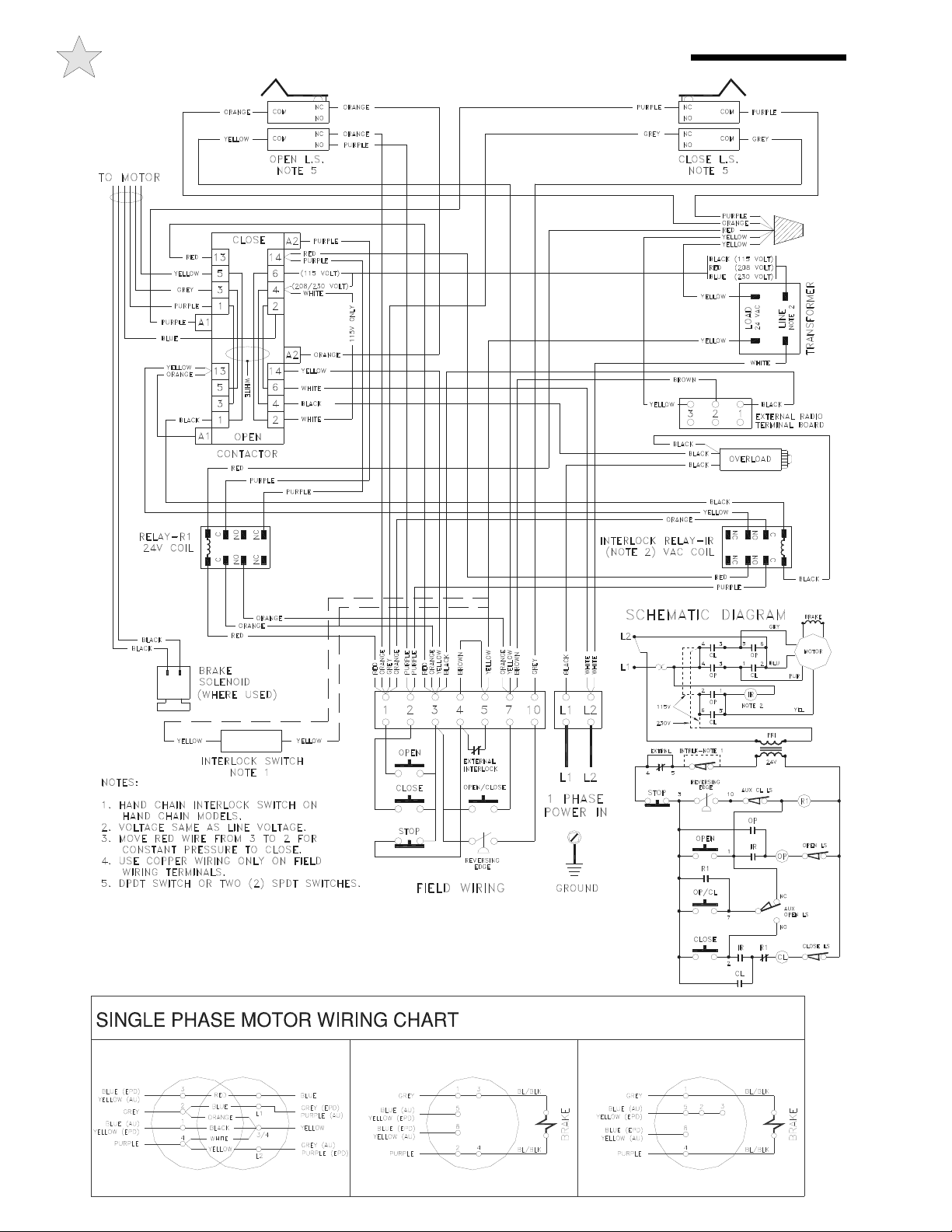
WIRING DIAGRAM/SCHEMATIC - SINGLE PHASE 18
SERVICE OR ADJUSTMENTS.
POWER BEFORE ATTEMPTING
CAUTION: DISCONNECT
EDGE & TEST MONTHLY.
CONNECT REVERSING
106847
107304
(EPD) - ALLSTAR SERIES T, J, AND H
(AU) - ALLSTAR SERIES AUD, AUJ, AND AUH
INCOMING LEADS TO TERMINALS 5 AND 8.
TO REVERSE MOTOR DIRECTION, SWITCH
DUAL VOLTAGE MOTOR - 115V 1P115V 1P
A.O. SMITH BALDOR
DUAL VOLTAGE MOTOR - 230V 1P
TO REVERSE MOTOR DIRECTION, SWITCH
INCOMING LEADS TO TERMINALS 5 AND 8.
BALDOR
TO REVERSE MOTOR, SWITCH LEADS 1 & 3 (115V); L1 & L2 (230V).
IF USED, CONNECT BRAKE WIRES TO 2 & 4 (115V); L1 & L2 (230V).
(312 SERIES)
230V 1P

WIRING DIAGRAM/SCHEMATIC - THREE PHASE
19
S
ERVI
C
E
O
R AD
JUS
TMENT
S
.
POWER BEFORE ATTEMPTING
CAUTION: DISCONNECT
AND TEST MONTHLY.
CONNECT REVERSING EDGE
106848
107304
230 VOLTS, 3 PHASE
TO REVERSE MOTOR DIRECTION, SWITCH
DUAL VOLTAGE MOTOR
3 PHASE MOTOR WIRING CHART
ANY TWO INCOMING LEADS.
SINGLE VOLTAGE MOTOR
575 VOLTS, 3 PHASE
TO REVERSE MOTOR DIRECTION, SWITCH
(EPD) - ALLSTAR SERIES T, J, AND H
TO REVERSE MOTOR DIRECTION, SWITCH
DUAL VOLTAGE MOTOR
460 VOLTS, 3 PHASE
ANY TWO INCOMING LEADS.
(AU) - ALLSTAR SERIES AUD, AUJ, AND AUH
ANY TWO INCOMING LEADS.

Manufacturer’s Limited Warranty
Linear LLC warrants its Allstar brand commercial door operators to be free from defect in material and workmanship for a period of two (2)
years from the date of purchase. To obtain service contact your dealer.
To obtain service under this warranty the buyer must obtain authorization instructions for the return of any goods from Linear before
returning the goods. The goods must be returned with complete identification, with copy of proof-of-purchase, freight prepaid and in
accordance with Linear’s instructions or they will not be accepted. In no event will Linear be responsible for goods returned without proper
authorization or identification.
Goods returned to Linear for warranty repair within the warranty period, which upon receipt by Linear are confirmed to be defective and
covered by this limited warranty, will be repaired or replaced at Linear’s sole option, at no cost and returned pre-paid. Defective parts will
be repaired or replaced with new or factory rebuilt parts at Linear’s sole option.
This limited warranty does not cover non-defect damage, damage caused by unreasonable use, damage caused by improper installation or
care, vandalism or lightning, fire or excessive heat, flood or other acts of God (including, but not limited to misuse, abuse or alterations,
failure to provide reasonable and necessary maintenance), labor charges for dismantling or reinstalling a repaired or replaced unit, or
replacement batteries.
These warranties are in lieu of all other warranties, either expressed or implied. All implied warranties of merchantability and/or fitness for a
particular purpose are hereby disclaimed and excluded. Under no circumstances shall Linear be liable for consequential, incidental or special
damages arising in connection with the use or inability to use this product. In no event shall Linear’s liability for breach of warranty, breach
of contract, negligence or strict liability exceed the cost of the product covered hereby. No person is authorized to assume for Linear any
other liability in connection with the sale of this product.
This warranty gives you specific legal rights. You may also have other rights which vary from state to state. Warranty effective after
October 1st, 2007.
For Information:
877-441-9300 800-421-1587 www.allstarcorp.com
20
P/N 190-107813 Rev. D August 2007Copyright © 2007 Linear LLC
This Door Operator is built in the USA and
complies with all requirements of
ANSI/UL Standard 325.
Table of contents
Popular Door Opening System manuals by other brands

Teckentrup
Teckentrup dw 62-2ME Operating / Assembly Instructions & Installation Data

Record
Record S20 Series user manual

Genius
Genius Mistral Instructions for use

Mobotix
Mobotix DoorMaster MX-Door2-INT Quick install

CAMDEN
CAMDEN CX-ED1959 installation instructions

Assa Abloy
Assa Abloy Besam SL500 user manual


Eco
Eco SR TS-61 B Assembly instruction

Dormakaba
Dormakaba ED900 installation instructions

Assa Abloy
Assa Abloy Norton Narrow Profile Series installation instructions

Assa Abloy
Assa Abloy Norton 8000 Series installation instructions

GEZE
GEZE ECturn Inside Installation and service instructions

Falcon
Falcon SC81 installation instructions