CX-ED1959 Outdoor Gate Electric Strike
INSTALLATION INSTRUCTIONS
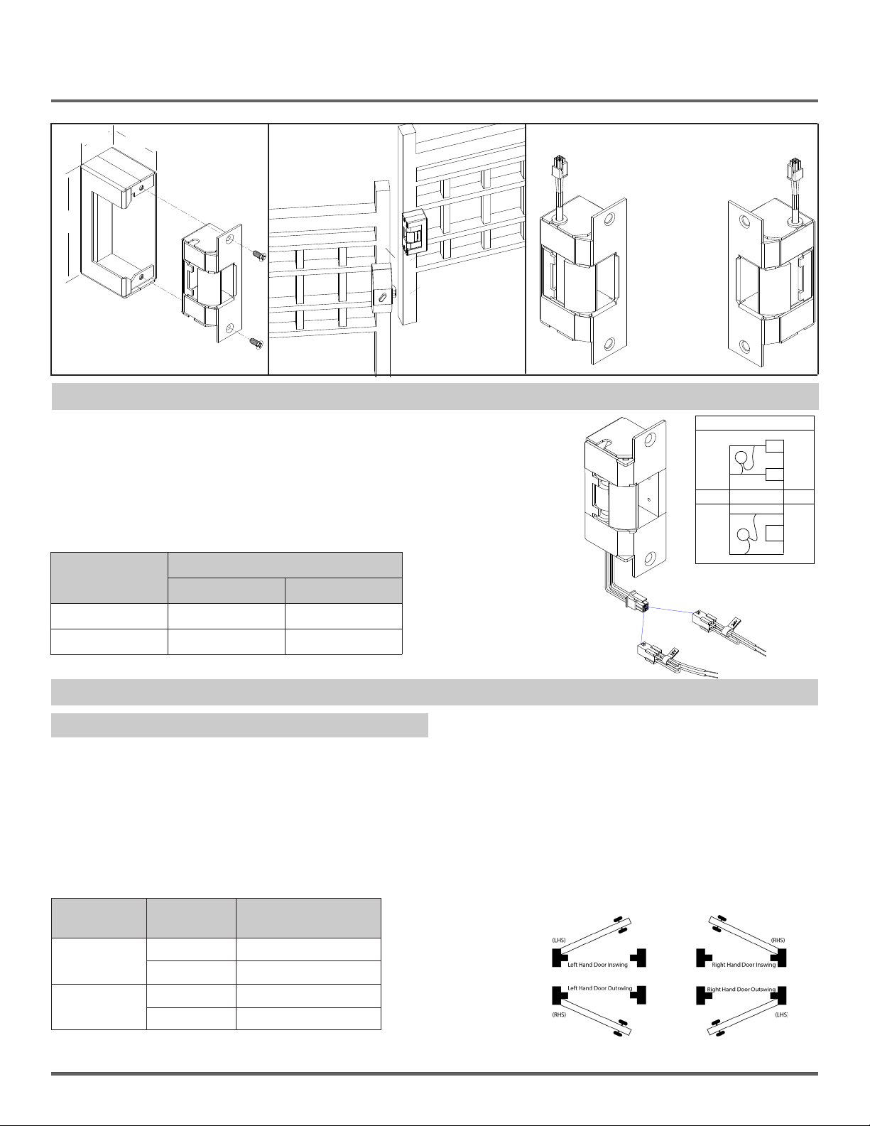
4. INSTALLATION
Note:
Choose the appropriate option based on the type of frame or
gate you have. For a wooden jamb, drill holes to install the strike and use
supplied #10 - 1 x 1/4” self-tapping screws for mounting.
Option 1 For Hollow Metal Frame
1. Determine the location where the electric strike will be installed on
the door frame. This should align with the location of the latch on the
door.
2. Mark the outline of the electric strike on the jamb using a pencil or
marker.
3. Using a chisel, router, or jamb saw, cut out the mortise in the jamb
along the marked outline. The size of the mortise should match the
size of the electric strike. Make sure to cut to the depth specied in
gure 4.1.
4. Drill holes to mount the provided mounting bracket using 1/4” drill
bits.
5. Use provided #12 - 24 x 1/2” machine screws to mount the brackets
included in the package.
6. Test t the electric strike in the mortise. Make any necessary adjust-
ments to ensure a proper t.
7. Mount the strike onto the bracket using the included #12 - 24 x
1/2” machine screws.
Option 2 For ANSI Frame
8. Make sure that the door jamb/gate has an appropriate cutout to
accommodate strike assembly, If not then, refer to the dimension
section and cut the jamb if required.
9. Use the supplied #12 - 24 x 1/2” machine screws to secure it.
Option 3 Gate Mounting
10. Secure the supplied mounting box onto the gate through welding
or with the help of screws (see gure 4.3).
11. Secure the strike inside the box with the help of supplied #12 - 24 x
1/2” machine screws (see gure 4.2).
12. Run the wires from the electric strike through the jamb and into the
door. Connect the wires to the appropriate terminals on the electric
strike as mentioned in section 5.
89mm
[3 1/2”]
43mm
[1 11/16”] 41mm
[1 5/8”]
155mm
[6 1/8”]
122mm
[4 13/16”]
89mm
[3 1/2”]
41mm
[1 5/8”]
32mm
[1 1/2”]
122mm
[4 13/16”]
105mm
[4 1/8”]
43mm
[1 11/16”]
HORIZONTAL
CENTERLINE
JAMB
DRILL & COUNTERSINK
FOR
12-24x1/2” FLAT-HEAD
SCREW(2PCS)
PRESSED METAL NUT
VERTICAL CENTERLINE
12-24 1/2” FLAT-HEAD
SCREW(4pcs)
HORIZONTAL
CENTERLINE
JAMB
DRILL & COUNTERSINK
FOR
12-24x1/2” FLAT-HEAD
SCREW(2PCS)
PRESSED METAL NUT
VERTICAL CENTERLINE
Red
Green
Black
Blue
12V
24V
Black
Red
Blue
Green
(+12V)
(-)
Varistor
(+24V)
(-)
Varistor
Option 1: Hollow Metal
Figure 4.1
Page 2 of 4
Option 2: ANSI