7
IMPORTANT SAFETY INSTRUCTIONS
WARNING: Opening of the SolShare must only be performed by a certied electrician.
WARNING: This equipment is connected to multiple sources of supply. Isolate all supplies before working on this equipment.
Each input circuit and each output circuit represent a source of supply.
WARNING: The specied shutdown procedure must be followed prior to working on this equipment.
WARNING: This equipment must be permanently earthed.
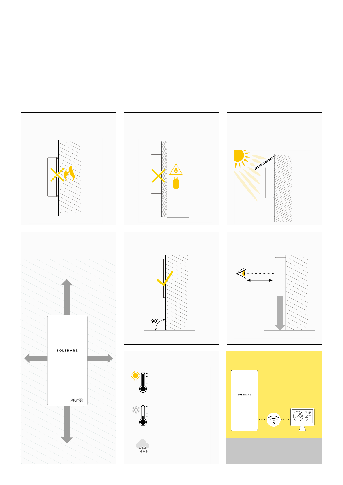
WARNING: This product relies on passive cooling, install in a well-ventilated location in accordance with the mounting instructions.
CAUTION: HEAVY OBJECT – This product has a weight of approximately 38kg. Un-boxing and mounting the product requires
2 people.
CAUTION: Residual Current Devices and Earth Leakage Breakers must not be used as Overcurrent Protection devices in Solshare
Output circuits.
CAUTION: The SolShare will impose a current dependent voltage drop/rise which should be taken into account during design of
the installation. Specications are given in the Technical Data sheet.
CAUTION: The unit must be operated according to the technical specication datasheet provided with the unit.
CAUTION: Installations may vary depending on the existing electrical infrastructure and local electrical safety standard. It is the
responsibility of the electrician to ensure their installation meets the local electrical safety standard.
NOTE: Use only copper conductors rated for a minimum of 90 degrees Celsius.
NOTE: The symbol appears at grounding points within the SolShare equipment. This symbol is also used in the manual.
Handling and Safety Instructions
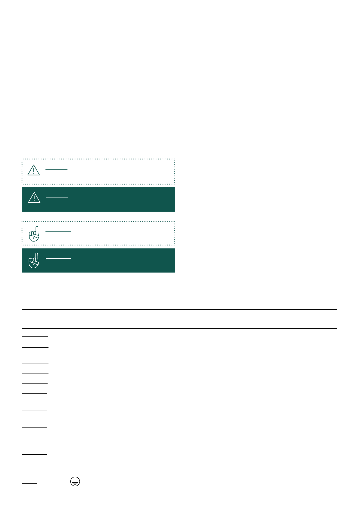
SAFETY SYMBOLS INFORMATION
The following safety symbols are used in this document. Familiarise yourself with the symbols and their meaning before
installing or operating the system:
Important:
xxxxx xxxx xxxx xxx xxxx xx xxxx xxx xxxx
Important:
xxxxx xxxx xxxx xxx xxxx xx xxxx xxx xxxx
Warning:
xxxxx xxxx xxxx xxx xxxx xx xxxx xxx xxxx
This symbol denotes a critical safety instruction that must
be followed to ensure safety of installer and safe operation
of the SolShare once commissioned. This box is sometimes
denoted in green to provide further emphasis.
This symbol indicates an instruction which will ensure
proper operation of the SolShare once commissioned or
will help with the installation efficiency. This same box is
sometimes denoted in green to provide further emphasis.
This guide is provided to help the installer understand
the standard SolShare installation procedure.
Installations may vary depending on the existing electrical
infrastructure and local electrical safety standard. It is the
responsibility of the electrician to ensure their installation
meets the local electrical safety standard.
During installation, testing and inspection, adherence to all
the handling and safety instructions is mandatory. Failure
to do so may result in injury or loss of life and damage
to the equipment.
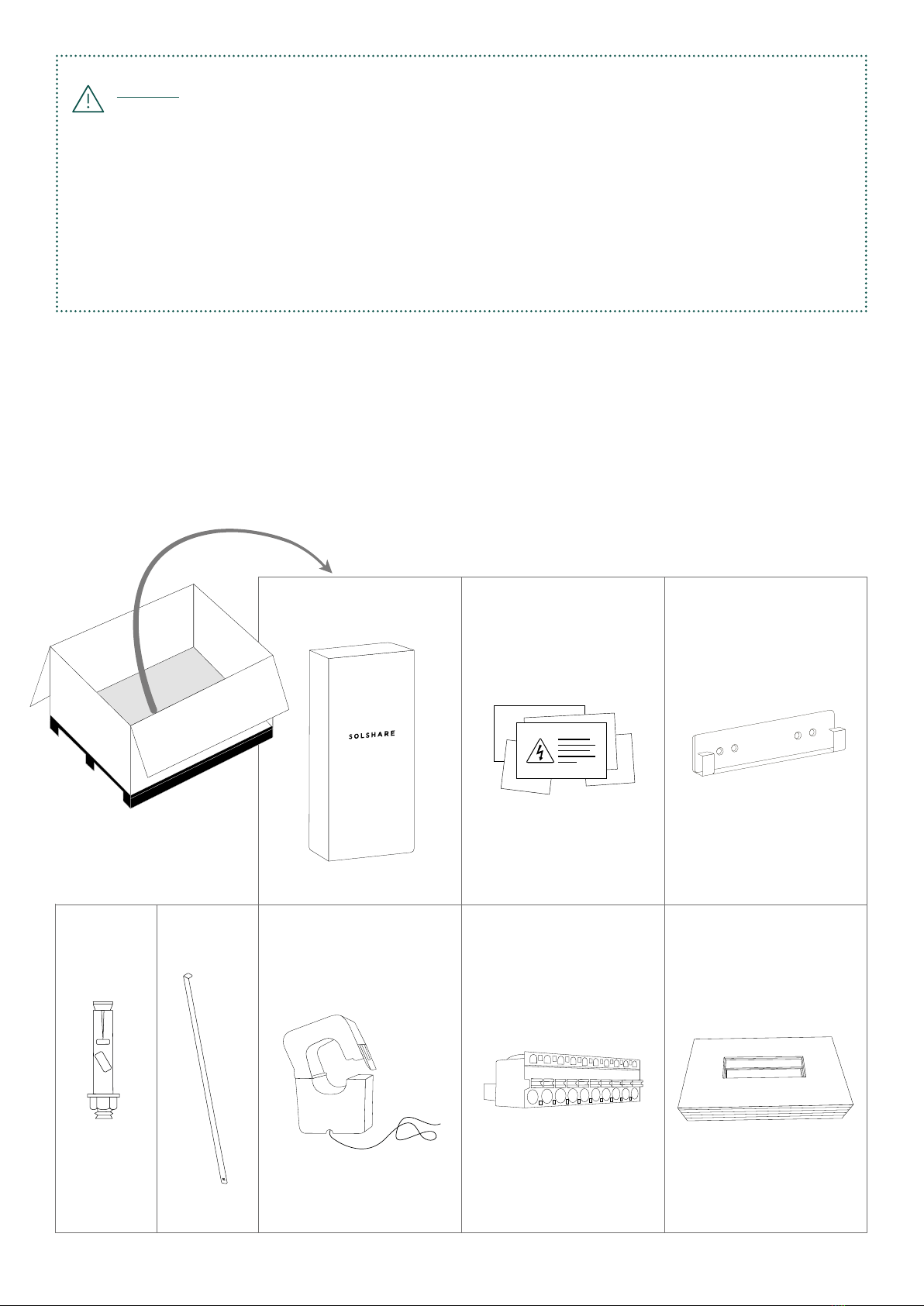
Warning:
xxxxx xxxx xxxx xxx xxxx xx xxxx xxx xxxx
SAVE THESE INSTRUCTIONS. This manual contains important instructions for the SolShare 3P-35A that shall be
followed during installation and maintenance of the power division control system.