Allume SolShare User manual

1
SolShare
Installation Manual

2
Australia - Version 2.1
This manual is intended for installations in Australia.
It is subject to change. Please check our website at
www.allumeenergy.com.au for the most up-to-date manual version.
AE-PN-081
© Copyright – Allume Energy - All rights reserved.
This manual accompanies our equipment for use by the end users.
The technical instructions and illustrations contained in this manual are to be treated as condential and no part may be reproduced without the prior
written permission of Allume Energy and end users may not divulge the information contained herein or use this manual for purposes other than those
strictly connected with correct use of the equipment.
All information and specications are subject to change without notice.

3
Summary
Commissioning Document
I/ What’s in the box
II/ Mounting the SolShare
A. Installation site selection
B. Installation
III/ Electrical connection
A. Input / Output connections
B. Output connection to main switchboard
C. Running current transformer tails
D. Current transformers to SolShare connections
E. Current transformer clipping
F. Launch the SolShare
p05
p06
p08
p08
p09
p10
p10
p12
p13
p13
p14
p14

4
Hello
Thank you for purchasing a SolShare system.
You are supporting the growth of cutting edge Australian
made solar technology. Due to the novelty of this product,
this installation will likely be dierent from any other piece
of solar technology you have installed in the past. As a
result, please follow the guidelines in this manual carefully.
Your system is designed to meet all Australian conditions,
regulations and codes. This guide provides the general
instruction of the installation procedure of the SolShare.
If you have questions or feedback on the product or this
manual, feel free to reach out to Allume on +61 394 270 005
and ask for a technical representative. Otherwise, you can
email support@allumeenergy.com.au with any queries.

5
Commissioning Document
To be completed during installation
Serial Number:
Installer name: Company:
SolShare Connection
Unit Connected (eg: Apt 1, Unit B, Common light & power, No connection)
Single-Phase Three-Phase
R1
W1
B1
R2
W2
B2
R3
W3
B3
R4
W4
B4
R5
W5
B5
Unit Connection Identier
OR
OR
OR
OR
OR
Installation Address:
State: Postcode: Country:

6
Check for Transport Damage
Make sure the SolShare is intact following transportation. If there are any signs of visible damage, please contact
your dealer immediately. Carefully check that all of the components have been supplied. If anything is missing,
contact your dealer.
I/ What’s in the box
Mounting bracket Fastener
SOLSHARE
Split current transformer
with 10m tails
CT connector block
Ethernet cable (required if
more than one SolShare
is being daisy chained)
SolShare unit Cable labels and
switchboard labels
x 15x 4
x 1
x 2 x 3
Warning:
- Make sure to read over, fully understand and strictly follow the detailed instructions of the user
manual and other related regulations before installing the equipment.
- Any violation could result in personal death or injury, or damage to the device.
- Installation is only to be conducted by a certied electrician.
- This guide is provided to help the installer understand the standard SolShare installation procedure.
Installations may vary depending on the existing electrical infrastructure and local electrical safety
standard. It is the responsibility of the electrician to ensure their installation meets the local
electrical safety standard.
- This product has a weight of approximately 38kg. Its un-boxing and mounting requires 2 people.
x 1

7
Installation overview
Electricity Meter Panel
Unit main switches
XXXXXX
M1
XXXXXX
M2
XXXXXX
M3
XXXXXX
M4
654321 7 8 9 10 11 12 13 14 15
XXXXXX
M5
XXXXXX
M6
XXXXXX
M7
XXXXXX
M8
XXXXXX
M9
XXXXXX
M10
XXXXXX
M11
XXXXXX
M12
XXXXXX
M13
XXXXXX
M14
XXXXXX
M15
SOLSHARE
from
inverter
main switch
solar isolator
minimum
150mm
A single SolShare unit can distribute the power generated
from a single solar system to up to 15 single-phase
or 5 three-phase units (or a combination of the two).
The SolShare takes a single three-phase input from a
grid-connected solar inverter(s) and connects to each
participating unit on the load side of their unit main
switch (a.k.a. unit isolator) at the unit main switchboard.
A solar isolator is required on each output (ideally
located within the unit main switchboard) between the
SolShare and each unit’s main switch. This allows for
the isolation of the SolShare and the solar supply of
any of the connected units.
A typical installation conguration is displayed below.
Explained
on p13
Explained
on p12

8
II/ Mounting the SolShare
A. Installation site selection
Do not mount the SolShare
on ammable wall material
Do not mount the SolShare near
ammable material or gases
Requirement for
installation space
90˚
Mounted Vertically
90˚
Mounted Vertically
Environmental boundaries
90˚
Mounted Vertically
Max ambient
temperature:
45°C (+140°F)
Min ambient
temperature:
-10°C (-13°F)
Relative humidity:
0-100%
90˚
Mounted Vertically
90˚
Mounted Vertically
Mount vertically Install in an easy to observe
and operate location
90˚
Mounted Vertically
Do not mount the SolShare
in direct sunlight
≈1200 mm
400 mm
300 mm
150 mm150 mm
To minimise cabling required, the SolShare should be
mounted as close to the main switchboard (tenancy
isolator board) as possible.
To allow for easy installation and maintenance ensure
that there is adequate space surrounding the SolShare
and that it is mounted at a convenient height. Please
ensure the following mounting requirements are also
met when selecting the location of the SolShare.

9
B. Installation
1
3
2
Important:
- The mounting wall and fastener selection is at the discretion of the installer. Allume Energy take no
responsibility in the appropriate site selection of the SolShare or the appropriate bracket fastener choice.
- Weight rating fasteners should be rated to at least 30kg of shear force per fastener.
4
785 +/- 5 mm
Follow the steps below to mount the SolShare:
1. Firmly secure the mounting brackets to the chosen
wall for installation. Allume Energy recommend using
the provided fasteners to attach the brackets into a
suitable stone or masonry wall. If another wall material
has been chosen for installation, please use suitable
fasteners with at least 30kg shear force per fastener.
2. Lift the SolShare onto the mounting brackets
as directed in the diagram. Check both top
and bottom brackets are secure.
3. Insert the locking bolt through the SolShare
top mounting bracket and secure at both ends.
4. Ensure the SolShare is securely fastened to
the wall and locked into place.

10
III/ Electrical connection
1 2
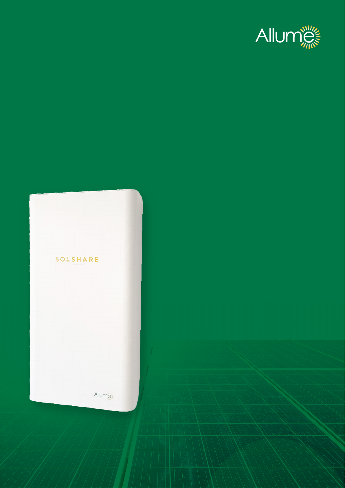
To reveal the lower section, slide cover up about
15cm. Whilst sliding cover upwards, pull cover gently
towards you. This will ensure it nds the locking slot.
Box as you nd it, closed. Unscrew the 4 screws
on the underside of the SolShare to allow access to
connection terminals. Retain screws to replace later.
Important:
The cover should lock into place when it’s pulled up properly. Before beginning wiring ensure cover
is locked in place by pulling down rmly. To bring cover back to initial position, lift cover upwards
and away from you, then allow to slide down back into place.
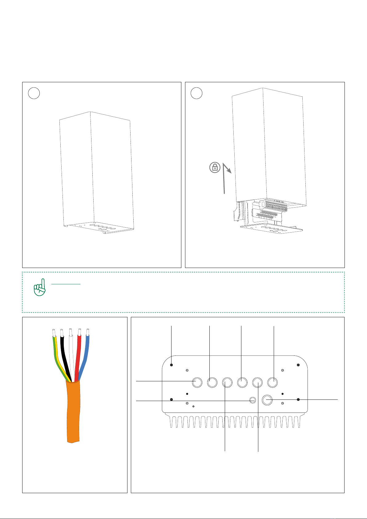
A. Input / Output Connections
1. Lift up cover to reveal the lower section of the box, where the electrical connections are made.
CAT-5
cable
gland
input
solar
output
R1, W1, B1
output
R2, W2, B2
output
R3, W3, B3
output
R4, W4, B4
CT
conduit
gland
output
R5, W5, B5
The AC cables
Please choose appropriately
gauged cables as per solar system
size. The use of four core and earth
(4c+e) is recommended.
SolShare underside view
Each output membrane gland will correspond to the output
of 3 single-phase units or 1 three-phase unit. The leftmost
membrane gland corresponds to the solar input.
Cover
retainer
screws

11
All wiring is conducted on the AC side of the inverter.
The SolShare requires a three-phase, grid-connected
inverter to be used in the PV installation. The solar
input cable must come from a single inverter main
switch, ideally located in an accessible location from
the main switchboard.
To wire the input cable and output cables into
the SolShare the following steps should be taken:
1. Measure out the 4c+e cable and cut to appropriate length.
2. Strip cable sheath back by approximately 100mm.
3. Push cable through membrane gland ensuring
outer sheath extends to within enclosure.
4. Cut and connect earth and neutral cables to their
respective bus bars.
5. Cut and connect phase cables as per the diagram above.
Area of input / output:
The 4c+e cables should be inserted
through the appropriate glands, as per the
‘SolShare underside view’ diagram on the
previous page.
Connectors
Earth Bar
Neutral Bar
Input solar Output 1 Output 2
Connectors
Input solar Output 1
Earth Bar
Neutral Bar
R1 W1 B1 R2 W2 B2 R3 W3 B3 R4 W4
B4
R W B
Important:
Label the tail of the cable to ensure the correct cable is wired into the correct unit in the main switchboard.
Warning:
Ensure the input earth and neutral and at least one output earth and neutral are connected
to their respective busbars.

12
B. Output Connection
to Main Switchboard
FROM GRID
R1 B1 R2R1 B1 R2
W1 W1
TO UNIT TO UNIT TO UNIT
ADDITIONAL ISOLATOR
MAIN SWITCH
FROM
SOLAR
FROM
SOLAR
FROM
SOLAR
FROM
SOLAR
ADDITIONAL
SOLAR
ISOLATOR
A solar isolator must be installed between the SolShare
output and unit main switch for each participating unit.
For single-phase meters this should be a single
pole main circuit breaker (MCB), for three-phase
customers this should be a three pole MCB.
Ideally these solar isolators should be mounted within
the existing main switchboard. If there is not adequate
space to do this, Allume recommends they be installed
in a location that is easily accessible from the main
switchboard. If positioned seperately, ensure clear
labeling in the main switchboard of the location of
solar isolators.
The outputs from the solar must be wired to the solar
isolators. The outputs of the solar isolators must be
wired on the load side of the unit’s main switch.
Ensure each output is labelled as per the gure below.
This will help later on in the installation when wiring
the current transformers to each unit.
Important:
Make sure to label both ends of each solar cable.
LOAD
SIDE
SERVICE
SIDE
Electricity Meter panel
XXXXXX
M1
XXXXXX
M2
XXXXXX
M3
XXXXXX
M4
654321 7 8 9 10 11 12 13 14 15
XXXXXX
M5
XXXXXX
M6
XXXXXX
M7
XXXXXX
M8
XXXXXX
M9
XXXXXX
M10
XXXXXX
M11
XXXXXX
M12
XXXXXX
M13
XXXXXX
M14
XXXXXX
M15
Area of focus:
Main switchboard
Important:
Ensure the phase of the solar supply correctly matches the phase of the unit’s supply from the grid.

13
C. Running current
transformer tails
R1
R1
1. Run conduit from Solshare to main switchboard.
(conduit gland is rightmost membrane gland on
underside of SolShare)
2. Label tails and head of current transformers (CTs)
as per the solar cable labels in the previous step
(see gure on the right).
3. Run tails of CTs from main switchboard to
SolShare through conduit.
Important:
Ensure labeling of head and tails of CT cables before feeding through conduit.
Electricity Meter panel
Unit main switches
XXXXXX
M1
XXXXXX
M2
XXXXXX
M3
XXXXXX
M4
654321 7 8 9 10 11 12 13 14 15
XXXXXX
M5
XXXXXX
M6
XXXXXX
M7
XXXXXX
M8
XXXXXX
M9
XXXXXX
M10
XXXXXX
M11
XXXXXX
M12
XXXXXX
M13
XXXXXX
M14
XXXXXX
M15
Area of focus:
Conduit cable
D. Current transformers to SolShare connections
Wiring tails to Solshare:
1. Connect the CT cabling to the CT connector
block, as per the diagram to the right. To do this:
- Push the orange tab in and hold.
- Feed the CT cable into the hole.
- Once inserted, release the orange tab.
- Conrm cable is secure by giving it a gentle tug.
2. Repeat for all CT cables of the red phase.
3. Repeat steps 1 & 2 for white and blue phase
connector blocks.
4. Plug each CT connector block into the
corresponding socket of the SolShare.
R1
R2
R3
R4
R5
Important:
Make sure colours and order of CT connections are exactly the same as the image.

14
E. Current transformer clipping
Clipping the current transformers onto the service
side cable:
1. Match the labelled CTs with their corresponding
labelled service supply cable.
2. Conrm correct polarity of the CT by ensuring
the arrow on the CT head matches the current
ow direction on service supply cable.
3. Clip CT over service supply cable.
SOLSHARE 50
Polarity
of current
transformers
down towards
load
R1 R1
FROM
SOLAR
SERVICE
SIDE
LOAD
SIDE
F. Launching the SolShare
SOLSHARE
Important:
Before commissioning re-check all CTs and output cables are connected as per their labels.
Important:
Make sure that each CT is clipped
to the corresponding unit.
To commission the SolShare:
1. Pull down cover of SolShare. Fasten shut by replacing
the 4 screws on the underside of the SolShare, that
were removed in section III/A.1.
2. Switch on all solar isolators and unit main switches.
3. Switch on inverter main switch.
4. Monitor inverter’s grid connect process until solar
begins outputting. If inverter cannot establish grid
connection call +61 394 270 005 or contact
support@allumeenergy.com.au.
5. Once solar begins outputting, please send an email
to support@allumeenergy.com.au to notify Allume
of SolShare commissioning. The email must include
a photo of the completed ‘Product Registration
document’ (see page 5)

This manual is intended for installations in Australia.
Specications are subject to changes without advanced notication.
Allume Energy Ltd.
www.allumeenergy.com.au
info@allumeenergy.com
+61 394 270 005
Other manuals for SolShare
3
Table of contents
Other Allume Inverter manuals
Popular Inverter manuals by other brands

Miller Electric
Miller Electric Blue Star 6000 owner's manual

KEHUA TECH
KEHUA TECH SPI-B2S Series user manual

FujiFilm
FujiFilm FRENIC-Mini instruction manual

Nidec
Nidec Leroy-Somer POWERDRIVE MD2CS installation guide

Generac Power Systems
Generac Power Systems RV 45 SERIES owner's manual

Craftsman
Craftsman 580.326300 owner's manual

Hoymiles
Hoymiles MI-600T user manual

Lust
Lust CDA3000-PLC System manual

Solectria Renewables
Solectria Renewables PVI 13KW Installation and operation manual

Mitsubishi Electric
Mitsubishi Electric 800 Series instruction manual

PEDROLLO
PEDROLLO TISSEL-200 Original instructions for use

Fuji Electric
Fuji Electric FVR-E11S-7EN instruction manual