Allume SolShare 100 User manual

1
SolShare
Installation Manual

2
AE-PN-083-V2.2
© Copyright – Allume Energy - All rights reserved.
This manual accompanies our equipment for use by the end users.
The technical instructions and illustrations contained in this manual are to be treated as condential and no part may be reproduced without the prior
written permission of Allume Energy and end users may not divulge the information contained herein or use this manual for purposes other than those
strictly connected with correct use of the equipment.
All information and specications are subject to change without notice.
USA - AE-PN-083-V2.2
This manual is intended for installations in the United States
of America. It is subject to change. Please check our website at
www.allumeenergy.com.au for the most up-to-date manual version.

3
Summary
Commissioning Document
Handling and Safety Instructions
I/ What’s in the box
II/ Mounting the SolShare
A. Installation site selection
B. Installation
III/ Electrical connection
A. Input / Output connections
B. Output connection to main switchboard
C. Running current transformer tails
D. Current transformers to SolShare connections
E. Current transformer clipping
F. Launch the SolShare
Appendix
Technical Specications
p05
p06
p07
p09
p09
p10
p11
p11
p15
p16
p16
p17
p17
p18
p21

4
Hello
Thank you for purchasing a SolShare system.
You are supporting the growth of cutting edge Australian
made solar technology. Due to the novelty of this product,
this installation will likely be dierent from any other piece
of solar technology you have installed in the past. As a
result, please follow the guidelines in this manual carefully.
Your system is designed to meet all United States conditions,
regulations and codes. This guide provides the general
instruction of the installation procedure of the SolShare.
If you have questions or feedback on the product or this
manual, feel free to reach out to Allume on +61 394 270 005
and ask for a technical representative. Otherwise, you can
email support@allumeenergy.com.au with any queries.

5
Commissioning Document
To be completed during installation
Serial Number:
Installer name: Company:
SolShare Connection
Unit Connected
(eg: Apt 1, Unit B, Common light & power, No connection)
Unit number
1-L1
2-L2
3-L1
4-L2
5-L1
6-L2
7-L1
8-L2
9-L1
10-L2
Unit Connection Identier
Installation Address:
State: Postcode: Country:

6
Important Safety Instructions
Warning: The SolShare cover must be opened only after the input and all output circuits are individually disconnected.
Warning: Ensure the SolShare is grounded prior to operation. This product must be connected to a grounded, metal, permanent
wiring system or an equipment-grounding conductor must be run with the circuit conductors and connected to the equipment
grounding terminal or lead on the product.
Warning: Opening of the SolShare must only be performed by certied electrician
Caution: The unit must be operated according to the technical specication datasheet provided with the unit
Caution: HEAVY OBJECT – This product has a weight of approximately 38kg. It’s un-boxing and mounting requires 2 people.
Note: The SolShare is Type 4 rated per the UL50E standard. Where used, cable glands should be rated to minimum NEMA 4
(or IP XX), otherwise the supplied blanking seal to remain.
Note: Use only copper conductors rated for a minimum of 90 degrees Celsius, 194 Fahrenheit.
Note: The symbol appears at grounding points within the SolShare equipment. This symbol is also used in the manual.
Handling and Safety Instructions
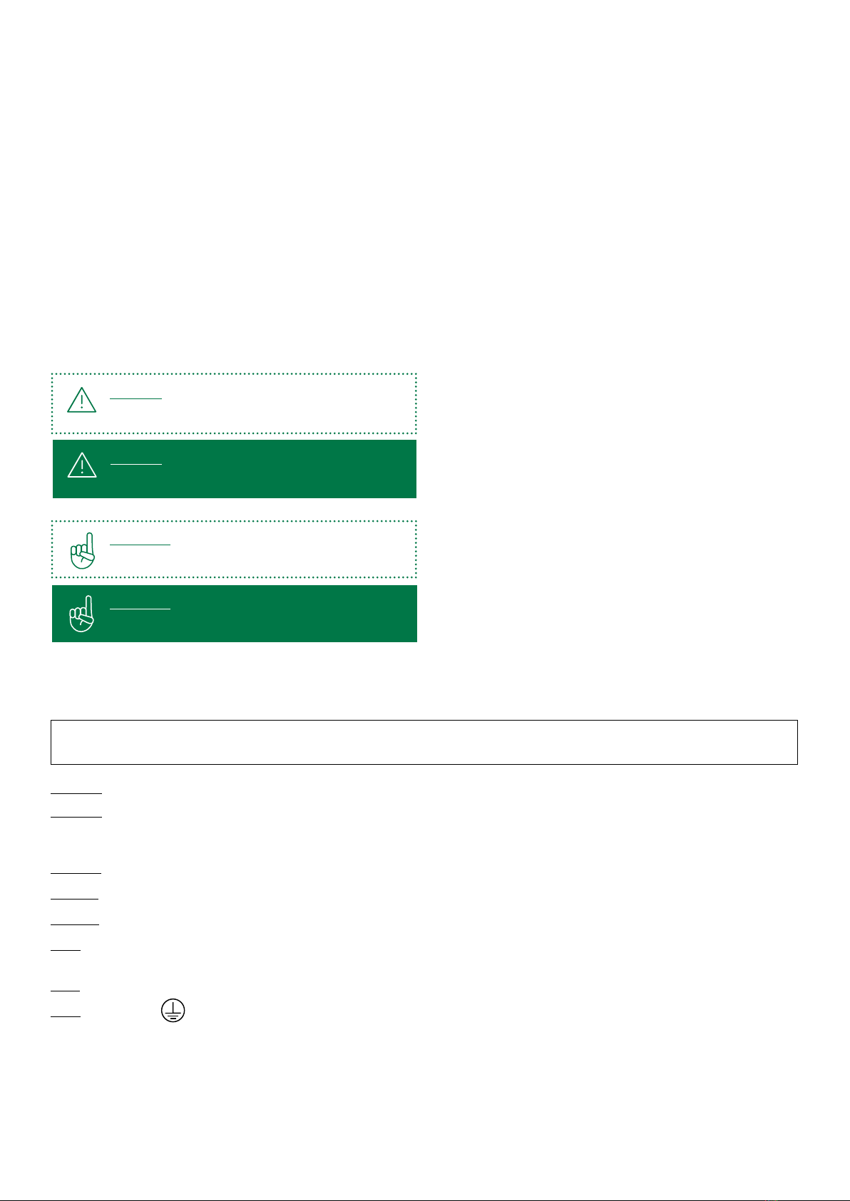
Safety Symbols Information
The following safety symbols are used in this document. Familiarise yourself with the symbols and their meaning before
installing or operating the system:
Important:
xxxxx xxxx xxxx xxx xxxx xx xxxx xxx xxxx
Important:
xxxxx xxxx xxxx xxx xxxx xx xxxx xxx xxxx
Warning:
xxxxx xxxx xxxx xxx xxxx xx xxxx xxx xxxx
This symbol denotes a critical safety instruction that must
be followed to ensure safety of installer and safe operation
of the SolShare once commissioned. This box is sometimes
denoted in green to provide further emphasis.
This symbol indicates an instruction which: will ensure
proper operation of the SolShare once commissioned or
will help with the installation efficiency. This same box is
sometimes denoted in green to provide further emphasis.
This guide is provided to help the installer understand
the standard SolShare installation procedure.
Installations may vary depending on the existing electrical
infrastructure and local electrical safety standard. It is the
responsibility of the electrician to ensure their installation
meets the local electrical safety standard.
During installation, testing and inspection, adherence to all
the handling and safety instructions is mandatory. Failure
to do so may result in injury or loss of life and damage
to the equipment.
Warning:
xxxxx xxxx xxxx xxx xxxx xx xxxx xxx xxxx
SAVE THESE INSTRUCTIONS. This manual contains important instructions for the SolShare 2P-100A that shall be
followed during installation and maintenance of the power division control system.

7
Check for Transport Damage
Make sure the SolShare is intact following transportation. If there are any signs of visible damage, please contact your dealer
immediately. Carefully check that all of the components have been supplied. If anything is missing, contact your dealer.
I/ What’s in the box
Mounting bracket Fastener Split current transformer
with 10m tails
CT connector block
SolShare unit Switchboard labels
x 15x 4
x 1
x 2 x 3
x 1
SOLSHARE
Antenna

8
Electricity Meter Panel - US version 2
SOLSHARE
XXXXXX
M1
XXXXXX
M2
XXXXXX
M3
XXXXXX
M4
XXXXXX
M5
XXXXXX
M6
XXXXXX
M7
XXXXXX
M10
XXXXXX
M8
XXXXXX
M9
Installation overview
main switches
Electricity Meter Panel
solar circuit breakers
A single SolShare unit can distribute the power generated
from a single solar system to up to 10 multifamily units.
The SolShare takes a single split-phase input from a grid-
connected solar inverter(s) and connects to each participating
unit on a single line (L1 or L2) to the load side of their Unit
Main Switch (a.k.a. unit circuit breaker) at their meter panel.
A single-pole Unit Solar Circuit Breaker is required on each
output between the SolShare and each unit’s main switch.
This allows for the isolation of the SolShare and the solar
supply of any of the connected units.
A typical installation conguration is displayed below.
minimum
150mm
Explained
on p16
Explained
on p15
split phase
from inverter

9
II/ Mounting the SolShare
A. Installation site selection
Do not mount the SolShare
on ammable wall material
Do not mount the SolShare near
ammable material or gases
Requirement for
installation space
90˚
Mounted Vertically
90˚
Mounted Vertically
Environmental boundaries
90˚
Mounted Vertically
Max ambient
temperature:
50°C (+122°F)
Min ambient
temperature:
-10°C (-13°F)
Relative humidity:
0-90%
90˚
Mounted Vertically
Mount vertically Install in an easy to observe
and operate location
90˚
Mounted Vertically
90˚
Mounted Vertically
≈1200 mm
To minimise cabling required, the SolShare should be
mounted as close to the main switchboard (tenancy isolator
board) as possible.
To allow for easy installation and maintenance ensure that
there is adequate space surrounding the SolShare and
that it is mounted at a convenient height. Please ensure
the following mounting requirements are also met when
selecting the location of the SolShare.
Do not mount in direct sunlight
150 mm150 mm
500 mm500 mm
Pre-installment requirement
To do before mounting the bracket.
Screw in and lift up the antenna
vertically as shown here.

10
B. Installation
1
3
2
4
780 mm
Important:
- The mounting wall and fastener selection is at the discretion of the installer. Allume Energy take no responsibility
in the appropriate site selection of the SolShare or the appropriate bracket fastener choice.
- Weight rating fasteners should be rated to at least 30kg of shear force per fastener.
Before mounting the SolShare, please screw in the antenna
(see pre-installation diagram on page 8). Then follow the steps
below to mount the brackets and enclosure:
1. Firmly secure the mounting brackets to the chosen wall for
installation. Allume Energy recommend using the provided
fasteners to attach the brackets into a suitable stone or
masonry wall. If another wall material has been chosen for
installation, please use suitable fasteners with at least
30kg shear force per fastener.
2. Lift the SolShare onto the mounting brackets as directed in
the diagram. Check both top and bottom brackets are secure.
3. Insert the locking bolt through the SolShare top mounting
bracket and secure at both ends.
4. Ensure the SolShare is securely fastened to the wall
and locked into place.

11
III/ Electrical connection
1 2
To reveal the lower section, slide cover up about 15cm.
Whilst sliding cover upwards, pull cover gently towards you.
This will ensure it nds the locking slot.
Box as you nd it, closed. Unscrew the 4 screws on the
underside of the SolShare to allow access to connection
terminals. Retain screws to replace later.
Important:
The cover should lock into place when it’s pulled up properly. Before beginning wiring ensure cover is locked in
place by pulling down rmly. To bring cover back to initial position, lift cover upwards and away from you, then
allow to slide down back into place.
A. Input / Output Connections
1. Lift up cover to reveal the lower section of the box, where the electrical connections are made.
INPUT
SOLAR
OUTPUT
1, 2
OUTPUT
3 , 4
OUTPUT
5 , 6
OUTPUT
7 , 8
DEMAND
CT INPUT
REDUNDANT
HOLE, LEAVE
PLUG IN
PLACE
OUTPUT
9 , 10
COVER
RETAINER
SCREWS
The AC cables
Please choose appropriately gauged
cables as per solar system size. The
use of four core and earth (4c+e) is
recommended. All input and output
cables should be rated to total
generation capacity of inverter.
SolShare underside view
Each output gland will correspond to the output of an L1 and L2 cable,
corresponding to the solar supply for two units. The leftmost membrane
gland corresponds to the solar input.

12
Gland & Conduit Installation
1. Select appropriate glands to replace the plugs on the underside of the SolShare. (See Appendix for details)
2. Replace plugs with input gland and required number of output glands.
- The number of output glands required will depend on the number of units connected to the SolShare.
- One gland for every 2 units is recommended. However, fewer glands may be used if cable gauge permits.
3. Run input conduit from inverter to SolShare input (via Solar Main Switch)
4. Run output conduits from out glands to Unit Solar Circuit Breakers
TO METER
PANEL
FROM
INVERTER
PRE-EXISTING
EARTH CONNECTIONS
TO ENCLOSURE
Important:
The Unit Solar Circuit Breakers can be mounted on the meter panel or in a separate enclosure adjacent
to meter panel (as pictured on page 8)
Important:
- No wiring loops of excess conductor length are allowed to be made. Field wiring of all circuits must maintain
1/4” separation from all other circuits
- All electrical connections including sensor circuits, made between the Allume Energy SolShare 100 and
an electrical distribution panel shall be run through conduit or another type of NEC compliant raceway

13
IN (N) OUT (N) IN (L1) IN (L2) 1(L1) 2(L2) 3(L1) 4(L2) 5(L1) 6(L2) 7(L1) 8(L2) 9(L1) 10(L2)
SOLAR INPUT OUTPUT 1-2 OUTPUT 3-4 5-6 7-8 9-10
NEUTRALS INPUTS OUTPUTS
ONLY CONNECT THE
EARTH CABLES OF
THE INPUT AND FIRST
OUTPUT
AC OUTPUT (NEUTRAL)
IS NOT BONDED TO
GROUND.
Terminal block - Neutral & Phase connections
Conductors from 12 AWG (4mm2) to 4 AWG (25mm2)
Stripping length 14mm
Tightening torque 18 lb-in (2Nm)
Earth Connection
Please refer to Appendix (p19) for Conductor Specication options.
1. Run input earth from inverter and connect to the SolShare’s earth bar (as shown above)
2. Run output earth cable from earth point in meter panel and connect to the SolShare’s earth bar (as shown above).
Warning:
Only one earth output should be wired from SolShare to meter panel.
Tightening Torque - IN-LBS (N.m)
Conductor size Attachment method / Bare wire / Termial / Lug / Ferrule
14 AWG - 10 AWG 35 [4.0]
8 AWG 40 [4.5]
6 AWG - 4 AWG 50 [5.6]

14
Neutral Connection
Please refer to Appendix (p20) for Terminal Block Connection options.
1. Run input neutral from inverter and connect to the SolShare’s neutral input connector (as shown above)
2. Run output neutral cable from neutral point in meter panel and connect to the SolShare’s neutral output connector
(as shown above).
Input Power Connection
1. Run input L1 and L2 from inverter and connect to the SolShare’s L1 and L2 input connectors (as shown above)
Output Power Connection
1. Complete column 2 of the Commissioning Document on page 5, allocating each SolShare output to a unit/apmt number.
2. Cut output power cables to appropriate length to reach from SolShare output to Unit Solar Circuit Breakers. Label both
ends of these cables with the unit/apmt number.
3. Run cables between SolShare and Unit Solar Circuit Breakers. Terminate cables to appropriate SolShare output
connectors as per the conguration in step 1.
Warning:
Only one neutral output should be wired from SolShare to meter panel.
Important:
The Unit Solar Circuit Breakers can be mounted on the meter panel or in a separate enclosure adjacent
to meter panel (as pictured on page 8)
Warning:
No wiring loops of excess conductor length are allowed to be made. Field wiring of all circuits must
maintain 1/4” separation from all other circuits.
Warning:
Neutral bonding to protective ground must take place only at the main distribution panel.

15
SOLSHARE
XXXXXX
M1 M2
XXXXXX XXXXXX
M3
XXXXXX
M4
XXXXXX
M5 M6
XXXXXX XXXXXX
M7
XXXXXX
M10
XXXXXX
M8 M9
XXXXXX
B. Output Connection
to Main Switchboard
A solar circuit breaker must be installed between the SolShare
output and unit main switch for each participating unit.
For single-phase meters this should be a single pole main
circuit breaker (MCB), for three-phase customers this should
be a three pole MCB.
Ideally these solar circuit breakers should be mounted within
the existing main switchboard. If there is not adequate
space to do this, Allume recommends they be installed in a
location that is easily accessible from the main switchboard.
If positioned seperately, ensure clear labeling in the main
switchboard of the location of solar circuit breakers.
The outputs from the solar must be wired to the solar circuit
breakers. The outputs of the solar circuit breakers must be
wired on the load side of the unit’s main switch.
Ensure each output is labelled as per the gure below. This
will help later on in the installation when wiring the current
transformers to each unit.
Important:
Make sure to label both ends of each solar cable.
Area of focus:
Main switchboard
Important:
Connect only one line of solar to each unit. Make sure the solar supplier line alternates between each unit
as shown below.
FROM SOLAR FROM GRID
SERVICE SIDE
1(L1) 1(L1)
2(L2) 1(L2)
3(L3) 2(L1) 3(L1) 4(L1)4(L4) 2(L2) 3(L2) 4(L2)
TO UNIT
LOAD SIDE
TO UNIT
LOAD SIDE
Warning:
OCPD (Over Current Protective Devices) provided between the AC line and an inverter operating in parallel
with the grid are required to be rated for bi-directional use.

16
C. Running current transformer tails
SOLSHARE
XXXXXX
M1 M2
XXXXXX XXXXXX
M3
XXXXXX
M4
XXXXXX
M5 M6
XXXXXX XXXXXX
M7
XXXXXX
M10
XXXXXX
M8
XXXXXX
M9
Area of focus:
Conduit cable
D. Current transformers to SolShare connections
Wiring tails to Solshare:
1. Connect the CT cabling to the CT connector
block, as per the diagram to the right. To do this:
- Push the orange tab in and hold.
- Feed the CT cable into the hole.
- Once inserted, release the orange tab.
- Conrm cable is secure by giving it a gentle tug.
2. Repeat for all CT cables of the red phase.
3. Repeat steps 1 & 2 for white and blue phase
connector blocks.
4. Plug each CT connector block into the
corresponding socket of the SolShare.
Important:
Make sure colours and orientation of connectors
are identical to the image above. To ensure you are
positioning them correctly, check that the orange
tabs are above your plugged in cables, and labels
read as above.
1(L1)
3(L1)
5(L1)
7(L1)
9(L1)
2(L2)
2(L2)
1. Run CT conduit from Solshare to main switchboard. (CT
conduit gland is the largest gland on underside of SolShare)
2. Follow labels on current transformers and current transformer
tails. Ensure these match the corresponding unit.
3. Run tails of CTs from main switchboard to
SolShare through conduit.
Important:
Ensure labeling of head and tails of CT cables
as follows.

17
E. Current transformer clipping
Clipping the current transformers onto the service side cable:
1. Match the labelled CTs with their corresponding labelled
service supply cable.
2. Conrm correct polarity of the CT by ensuring
the arrow on the CT head matches the current
ow direction on service supply cable.
3. Clip CT over service supply cable.
POLARITY
OF CURRENT
TRANSFORM-
ERS DOWN
TOWARDS
LOAD
1(L1)1(L1)
1(L1)
1(L2)
1(L2)
FROM
SOLAR
TO UNIT
SERVICE
SIDE
LOAD
SIDE
F. Launching the SolShare
SOLSHARE
Important:
Before commissioning re-check all CTs and output cables are connected as per their labels.
To commission the SolShare:
1. Pull down cover of SolShare. Fasten shut by replacing the 4
screws on the underside of the SolShare, that were removed
in section III/A.1.
2. Switch on all solar circuit breakers and unit main switches.
3. Switch on inverter main switch.
4. Contact Allume to run the SolShare commissioning script
5. Monitor inverter’s grid connect process until solar
begins outputting. If inverter cannot establish grid
connection call +61 394 270 005 or contact
support@allumeenergy.com.au.
6. Once solar begins outputting, please send an email
to support@allumeenergy.com.au to notify Allume
of SolShare commissioning. The email must include
a photo of the completed ‘Product Registration
document’ (see page 5)
Important:
The CT must be connected on the service side
of the unit main switch, as per diagram.
Important:
Solar is connected only on one line, however
connect CTs on both incoming supply lines as
per diagram.

18
Appendix A – Cable Gland Selection Criteria
SolShare underside view
Each output gland will correspond to the output of an L1 and L2 cable, corresponding to the solar supply for two units.
The leftmost membrane gland corresponds to the solar input.
Parameter Specication
Panel thickness 4-4.5mm
CT Hole Diameter 33mm
Solar Input/Output hole diameter 32mm
Flammability rating (minimum) UL94 HB
Temperature rating (minimum) 90°C (194°F)
Enclosure rating (minimum) IP 66
NEMA 4
Approvals UL 514
Appendix
INPUT
SOLAR
OUTPUT
1, 2
OUTPUT
3 , 4
OUTPUT
5 , 6
OUTPUT
7 , 8
DEMAND
CT INPUT
REDUNDANT
HOLE, LEAVE
PLUG IN
PLACE
OUTPUT
9 , 10
COVER
RETAINER
SCREWS

19
FERRULES FROM
#14 AWG TO #6
AWG
1/4-28 SLOTTED HEX
HEAD SCREWS
RING TERMINALS
WITH 1/4” STUD
HOLE & MAX.
TONGUE WIDTH
OF .55” [14.0]
COMPRESSION
CONNECTORS WITH
1/2” STUD HOLE &
MAX. TONGUE WIDTH
OF .44” [4.0]
BARE COPPER
WIRE FROM #14
AWG TO #4 AWG
Appendix B – Ground Bar Connection
Diagram 1.
Tightening Torque - IN-LBS (N.m)
Conductor size Attachment method / Bare wire / Termial / Lug / Ferrule
14 AWG - 10 AWG 35 [4.0]
8 AWG 40 [4.5]
6 AWG - 4 AWG 50 [5.6]
Diagram 2.

20
Connector options for both Code and Flex wire
2 hole copper compression connectors**, 1/4” stud hole with 5/8” spacing:
Panduit part series: LCD, LCC, LCC-W, LCD-W, LCDX, LCCF, LCCX
1 hole copper compression connectors**, 1/4 stud hole:
Panduit part series: LCAS, LCA, LCB, LCB-W, LCAX, LCAF, LCBX
Panduit anti-rotational copper mechanical connector:
Part #CLMAR/0-14-Q (#14AWG-2/0AWG)
Ferrules type:
FSD, F(12mm pin length recommended)
**2 hole and 1 hole copper compression connectors available with short, standard, and long barrel lengths.
Bent tongue and narrow tongue options are available.
Diagram 3.
Appendix C – Terminal Block Connection
Connection data Metric US
Tightening Torque 2 Nm 18 lb-in
Conductor Cross Section Stranded min. 4 mm2 12 AWG
Conductor Cross Section Stranded max. 25 mm2 4 AWG
Conductor Cross Section Stranded with
Ferrule/Lug min. 4 mm2
Conductor Cross Section Stranded with
Ferrule/Lug max. 25 mm2
2 Conductors with same Cross Section
Stranded min 4 mm2
2 Conductors with same Cross Section
Stranded max 16 mm2
2 Conductors with same Cross Section
Stranded with TWIN Ferrule/Lug min. 4 mm2
2 Conductors with same Cross Section
Stranded with TWIN Ferrule/Lug max. 10 mm2
Stripping Length 14 mm
Internal Cylindrical Gauge A8
This manual suits for next models
1
Table of contents
Popular Power Distribution Unit manuals by other brands

CIS
CIS Enlogic EN2.0 Series Quick start installation guide

ETA Systems
ETA Systems PD11LV owner's manual

EuroLite
EuroLite SBM-32B user manual

ABB
ABB UniSec DY800 Installation, service and maintenance instructions

Unipower
Unipower Sageon II product manual

Keysight Technologies
Keysight Technologies 85309B LO/IF User's and service guide

Pico Macom
Pico Macom MOR-PSH Specifications

Maruson
Maruson Basic Series user manual

Penn Elcom
Penn Elcom PDU6-UK Operation and user's guide

MGE UPS Systems
MGE UPS Systems FlexPDU 12 IEC Installation and user manual

ITK
ITK ADMIN AN-PM13-24-18C13-06C19-41 manual

environmental potentials
environmental potentials EP-2000 DIN Installation and maintenance manual