Alluris FMT-310 User manual

1
Bedienungsanleitung
Operation Manual
FMT-310 Force Tester
(BDA Version 1.1 DE & ENG)

2
1.0 SAFETY PRECAUTIONS..........................................................................................................................................3
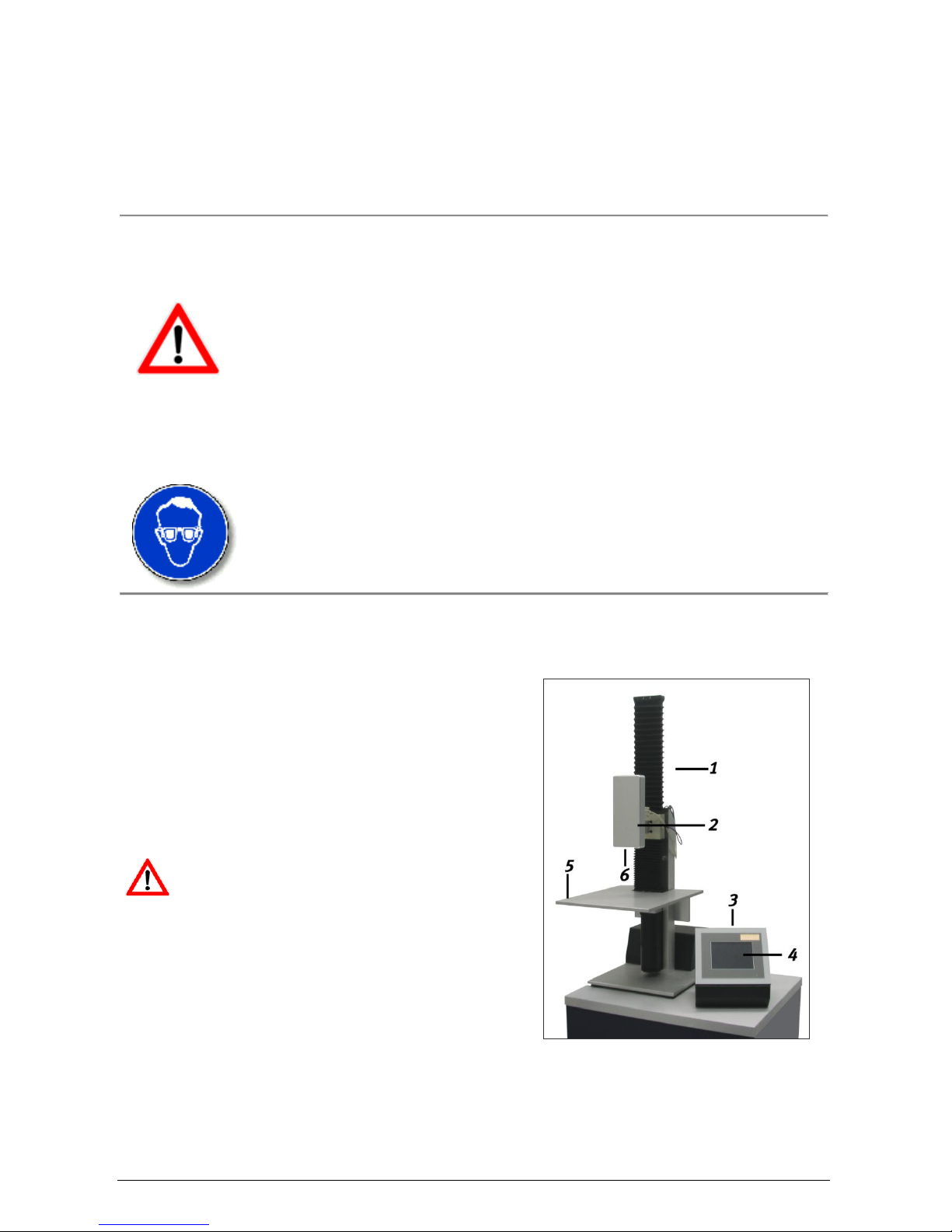
2.0 OVERVIEW OVER THE COMPONENTS AND THE INITIATION ..................................................................3
3.0 ENGAGING THE INSTRUMENT AND PREPARATING THE MEASURMENT.............................................4
4.0 MENUSTRUCTURE, FUNCTIONS, SIMBOLS AND GENERAL HANDLING................................................5
4.1 MENUSTRUCTURE ..................................................................................................................................................5
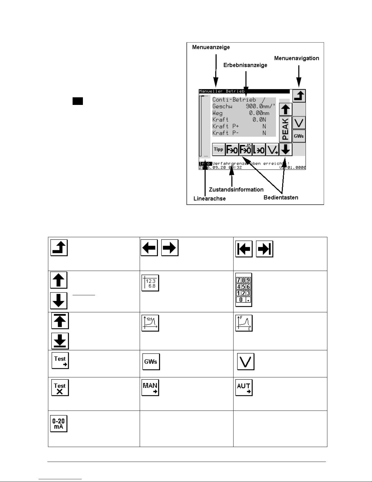
4.2 GENERAL OPERATING ADVICES AND SYMBOLS..........................................................................................5
4.2.1 NAVIGATIONBUTTONS FOR OAGING AND CHANGE OF THE LEVEL OF THE MENU ............................6
4.2.2. HANDLING ARROWS TO CONTROL THE TEST STAND.................................................................................7
5.0 MODE OF OPERATION ...........................................................................................................................................7
5.1 EXPLANATION OF INSTRUMENTATION.............................................................................................................................................................7
5.1.1 FORCE MEASURMENT........................................................................................................................................7
5.1.2 PATH MEASURMENT...........................................................................................................................................8
5.1.3 DISCONNECT CONDITIONS / LIMITS 8
5.2. MANUAL MODE.......................................................................................................................................................8
5.2.1 REGULATION OF THE SPEED LEVELS...........................................................................................................8
5.2.2 REGULATION OF THE LIMITS......................................................................................................................................................................................9
5.2.3 CONTINUOUS MODE (CONTI) ...........................................................................................................................9
5.2.4 RIDE IN THE TIPP-MODE (TIPP).......................................................................................................................9
5.2.5 INDICATION AND RESET OF THE PEAK VALUES ( MAXIMUM VALUES)............................................9
5.2.6 TARE THE FORCE AND PATH INDICATION................................................................................................10
5.3. AUTOMATICAL MODE WITH PREDEFINED INSPECTION PROCESSES ...............................................10
5.3.1 GENERAL ..............................................................................................................................................................10
5.3.2. DEFINITION OF THE VALVE POSITION......................................................................................................10
5.3.3 PREDEFINED FUNCTIONS................................................................................................................................10
5.3.3.1 ZERO-POINT-SEARCH ...........................................................................................................................................................................................11
5.3.3.2 BREAKDETECTION................................................................................................................................................................................................11
5.3.3.3 FORCE REGULATION .............................................................................................................................................................................................11
5.3.3.4 PATH REGULATION ...............................................................................................................................................................................................11
5.3.3.6 HARDNESSGRADE.................................................................................................................................................................................................11
5.3.4 PREDEFINED TEST PROGRAMMS .................................................................................................................12
5.3.4.1 BREAK TESTING 1-DIAGRAMM ............................................................................................................................................................................13
5.3.4.2 BREAK TESTING 2–PEAK VALUES .......................................................................................................................................................................13
5.3.4.3 BEND TESTING –PATH DEPENDING .......................................................................................................................................................................14
5.3.4.4 ENDURANCE TESTING (PRESSURE)WITH PRESSURE-FORCE-REGULATION ............................................................................................................15
5.3.4.5 TOW TESTING 1-DIAGRAMM ...............................................................................................................................................................................16
5.3.4.6 TOW TESTING 2–PEAK VALUES...........................................................................................................................................................................16
5.3.4.7 STRECH TESTING –PATH DEPENDING....................................................................................................................................................................17
5.3.4.8 ENDURANCE TESTING WITH TENSION FORCE REGULATION ...................................................................................................................................18
5.3.5 CLIENT-SPECIFIC/CUSTOM DESIGNED INSPECTION PROCESSES.....................................................18
6.0 SERVICE FUNCTIONS..........................................................................................................................................19
6.1 BASIC SETTINGS....................................................................................................................................................19
6.1.1 LANGUAGE ...........................................................................................................................................................19
6.1.2 PASSWORD............................................................................................................................................................19
6.1.3 PATH AND SPEED BASE PLATE......................................................................................................................19
6.2. CALIBRATION........................................................................................................................................................20
6.2.1 CALIBRATION OF THE LOAD CELL..............................................................................................................20
6.2.2 PATH CALIBRATION..........................................................................................................................................20
6.3. ADJUST DATE AND TIME ...................................................................................................................................21
6.4. REPORT-MEMORY ...............................................................................................................................................21
6.5. CANCELING THE RESULT-MEMORY .............................................................................................................21
8.0 TECHNICAL DATA.................................................................................................................................................22
7.0 CONNECTION TO THE PC ...................................................................................................................................21
9.0 MAINTENANCE.......................................................................................................................................................22
9.1 LINEAR BEARING..................................................................................................................................................22
9.2 UPDATES (SOFTWARE) ........................................................................................................................................22
9.3. CHANGE COMPONENTS .....................................................................................................................................23
10.0TROUBLESHOOTING...........................................................................................................................................23
11.0 WARRANTY ...........................................................................................................................................................23
12.0 PRODUCT REGISTRATION................................................................................................................................23

3
Thank you for choosing our universal test stand FMT-310. Please read the entire operation manual
thoroughly before using this instrument for the first time. The information contained here will help you
to achieve accurate and reproducible results and to avoid misuse or damages.
This FMT-310 Force Tester is designed to apply material testing and to acquire load-displacement-
diagrams within fixed load and displacement limits. To control the fitness for use of the test stand for
your special case of use, get if necessary into contact with our technical service.
1.0 Safety Precautions
Please note, that the max. admissible force values of the load cell and of the linear
drive with step motor can be different.
The load cell can be damaged by an overload of the measuring axle. Do not apply
side or radial forces to the rigid measuring axle. Please note the advices during the
assembly of tools.
Operate the instrument in appropriate environments only. The instrument is
equipped with a temperature compensation for 0°….40°C. Use the instrument in
this temperature range only.
If you effect a material testing during which the material can break or sliver in a
way that people, the test stand or other instruments in the near could get
damaged, you have to install protective equipment. If you have no protective
equipment at your disposal, we would be glad to help you out.
2.0 Overview over the components and the initiation
The FMT-310 Force Tester consists of two base units, the motorised test stand (1) with integrated load
cell (2) and the control unit (3) with touchpanel (4) for the
operation. The dependence of the application area, different
tools can be assembled on the specimen stage (5) and /or
the axle of the load cell (6).
Please check that the load cell stands at any position
between the two limits (7) before initiating the instrument. If
this shouldn’t be the case, it is possible to displace the load
cell manually as long as the test stand is not switched on.
Attention! If the test stand gets initiated without
the load cell standing between the limits, it can
effect a damage of the linear unit.

4
Connect now the control unit with the test stand by inserting and
locking the 37-pol connector (11).
Check if the two plug connections (9;10) for the position sensor (8)
and the load cell are inserted.
Connect now the power cable (12)
and switch on the instrument. The
lamp within the switch gleams red
when the instrument gets energized.
Check if necessary if the emergency
stop switch is pressed.
3.0 Engaging the instrument and preparing the measurement.
After switching on the instrument at the main switch,
you can see the start picture in the display. At the same
time an automatic function test takes place and the
force gauge gets initiated. After this test has been
finished succesfully, the change to the main menu
takes place.
Press now the button REF, it takes place an
automatic adjustment of the internal zero
reference (machine-zero). For this the load
cell gets driven into the highest position. After the
reference path has been effected succesfully, the test
stand is ready for use. Now you can choose the
wanted function within the main menu.
In dependence of the application different tools get assembled on the measuring axle and onto the
specimen stage. In case that these tools have been assembled in factory, the limits (limit of way) are
already adjusted.
Attention! In case that you use your own tools and/or effect the initiation without the help of
our technical service, please effect an assimilation of the limits within the service menu to
avoid collisions and by this damages on the test stand.

5
4.0 Menustructure, functions, symbols and general handling
The menu of the control is structured in a way that allows to return to the subordinated menu at any
time by pressing the BACK-button (right above). You choose a submenu by pressing the appropriate
button. Within a submenus there can be other options and other possibilities to parameterize.
4.1 Menustructure
Start picture
Main menu
Manual mode
Set limits
Set speed levels
Automatic mode
Range of inspection processes
Break testing 1 –Diagram Settings
Results Diagram
Break testing 2 - Diagram Setting
Results
Bend testing –Path depending Settings
Results Diagram
Endurance testing - Force regulationSettings
Results Diagram
Tow testing 1 - Path depending Settings
Results Diagram
Tow testing 2 –Peak Settings
Results
Stretch testing 1 –Path depending Settings
Results Diagram
Stretch testing 2 –Force regulation Settings
Results Diagram
Service
adjust date/time
report-memory
calibration (Force and path)
basic settings
Reference path
4.2 General operating advices and symbols
The appliance of the test stand takes place with the help of the buttons onto the screen of the control
unit. Thereby the buttons can be changed, blocked or released in dependence of the menu and the
operating state.

6
As far as possible, the arrangement of the buttons on the screen is identically. Consecutively the
general construction is outlined:
The headline gives the titel of the actually
retrieved menu. In the footer date, time and the
memory capacity (depending on the menu) and
the number of the version get indicated. The
greeting Info gives information about the actual
situation. The navigation bar is placed at the right
border of the screen. It allows to retrieve
submenus, the change of higher menu levels and
the change of settings. At the left border of the
screen the position of the slide and the current
limit settings are indicated. Below and to the right
of the result indication are the buttons for the
handling of the instrument.
4.2.1 Navigationbuttons for oaging and change of the level of the menu
Back
Leaves the actual menu and
turns back to the next higher
level of menu
Scroll back and
forth
The arrow keys right/left
allow to scroll back and forth between
different pages of the same level of menu.
Jump to the
first/last page
The arrow keys allow to
jump to the first/last pager of the same level
of menu.
Scroll
To jump line by line within the list
of parameters or results.
ATTENTION: within the manual
mode the arrows indicate only
the movement of the slide per
direction!
List of parameter
After pressing the button appearce
a list of parameteriseable
settings.
Enter - keyboard
By pressing the button the input
box to change the
parameterizeable settings
appearse.
Jump first/last line
The arrow keys allow to jump to
the firs/last record of results of
the same level.
Result menu
By pressing the button a change
into the submenu takes place. The
results of the chosen inspection
process get indicated in the form of a table.
Diagramm
Within the result menu it is
possible to indicate results in
dependence of the inspection
procesws in form of a diagramm.
Testprogramm
Change of the testprogramm
within an inspection process.
Limits
Limit settings for path/force
within the manual mode.
Speed
Setting of the speed levels for the
manual mode.
Testprogramm
Erase of the selected test-
program within an inspection
process.
Jump to MAN
Direct jump from the parameter –
settings of an inspection process
to the MAN area for getting way parameters.
Jump to AUTO
Direct jump from the MAN –area
back to the parameter –setting of
an inspection process.
Analog signals
Input area for setting the external
analog signals.

7
4.2.2. Handling arrows to control the test stand
Guide
To guide upwards or downwards
within the manual mode.
ATTENTION: The same arrows, at
the right boarder of the screen,
serve for the menu navigation.
Start or Stop
arrow
To initiate, abort or stopp
the test run within the
manual mode.
Acknowledgement key
By pressing this key you
acknowledge the indicated
process.
Abortion key
By pressing the abbortion key the
effection of the chosen process
gets distorted or aborted.
Conti-mode
Change from the Tipp to the
Conti mode
Tipp-mode
Change from the Conti to the Tipp
mode
Readout of the peak
values
By pressing the button the
currently in the force gauge saved
values of pressure and tensione
force values get indicated.
Next cycle
By pressing the next go of an
inspection process with various
cycles gets started.
Speed levels
Change between the 5 setted
speed levels within the manual
mode.
Zero setting force
Removing the measured force
value on 0
Cancel the paek values
Canceling the peak values within
the force gauge.
Zero setting path
Removing the measured
wegelinals on 0.
5.0 Mode of operation
5.1 Explanation of instrumentation
5.1.1 Force measurement
For the force measurement, high-precision measuring beam get used, their deflection during force
transmission gets recorded by a extension-measuring tape. The conversion of the analog signals into
digital form takes places within the load cell. The digital signals of the D/A –converter constitutes 1000
Hz., the transfer rate to the control unit 100 Hz.
The load cell gets imported and tared with every restart of the universal testing machine.
Contemporaerly a temperature compensation takes place. Fluctuation of temperature during the
operation of the test stand lead to errors of measurement (TK=0,02%K). If more intense changes of the
environmental conditions take place during a working day, it is recommendable to switch on and off
again the instrument to adjust the load cell to the compensation of the changed environmental
conditions.
The load cell should be checked at regular intervals. Accordant to DIN ISO 75000 a calibration is
necessary after 12 month, after repairation or after lager backfittings. A change of the load cell, if it has
been effected duly, does not demand a calibration or adjusting.
The calibration (adjusting) of the load cell is simple user effectable within the service- program (see
chapter 6.2.).

8
5.1.2 Path measurement
The whole traverse path (405mm) of the drive gets suspended in 1.687.500 steps. This corresponds to
an intern resolution of 0,24µm, the change of the position in single steps gets indicated with a
resolution of 0,01mm. As both the load cell and the machine itself get expanded or compressed under
load, the absolute traverse deviates from the actual path on the measuring axle. To compensate this
error, the indicated path gets corrected with a force depending factor. Before the purchase of the
instrument, the correction factor gets appraised and setted by the manufacturer. The correction factor is
simple user appraisable and can be saved within the instrument.
A calibration (adjusting) should be effected after changing the force gauge as only theoratical values get
get adopted into the control unit during the initiation of the force gauge. The calibration takes place in
the service menu. (see chapter 6.2).
5.1.3 Disconnect conditions / Limits
Indipendent of the mechanical structur of the universal test stand and the force gauge, for which limits
get deposited before commissioning the instrument, it is possible to deposit universally valid limits for
path and force, as protection of checking tools and of material, which is to control. When these values
get achieved, the inspection process gets aborted and an infotext-display takes place in the lower line
of the display.
The load cells have an additional electronic overload protection which takes effect, independently of
the setted limits, as soon as a damage of the load cell is imminent. The control unit tries automatically
to take it off into the diametrical direction with a propulsion command.
Similarly the drive does not allow to cross the mechanical boarders which are predetermined by the
cursors, as they effect a emergency-stop.
Whenever an emergency-stop has been effected or the test stand does not allow any manual propulsion
because of overlapping limits, the test stand has to be turned currentless. In this condition the retention
force of the motor gets lifted and the load cell can be pushed to any position between the two cursors.
5.2. Manual mode
In the manual mode you can move the load cell
with a preselected speed within the
predetermined limits upwards or downwards by
pressing the appropriate buttons. The current
reading and the current running speed are
indicated on the screen.
5.2.1 Regulation of the speed levels
In the manual mode up to 5 different speed levels can be chosen by pressing the key V>. The speed
levels 1 to 5 can be regulated within the therefore intended submenus. The submenu gets called by
pressing the key Vset . Than you can choose the speed level you’d like to edit and enter the approriate
speed. When you leave the submenu, the speed levels get changed corrispondingly.

9
5.2.2 Regulation of the limits
The traverse path of the load cell can be limited
within the machine and load cell determined
maximum values. Therefore the submenu limits
gets called in which you can regulate the values
within the navigation bar.
Advice !
i The limits regulated for the manual mode have no influence within the test programs. The drive
gets stopped with a certain speed depending profile after achieving the limits or the Stop-signal by
pressing the stop-button or letting go the up-/down button. At maximum speed the lag can constitute
2mm.
5.2.3 Continous mode (Conti)
Within the continuous mode you can start the drive by pressing the up or down-button in the required
direction. The drive moves the load cell in the required direction till either the Stop-button gets pressed
or a limit gets achieved.
5.2.4 Ride in the Tipp-mode (Tipp)
In the tip-mode, which gets setted by the mode-button, the drive gets moved with a preselected speed
into the required direction, till the button gets released or a limit gets achieved.
5.2.5 Indication and reset of the peak values ( maximum values)
The absolut maximum values for traction force and compression force get saved within the load cell.
The two maximum values reached at last, get indicated after pressing the PEAK –button. The peak-
memory gets only canceled in the manual mode, when the reset-button is pressed, a test program gets
called, and a reference path has been effected or the construction was spent.
Parameter
Permissible range of values
Reference
Min.
Max.
Limits position DOWN
SP top
405,00mm
Absolute on 0-reference
Limits position TOP
0,00mm
405,00mm
Absolute on 0-reference
Limits force PRESSURE
0 N
Nominal frequency range of the
load cell
110% range of measurment
Limits force TENSIONE
0 N
Nominal frequency range of the
load cell
110% range of measurment

10
5.2.6 Tare the force and path indication
All indicated values can be reset to 0 during stillstand of the drive. Thereby the internal data of the load
cell and absolute position of the linear unit do not get tared. Therefore a reference path has to be
effected.
5.3. Automatical mode with predefined inspection processes
5.3.1 general
With inspection process are ment motion sequences (program steps) which get effected typically for a
test. Every inspection process can include up to 30 single steps. It’s possible to save a total of 16
inspection processes within the control unit, as standard 8 inspection processes are deposited.
In every inspection process various parameter for a test program can be insert individuelly to effect
adjustments on the material, which has to be checked and tools in use. For every inspection process it
is possible to deposite up to 8 different parameter sets as test programms.
As maximum up to 128 parameterized test programms can be deposited within the control unit.
The parameter have to be insert for every test programm in dependence of th load cell in use, the tools
in use and the respective test object. First of all, reasonable values for a test get usually averaged out
within the manual mode. While changing the load cell all parameter sets in all test programms get reset
onto the default values to avoid possible damage on the construction. If you change the tools in use or
the material to check, it might be necessary to adjust the parameter to avoid damages on the
construction.
The submenu to regular the parameter gets called by pressing the parameter button.
5.3.2. Definition of the valve position
Reference position absolut position in which the load cell gets driven during the referencing of the
drive. (Masch.null). All other position refer to this absolut set point.
Setpoint TOP Absolut upper position in which the load cell can be driven during the operation.
As maximum this position comes up to the reference position. (Default =
0,00mm)
Setpoint DOWN Absolut low position in which the load cell can be driven. As maximum this
position comes up to the maximum traverse pathof the drive. (Default =
405,00mm)
HOME position Absolute position in which the load cell gets driven before and after a test rum to
have the possibility to in insert the test object.
Position START Absolute position in which the load cell gets driven before a test run starts. Unit
drives from the HOME position into the START position.
Zero-position Relative position in which the measurment of length gets tared in dependence of
other measures (0-point of measurment)
5.3.3 Predefined functions
Some propulsion commands or subroutines, which again and again are necessary are deposited as
functionsblocks.

11
5.3.3.1 Zero-Point-Search
During the zero-point search the reletive zero points of the force measurment and the path measurment
get sincronized. Herefore the load cell gets moved with a predefined speed till the adjacent force value
exceeds 0,5 % of the par value of the load cell. After this the load cell gets driven back to the force-zero-
point with a predefined speed and the path measurment gets tared. The driving speeds get setted
automatically and depend on the load cell in use and the hardnessgrade of the material.
5.3.3.2 Breakdetection
During destructive inspection processes the fall of force after breaking or jerking of the material gets
recorded, the movement stoped and the force gauge gets driven back into the home position. The
breakdetection gets activated when the actual force F exceeds the adjusted %-value, refered to the
nominal range of measurment of the inserted range of force measurment. After that the load cell drives
on with the speed V<Break> and thereby the maximal force value gets averaged out continously. Does
the current force value fall down to a preregulated %-set of the maximal forcevalue, the ride gets stoped
and the linear drive brings the load cell back into the home-position.
5.3.3.3 Force regulation
During the forceregulation a predefined force gets kept for kept for a predefined amount of time. The
drive re-enacts automatically the position of the load cell, provided that the material property demands
this. The basic and the driving speed depends of the regulated hardnessgrade of the material. Is the
hardnessgrade understated it can lead to a consequently overshooting of the regulation. Is the
hardnessgrade overstated, the defined value of force will not be achieved within an appropriate amount
of time.
5.3.3.4 Path regulation
During the path regulation a path, predefined within the inspection proceses, does not refer to the
linearantrieb but to the compensated positionof the lead. The position of the slide gets corected until
the predefined way on the measuring object is achieved.
5.3.3.6 Hardnessgrade
As the universal test stand can be used both for very hard and prim materials and for soft or elastic
material, for the optimal force/path regulation the hardnessgrade of the material has to be established.
rials vorgegeben werden. In dependence of the load cell in use, the hardnessgrade defines the
travelling speed during the 0-point search and the force regulation.
Attention! Is the hardnessgrade regulated too low, it can lead to unwished early distruction while using
a refractory material or to an overshooting of the regulation while using a flexible and elastical material.
Hardnessgrade 0...99 0 stands fo a very soft material,
and 99 for a very hard, refractory material.

12
5.3.4 Predefined test programms
During a test run the relevant dates are indicated on the display. After the test has been finished, the
stored values can be called with the help of the
result-button. If the test procedure effects a
diagramm record, too, the force/path curve of the
list of readings can be indicated by the help of the
diagramm-button.
Substantially the way of representation is equal in all test runs. To effect a detailed representation of
the measured values, it is possible to change the diagramm representation by the help of the following
buttons.
Enlarge y-axle with
readings of
measurment of force
Minimise y-axle with
readings of
measurment of force
Enlarge x-axle with
readings of
measurment of
length
Minimise x-axle with
readings of
measurment of
length
The recorded force values are placed on the y-axle, the corrisponding position values on the x-axle. The
scaling of the diagram takes automatically place on the base of the size of the values and the nuber of
recorded readings. Due to the size of the display the representation of measurment results is limited.
For an advanced evaluatio it is advisable to import the dates into MsExcel with the help of the download
–programm FMT-Connect (Art. Nr. FMT-972S) and to them up there.
To be able to work with the predefined test procedures, the parameter for the corrisponding test
programm have to be setted.

13
5.3.4.1 Break testing 1 - diagramm
The test procedure serve to appraise the breaking force by pressing continuously at a uniform speed the
measurment object, while the readings get recorded continuously with a frequenz of 100Hz and than
saved in the result memory. The operation consists of following steps:
1. Research of the HOME position at the speed vHome;
2. Movement with the speed vHome up to the position START directly above the object;
3. O-Point research specimen;
4. Start of the measurment by movement downward at the speed vStart;
5. Start of the bread detection at x% of the nom.force of the load cell;
6. Ride up to bread with the speed V<Bruch>.
7. End of measurment at x% of the maximum force value and return to the home-position.
8. Indication of the peak value at the position of the break.
9. Test seies in the reading memory.
Adjustable parameter for the test procedure “ Break testing 1 – Diagramm”
Parameter
Permissible range of values
Reference
Min.
Max.
Setpont position DOWN
SP top
405,00mm
Absolut on 0-Reference
Setpoint position TOP
0,00mm
405,00mm
Absolut on 0-Reference
Setpoint force PRESSURE
0 N
Nominal-range of load cell
Setpoint force TENSION
0 N
Nominal-range of load cell
HO;E position
SP top
SP down
Absolut on 0-Reference
Spee vHome
0,1 mm/min
900,0 mm/min
Hardnessgrade measurment
object
0
99
START position
HOME position
405,00
Speed bread detection
0,1 mm/min
900,0 mm/min
Force % Breakdetection
0,00 %
100%
Speed till break
0,1 mm/min
900,0 mm/min
Force % break
0,00 %
100%
5.3.4.2 Break testing 2 –Peak values
The inspection process serves to appraise the breaking force at various successive tests by pressing
continuously at a uniform speed the measurment object, while the readings get recorded at the
moment of the break and than saved in the result memory. The operation is indentical with the one of
breaking test 1, only that the measurment values in the moment of the break get recorded and the
number of test cycles (number of specimen) is predefined.
Adjustable parameter for the test procedure “Break testing 1 – Diagramm”
Parameter
Permissible range of values
Reference
Min.
Max.
Setpoint position DOWN
SP top
405,00mm
Absolut on 0-Reference
Setpoint position TOP
0,00mm
405,00mm
Absolut on 0-Reference
Setpoint force PRESSURE
0 N
Nominal-range of load cell
Setpoint force TENSION
0 N
Nominal-range of load cell
HOME position
SP top
SP down
Absolut on 0-Reference
Speed vHome
0,1 mm/min
900,0 mm/min
Hardnessgrade measurment
object
0
99
Number test –cicles
1
1000
START position
HOME position
405,00
Speed VStart
0,1 mm/min
900,0 mm/min
Force % Breakdetection
0,00 %
100%
Speed till break
0,1 mm/min
900,0 mm/min
Force % break
0,00 %
100%

14
5.3.4.3 Bend testing –path depending
The test programm serves to appraise the necessary pressure force at a uniform speed and a predefined
stretch of way.
1. Research of the HOME position at the speed
vHome;
2. Movement with the speed vHomeup to the position START directly above the object;
3. 0-point search specimen;
4. Zero-setting of path/force (0-position test gets new setted) and peak values get reset;
5. Start of reading collection and displacement of the force gauge, the path is predetermined;
setted speed <Weg> ( ATTEND prefix of the way-value !! )
6. After acchieving the the target position, pause for time T, predetermined;
7. Return for the path_2 absolut relating to 0-position test ( ATTEND prefix of the way-value !! );
8. Switch-off of the test serie force and path;
9. Automatically the slide gets moved upwards with the speed vHome to the HOME position;
Adjustable parameter for the test procedure “Bend testing – path dependend”
Parameter
Permissible range of values
Reference
Min.
Max.
Setpoint position DOWN
SP top
405,00mm
Absolut on 0-Reference
Setpoint position TOP
0,00mm
405,00mm
Absolut on 0-Reference
Setpoint force PRESSURE
0 N
Nominal-range of load cell
Setpoint force TENSION
0 N
Nominal-range of load cell
HOME position
SP top
SP down
Absolut on 0-Reference
Speed vHome
0,1 mm/min
900,0 mm/min
Hardnessgrade measurment
object
0
99
START position
HOME position
405,00
Path_1 +/- S relativ
-100,00mm
100,00mm
+ => pull under
- => upstairs
Speed path
0,1 mm/min
900,0 mm/min
Time T PAUSE
0 s
9999 s
Force till FSB
0 N
Nominal-range of load cell
Path_2 +/- S relativ
-100,00mm
100,00mm
+ => pull under
- => upstairs
Speed path
0,1 mm/min
900,0 mm/min
Time T PAUSE
0 s
9999 s
Force till FSB
0 N
Nominal-range of load cell

15
5.3.4.4 Endurance testing (Pressure) with pressure-force-regulation
The measurment object gets comprimied with the help of the inspection process. Herefore a
forceregulation gets switched on after the excess of a predetermined force. This regulation maintains
the force value for a predetermined time, if neseccary by changing the position of the force gauge.
1. Research of the HOME position with the speed
vHome;
2. Movement with ths speed vHome up to the position START directly above the object;
3. 0-point-search and zero-setting of path/force (0-position check gets new setted), reset of peak
values
4. Start of reading record;
5. Movement with the predetermined speed until achievement of a predetermined force border;
6. Engaging of the force regulation and movement of the load cell until achieving the holding force;
Remaining for the predetermined pause time after the first arrival at the holding force.
7. End of the reading record and ride to the Home positionsition.
Adjustable parameter for the test procedure “ Load –force regulated”:
Parameter
Permissible range of values
Reference
Min.
Max.
Setpoint position DOWN
SP top
405,00mm
Absolut on 0-Reference
Setpoint position TOP
0,00mm
405,00mm
Absolut on 0-Reference
Setpoint force PRESSURE
0 N
Nominal-range of load cell
Setpoint force TENSION
0 N
Nominal-range of load cell
HOME position
SP down
SP down
Absolut on 0-Reference
Speed vHome
0,1 mm/min
900,0 mm/min
Hardnessgrade of measurment
object
0
99
START position
HOME position
405,00
Force F0
0 N
Nominal-range of load cell
Speed vFo
0,1 mm/min
900,0 mm/min
Force PAUSE
0 N
Nominal-range of load cell
Time PAUSE
0 s
9999 s

16
5.3.4.5 Tow testing 1 - Diagramm
The inspection process serves to appraise the tear-out force at a continuous tension at a uniform speed
until the break of the measurment object. Substantially the single steps corrispond with the break
testing 1. For tambling the samle there is another intermediate Stepp in which the force gauge can be
positionated manually. Therefor the upwards/downwards buttons get activated until the procedure gets
continued by confirming with the OK-button.
Adjustable parameter for the test procedure „ tow testing 1 – Diagramm”
Parameter
Permissible range of values
Reference
Min.
Max.
Setpoint position DOWN
SP top
405,00mm
Absolut on 0-Reference
Setpoint position TOP
0,00mm
405,00mm
Absolut on 0-Reference
Setpoint force PRESSURE
0 N
Nominal-range of load cell
Setpoint force TENSION
0 N
Nominal-range of load cell
HOME position
SP top
SP down
Absolut on 0-Reference
Speed vHome
0,1 mm/min
900,0 mm/min
Hardnessgrade measurment
object
0
99
Speed vTIipp
0,1 mm/min
900,0 mm/min
Speed VStart
0,1 mm/min
900,0 mm/min
Force % Break detection
0,00 %
100%
Speed break
0,1 mm/min
900,0 mm/min
Force % break
0,00 %
100%
5.3.4.6 Tow testing 2 –Peak values
Like the former one, the inspection process serves to appraise the tear-out force at a continuous tension
at a uniform speed until the break of the measurment. Instead of a test serie the peak values and
position of the measurment object at the moment of the break get recorded. The number of
measurment objects that have to be testet successional is predetermined as number of cycles.
Adjustable parameter for the test procedure „Tow testing 2 –Peakvalues”
Parameter
Permissible range of values
Reference
Min.
Max.
Setpoint position DOWN
SP top
405,00mm
Absolut on 0-Reference
Setpoint position TOP
0,00mm
405,00mm
Absolut on 0-Reference
Setpoint force PRESSURE
0 N
Nominal-range of load cell
Setpoint force TENSION
0 N
Nominal-range of load cell
HOME position
SP top
SP DOWN
Absolut on 0-Reference
Speed vHome
0,1 mm/min
900,0 mm/min
Hardnessgrade measurment
object
0
99
Speed vTipp
0,1 mm/min
900,0 mm/min
Number test cycles
1
1000
Speed VStrat
0,1 mm/min
900,0 mm/min
Force % Breakdetection
0,00 %
100%
Speed brek
0,1 mm/min
900,0 mm/min
Force % break
0,00 %
100%

17
5.3.4.7 Strech testing –path depending
With the help of the Inspection process it’s possible to calculate the necessary tension force to effect a
the predetermined elongation of a measurement object at a constant speed. Hereby the measurement
values get recorded with a measurement range of 100 hz.
1. Research of the position HOME with the speed vHome;
2. Plamping of the specimen, in the tipp mode the load cell can be moved upwards or downwards
with the tipp speed vTipp until the automatical test run gets continued after confirmation.
3. O-Point-searc specimen with zero- setting of path/force (0-position check gets new setted) and
reset of the peak values;
4. Beginn of reading record and ride with predetermined speed until acchieving the predetermined
path_1 ( ATTEND prefix of the way-value !! );
5. Stop of drive and pause for the pause time T;
6. Return for the path_2 absolut relating to 0-position test ( ATTEND prefix of the way-value !! );
7. End of the reading record and return to the HOME position.
Adjustable parameter for the test procedure “Strech testing – path depending”
Parameter
Permissible range of values
Reference
Min.
Max.
Setpoint position DOWN
SP top
405,00mm
Absolut on 0-Reference
Setpoint position TOP
0,00mm
405,00mm
Absolut on 0-Reference
Setpoint force PRESSURE
0 N
Nominal-range of load cell
Ssetpoint force TENSION
0 N
Nominal-range of load cell
HOME position
SP top
GW unten
Absolut on 0-Reference
Speed vHome
0,1 mm/min
900,0 mm/min
Hardnessgrade mearsurment
object
0
99
Speed vTIPP
0,1 mm/min
900,0 mm/min
Path_1 +/- S relativ
-100,00mm
100,00mm
+ => pull under
- => upstairs
Speed path
0,1 mm/min
900,0 mm/min
Time T PAUSE
0 s
9999 s
Force till FSB
0 N
Nominal-range of load cell
Path_2 +/- S relativ
-100,00mm
100,00mm
+ => pull under
- => upstairs
Speed path
0,1 mm/min
900,0 mm/min
Time T PAUSE
0 s
9999 s
Force till FSB
0 N
Nominal-range of load cell

18
5.3.4.8 Endurance testing with tension force regulation
Substantially the inspection process corrisponds with the endurance testing with pressure force
regulation. But for an easier clamping, a manual intermedia Stepp is inserted.
Adjustable parameter for the test procedure
5.3.5 Client-specific/custom designed inspection processes
Next to the previous described inspection processes, it’s possible that other client specific of custom
designed inspection processes are deposit, too. The description of the operation may be described
within the enclosure 1.
Parameter
Zulässiger Wertebereich
Reference
Min.
Max.
Setpoint position DOWN
SP top
405,00mm
Absolut on 0-Reference
Setpoint position TOP
0,00mm
405,00mm
Absolut on 0-Reference
Setpoint force Pressure
0 N
Nominal-range of load cell
Setpoint force TENSION
0 N
Nominal-range of load cell
HOME position
SP top
SP down
Absolut on 0-Reference
Speed vHome
0,1 mm/min
900,0 mm/min
Hardnessgrade measurment
object
0
99
Speed vTIipp
0,1 mm/min
900,0 mm/min
Force F0
0 N
Nominal-range of load cell
Speed vFo
0,1 mm/min
900,0 mm/min
Force Pause
0 N
Nominal-range of load cell
Time T Pause
0 s
9999 s

19
6.0 Service functions
By service functions are functions ment which usually get used
only during the initiation or during larger changes on the test
stand. You reach the service area out of the main menu by
pressing the service-button,
The submenu shows the fundamental characteristics of
the control, the softwareversion and the data of the last
calibration. Within the info-line you can see the remaining
memory capacity.
All the other menus are protected by a 4-digit administrator-
password. At the moment of delivery it is preallocated with
1234. The user-password is preallocated with 5678. Within the basic settings you can change the
passwords.
6.1 Basic settings
You open the basic settings by pressing the parameter-button and entering the andministrator-
password afterwards.
After that you can edity the basic settings.
6.1.1 Language
you choose the language by setting the corrisponding
parameter. The new chosen language becomes activated after
the next initiation of the instrument.
6.1.2 Password
Categorical the servicefunctions are protected by a password. You can change these passwords and
afterwards not even the Alluris-Service is able to access the servicefunctions without a direct
interference into the firm ware.
It’s possible to protect the parameters for the corrisponding inspection processes with a user-password,
which you can change within the service-menu, too. There you decide, wether the password query is
aktivated (= 1) or deactivated (=0).
6.1.3 Path and speed base plate
The setting of the maximum path of the load cell up to the base plate limits the the settings of the limits
within the manual and the automatical modes. In addition, by this setting the position and the speed,
at which the automatical path calibration and during some automatical inspection processes the search
after the base plate starts, predetermined.
The values should be setted accurately to avoid collisions of the load cell with the base plate or chuck
tools which may be existing and to prevent by this dameges.
German
1
English
2
French
3
Spanish
4
Italian
5

20
6.2. Calibration
Universal testing machines should be calibrated
(or new adjusted) periodally. The herefore
necessary processes are already deposit within the
control. By pressing the calibration-button within the service
menu and the input of the administrator password, the
calibration screem becomes called.
6.2.1 Calibration of the load cell
A calibration of the load cell should be effected periodical, at
least after 12 month. If you prefer not to effect the calibration on your own, our on-site service or our
calibration laboratory is always at your disposal. Please find more informations on www.alluris.de.
Condition for the calibration is a test weight which complies with the international and national
standards so that you can effect the load cell under regard of tools which may have been assembled.
By pressing the force calibration-button, the calibration process gets called.
It doesn’t matter wether you abort the process or effect it till the very end,
afterwards you have to switch of the instrument and it takes about 15 sec.
Till you can switch it on again.
Before initiating the calibration, you need an adapted take-up (hook) for the calibration standard.
Within the first stepp the load cell gets transfered into the calibration mode and the control unit
averages out, which calibration standard can be used for the following process. Within the second
stepp a new 0-adjustment takes place. After this new 0-reference has been setted, the measurment
range of the nominal value gets newly setted by adherencing an adapted reference standard. Only when
the new values have been exactly averaged out and checked on their plausibility within a width, which
is predetermined within the force gauge, the new settings become assumed. Otherwise the old values
remain stored.
After every force calibration it is necessary to switch of the test stand for at least 15 sec., so that the
force gauge can be newly initialised.
6.2.2 Path calibration
The path calibration serves to calculate the correction factor for the real
path onto the measurment object. Because of the elasticity of the system
structure and the real load cell, under force influence the the real path
deviates from the path, which has been effected on the linear unit. As this deviation depands on the
test stand, the load cell and the tools which may be used, it is possible to calculate the correction factor
at any moment.
To effect the path calibration, attach a corrisponding calibration aufs to the measurment axle and put
the face plate on the base plate (calibration tool FMT-810M4/6). After initiating the process, the test
stand drives automatically into a predetermined position above the base plate and than puts the
calibration aufs on the face plate to adjust the 0-point. Afterwardes, the force becomes continuously
developed up to the nominal force. The hereby effected path withing the linear unit becomes recorded.
Afterwards the test stand returns into the reference position. The new calculated values become
deposited within the control and serve to correct the indicated path.
Table of contents
Other Alluris Test Equipment manuals