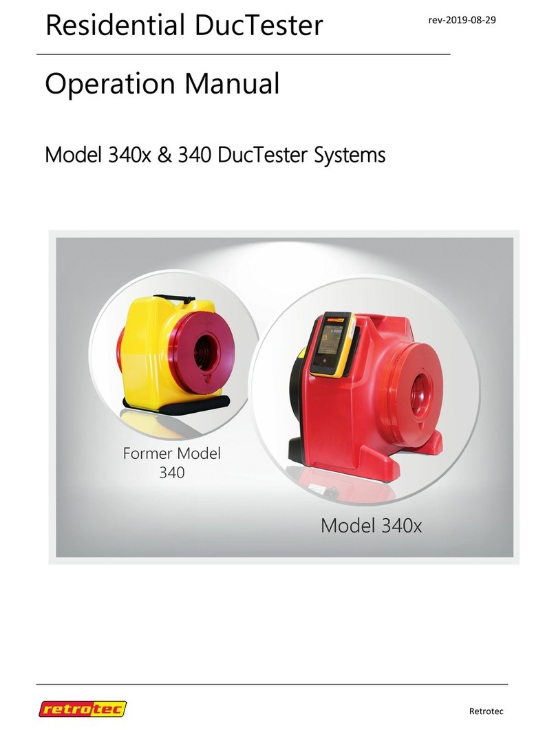
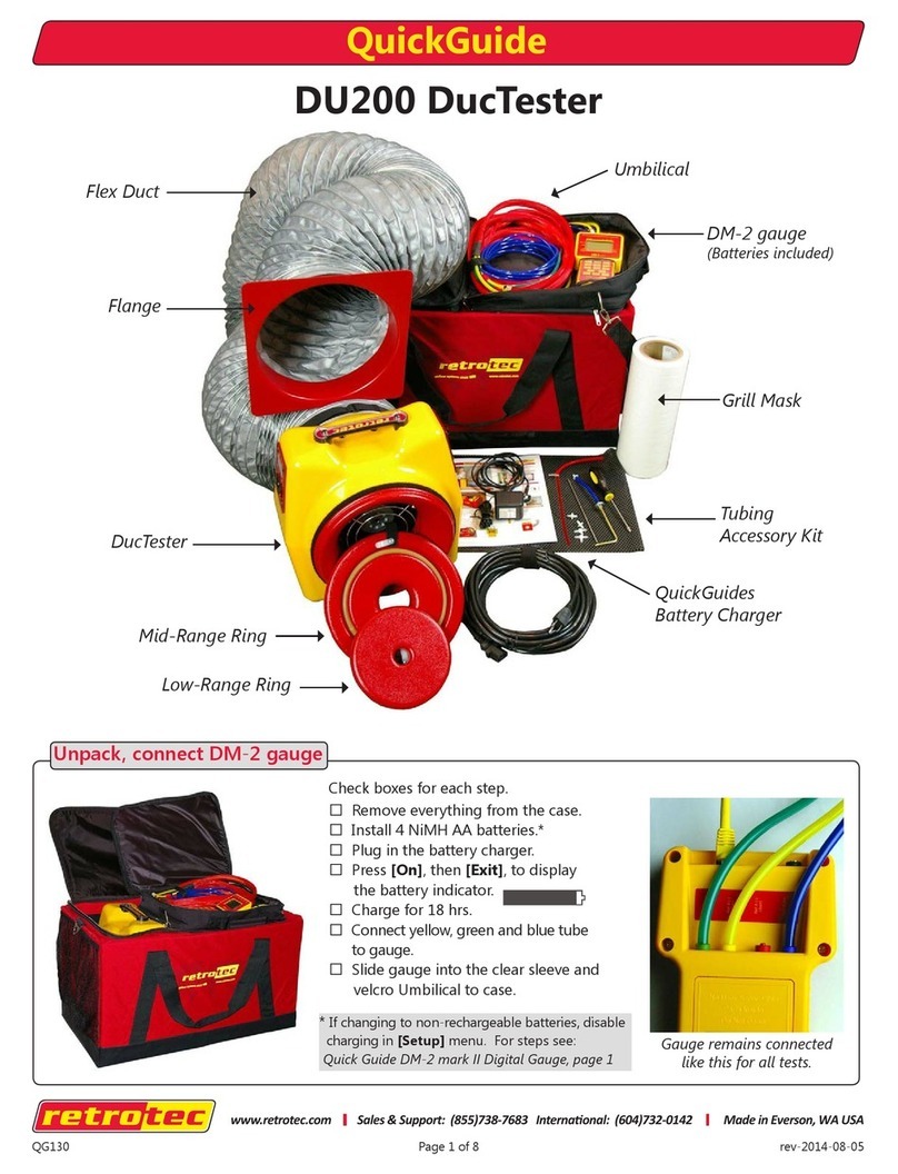
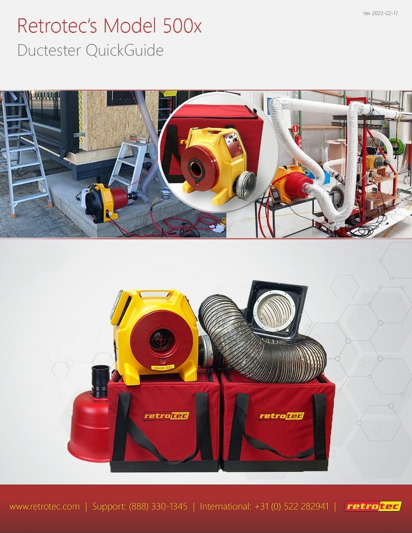
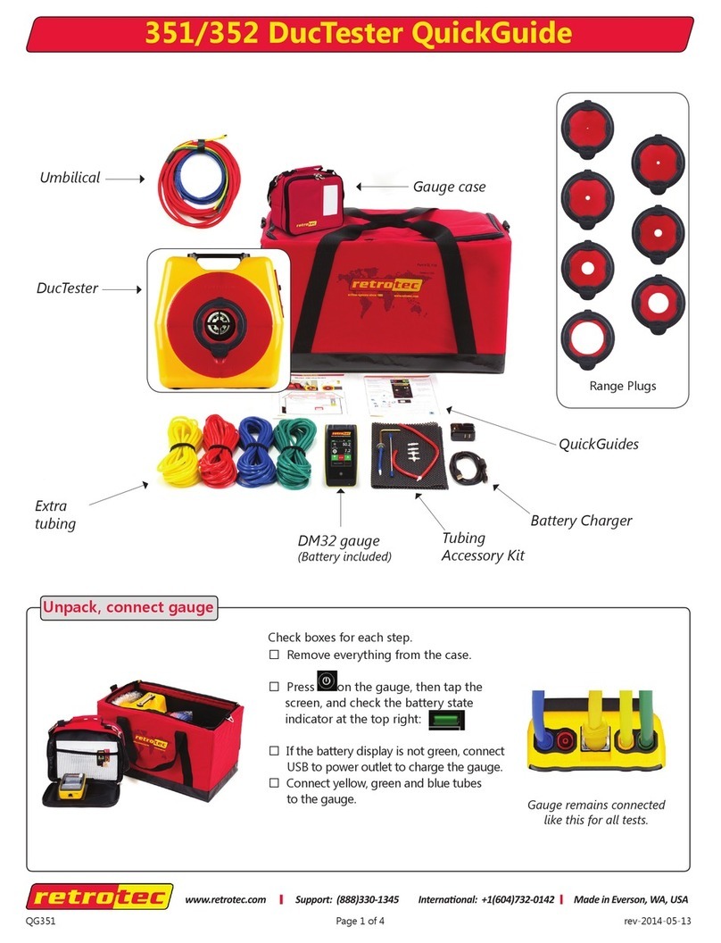
Retrotec DucTester 350x User manual

Retrotec
rev-2020-04-27
Residential DucTester
Operation Manual
Model 350x & 350 DucTester Systems

Page 2 of 58
©Retrotec Inc. 2015
Made by Retrotec Inc.
1060 East Pole Road
Everson, WA USA 98247
For support:
Call 1 (888) 330-1345 in USA
Fax +1 (360) 647-7724
Manual for:
Models 350x with DM32 and Model 350 with DM32 WiFi

Page 3 of 58
©Retrotec Inc. 2015
Copyright © 2014-2019 Retrotec Inc.,
All rights reserved.
This document contains materials protected under International and Federal Copyright Laws. No part of
this book may be reproduced or transmitted in any form or by any means, electronic or mechanical,
including photocopying, recording, or by any information storage and retrieval system without express
written permission from Retrotec Inc.
Retrotec makes no warranties with respect to this documentation and disclaims any implied warranties
of merchantability, quality, or fitness for any particular purpose. The information in this document is
subject to change without notice. Retrotec reserves the right to make revisions to this publication
without obligation to notify any person or entity of any such changes.
DucTester, Infiltrometer, FanTestic are Trademarks of Retrotec Inc. Other trademarks or brand names
mentioned herein are trademarks or registered trademarks of their respective owners.
Retrotec test fans, blower door systems, duct testing systems and gauges have been calibrated in our laboratory
which is accredited by the ANSI-ASQ National Accreditation Board to meet requirements of international standard
ISO/IEC 17025:2005. All pressure and flow devices used in the calibration are traceable to the National Institute of
Standards and Technology and themselves have ISO 17025 accreditation.
Retrotec equipment and software complies with the following standards:
ASTM E779-10, ASTM E-1554, ATTMA TSL1, ATTMA TSL2, CGSB 149.10, DW/143, Energy Star, EN12237, EN13829,
EN15004, FD E51-767, ISO 9972-2015, ISO 14520-2006, NEN2686, NFPA 2001-2015, RESNET, SMACNA-2002, All
USA State Energy Codes, Title 24 and USACE Protocol.
Custom calibration available upon request

Page 4 of 58
©Retrotec Inc. 2015
Table of Contents
Important equipment-related safeguards .......................................................................... 7
Important occupant safeguards during testing ................................................................... 7
1. Why measure Duct Leakage?........................................................................9
1.1 Energy loss ............................................................................................................. 9
1.2 Duct sealing saves money ....................................................................................... 9
1.3 Problems from duct leakage: .................................................................................. 9
2. How much duct leakage is acceptable under existing Codes? .....................10
3. Model 300 / 400 System Types:..................................................................11
4. Types of Duct Leakage Tests.......................................................................12
5. Model 350 DucTesters................................................................................13
Models include 350x and 350 with 4 inch Flex Duct .......................................................... 13
5.1 The calibrated DucTester fan ................................................................................ 13
5.1.1. Range Configurations............................................................................................ 14
5.1.2. Retrotec calibrated fan: Model 300...................................................................... 15
5.2 Digital Gauge........................................................................................................ 17
5.3 Flex Duct .............................................................................................................. 18
5.4 Additional included duct testing components ....................................................... 18
5.4.1. Grill Mask for sealing registers ............................................................................. 18
5.4.2. Umbilical for connecting fan and DM32 gauge .................................................... 18
5.4.3. 10 to 4 inch adapter.............................................................................................. 18
5.4.4. Set of Adapters. .................................................................................................... 19
5.4.5. Toolbag keeps all testing components in one place............................................. 19
5.4.6. Tubing Accessory Kit ............................................................................................. 19
5.4.7. Power Cord ........................................................................................................... 19
5.4.8. 9v Power Supply adapter for charging DM32 gauge............................................ 19
5.4.9. Additional parts and accessories for the DucTester............................................. 20
6. Prepare for the Duct Leakage Test..............................................................21
6.1 Unpack, connect the gauge to the DucTester ........................................................ 21
6.2 Charge the gauge.................................................................................................. 21
6.3 Follow the Quick Guide that came with your system............................................. 21

Page 5 of 58
©Retrotec Inc. 2015
6.4 Prepare the Duct System for a test........................................................................ 22
6.4.1. Before beginning the duct leakage test................................................................ 22
6.5 Make all connections on the gauge and fan........................................................... 22
6.6 Blue Tube location matters when testing leaky ducts............................................ 24
6.7 Connect the DucTester to the Duct System ........................................................... 25
6.7.1. Connect the Flex Duct to return register.............................................................. 25
6.7.2. OR Connect the Flex Duct to the air handler cabinet........................................... 26
6.7.3. OR Connect the Flex Duct to a ceiling level return using a Flow Hood ................ 26
6.8 Install Range Configuration on fan ........................................................................ 26
6.9 Select a test direction ........................................................................................... 27
6.9.1. Setting up for depressurization ............................................................................ 27
6.9.2. Setting up for pressurization ................................................................................ 28
7. Set up the gauge to display Duct Leakage Results.......................................29
7.1 Mode Setup for various standards around the world............................................. 29
7.2 Setting up and using the DM32 gauge for Duct testing .......................................... 30
8. Conduct the Duct Leakage tests..................................................................31
8.1 Total Duct Leakage ............................................................................................... 31
8.2 If no Results are displayed (--)............................................................................... 32
8.3 Cannot achieve test pressure................................................................................ 33
9. Restore the house to pre-test conditions after testing is complete.............34
9.1 Using a smoke puffer............................................................................................ 34
9.2 Using theatrical smoke ......................................................................................... 34
9.3 Using an infrared camera...................................................................................... 34
9.4 Using a wet hand.................................................................................................. 34
9.5 Using a Pressure Pan............................................................................................. 35
10. Measure the Air Handler system flow .....................................................36
10.1 For Code compliance ............................................................................................ 36
10.2 Why measure the Air Handler system flow?.......................................................... 36
10.3 Measure with a DucTester as a powered flow hood on the return......................... 36
10.4 Measure with a DucTester on the air handler cabinet ........................................... 37
10.5 Measure with a gauge and a flow grid................................................................... 37
10.6 Measure using air handler blower curves.............................................................. 38
10.7 Measure using Hole Flow on the gauge................................................................. 38

Page 6 of 58
©Retrotec Inc. 2015
10.8 Measure with a Blower Door attached to the return or cabinet............................. 38
10.9 Other methods ..................................................................................................... 39
11. Field Check the DucTester to find out what is not working......................40
11.1 Field Check the gauge ........................................................................................... 40
11.2 Field Check the DucTester as a system .................................................................. 40
12. Avoid common mistakes .........................................................................42
13. Create a Blower Door with a DucTester fan.............................................43
13.1 Use a DucTester to test tight enclosures................................................................ 43
13.2 Blower Door systems for testing tight enclosures.................................................. 44
Appendix A: Calculate Air Flow based on Channel B Fan Pressure readings......45
Appendix B: Calculate flow if required test pressure cannot be reached..........46
Extrapolation Error for Flow if gauge “n” doesn’t match actual n...................................... 47
Cannot Reach 25 Pa Factors ............................................................................................. 48
Cannot Reach 50 Pa Factors ............................................................................................. 49
Appendix C: Troubleshooting...........................................................................51
“--”appears on display: ................................................................................................... 51
Gauge “Flow” reading does not change? Turn off [@] ...................................................... 51
Fan does not run.............................................................................................................. 51
Checking the DucTester flows .......................................................................................... 51
Adjusting the fan Inlet Nozzle if is rubbing or debris needs to be removed from fan ......... 52
Sealing the 100mm duct with Self-Fusing Silicone Tape .................................................... 52
Appendix D: Using a generator for power ........................................................54
Generators ...................................................................................................................... 55
Honda Generator EU3000 (120V, 2000W, 67 lbs).............................................................. 55
GENYX G3000HI (230V, 3000W) generator ....................................................................... 55
Portable Power Supplies.................................................................................................. 55
Black and Decker Electromate 400 Model VEC026BD........................................................ 55
Appendix E: Duct-Test Recording Forms...........................................................56
Total Duct Leakage Test Form Test date: _______________/20____ ..................... 56
Glossary............................................................................................................57

Page 7 of 58
©Retrotec Inc. 2015
Important equipment-related safeguards
When using electrical appliances, basic safety precautions should always be followed. If Retrotec
equipment is used in a manner that does not follow the information provided in this manual, safety to
the operator and equipment performance may be impaired.
Please read the following carefully before using your DucTester:
•Avoid contact with moving parts.
•Special attention should be made to keep children and pets away from the fan when it is
operating.
•Do not insert anything into the fan casing while the fan is moving.
•Ensure that no debris is inside the fan casing before operating the fan.
•Keep hands, hair and clothing away from fan at all times.
•The fan can cause damage or injury if it were to fall on someone/something.
•Do not use equipment for other than its intended use.
•Do not stand on the fan, or use the fan to support the weight of another object.
•To protect against risk of electric shock, do not place this equipment or power cord in water or
other liquid.
•Press the power plug firmly into the power receptacle on the fan. Failure to do so can cause
over-heating of the power cord and damage the fan.
•Do not use ungrounded outlets or adapter plugs. Never remove or modify the grounding prong.
•Do not operate any device with a damaged electrical cord, or after an equipment malfunction.
•Use only the included power plug to operate the fan.
•Turn the unit off and unplug from any electrical outlet before moving and when not in use, or
when making any adjustments to the fan motor or electrical components.
•For use under indoor conditions only.
•For use where there is no exposure to water or dusty substances or explosive materials or
flammable materials.
•Ensure proper cooling of the fan motor.
•Equipment is intended for diagnostic testing and to be operated for brief periods under
supervision by a qualified operator. Not to be used in a role as a household appliance for the
purpose of moving air.
•Failure to follow these instructions carefully may result in bodily injury, damage to property
and/or equipment failure. Failing to operate equipment as intended may void warranty and
compliance with CE mark and other listings.
Important occupant safeguards during testing
Please read the following carefully before carrying out tests:
•If dust, pollen, mold spores, chemicals or other undesirable substances can get blown into living
spaces, keep those susceptible to these substances away from the test area, and wear dust
masks.
•Do not pressurize a duct system with air that is polluted or exposed to any toxic substances. For
example, blowing air from a car-port into a house or duct system while a motor vehicle is
running can quickly fill a house with toxic carbon monoxide.
•If combustion safety problems are found, tenants and building owners should be notified
immediately and steps taken to correct the problem including notifying a professional heating
contractor if basic remedial actions are not available.

Page 8 of 58
©Retrotec Inc. 2015
•Air sealing duct work may change the pressure balance in a house and cause back drafting
where it did not occur before. For example, a return leaking to outdoors may have pressurized a
house but when corrected, leaky supplies may reverse that and cause depressurization which
could result in back drafting hot water heaters, furnaces or fireplaces.
•Be aware of all possible sources of combustion. Ensure any appliances do not turn on during the
test. Turn off power to the appliance, or set the appliance to the "Pilot" setting. It is possible
for flames to be sucked out of a combustion air inlet (flame rollout) during a test, which is a fire
hazard and can result in high carbon monoxide levels.
•If combustion safety problems are found, tenants and building owners should be notified
immediately and steps taken to correct the problem (including notifying a professional heating
contractor if basic remedial actions are not available). Remember, the presence of elevated
levels of carbon monoxide in ambient building air or in combustion products is a potentially life
threatening situation. Air sealing work should not be undertaken until existing combustion
safety problems are resolved, or unless air sealing is itself being used as a remedial action.

Page 9 of 58
©Retrotec Inc. 2015
1. Why measure Duct Leakage?
1.1 Energy loss
Leaky ducts pose health, safety and comfort problems and account for a portion of the total energy lost
in a typical house.
1.2 Duct sealing saves money
A study ...
1.3 Problems from duct leakage:
•Leaky return ducts pull unconditioned air into the duct system, and reduce the efficiency and
capacity of the HVAC system.
•Conditioned (and expensive) air is lost directly to the outside, a crawlspace, or an attic.
•If moist air is pulled into return leaks, the dehumidification system is overwhelmed and the
building will be uncomfortable.
•An inefficient duct system will result in people seeking alternative sources of heating or cooling,
including increased use of electric heaters and fans.
•Dangerous gases, mold spores, insulations fibers, dust, and other contaminants can be drawn
into the duct system and are blown into conditioned spaces.

Page 10 of 58
©Retrotec Inc. 2015
2. How much duct leakage is acceptable under existing
Codes?
How much duct leakage is acceptable? The table primarily shows standards for new buildings. Changes
occur as countries adopt the new codes.
The leakage factor (f) shall be lower than the air leakage limit (fmax), corresponding to the required air tightness
class, specified below, for any test pressure (ptest) lower than or equal to the design operating pressure (pdesign).
The requirements shall be satisfied for positive and negative pressures.
air leakage factor, f, is the leakage flow rate per unit surface area of the duct (f = q / A) in units m3/s/m2 or l/s/m2
Table 1: Duct Leakage Compliance Values according to existing Codes
Program/R
egion
Units/Test
Pressure
Leakage requirement
EN12237
(Europe)
Airtightness
limit,
m3/s/m2
Airtightness
Class
Static pressure limit
(ps), Pa
Airtightness limit, fmax,
m3/s/m2
Positive
Negative
A
500
500
0.027 x Pt0.65 · 10-3
B
1000
750
0.009 x Pt0.65 · 10-3
C
2000
750
0.003 x Pt0.65 · 10-3
D*
2000
750
0.001 x Pt0.65 · 10-3
P in pascals
*ductwork for special applications
DW/143 (UK)
Air Leakage
Limit,
l/s/m2
Duct
Pressure
Class
Static pressure limit
Max Air
Velocity,
m/s
Airtightness limit,
l/s/m2
Positive
Negative
A –Low
pressure
500
500
10
0.027 x P0.65 · 10-3
B –
Medium
pressure
1000
750
20
0.009 x P0.65 · 10-3
C –High
pressure
2000
750
40
0.003 x P0.65 · 10-3
P in pascals
FD E51-767
(France)
Airtightness
limit,
m3/s/m2
Air Sealing Class
Airtightness limit, fmax,
m3/s/m2
A
0.027 x Ptest0.65 · 10-3
B
0.009 x Ptest0.65 · 10-3
C
0.003 x Ptest0.65 · 10-3
D
0.001 x Ptest0.65 · 10-3
P in pascals

Page 11 of 58
©Retrotec Inc. 2015
3. Model 300 / 400 System Types:
The Model 350 shares its body and inlet nozzles and Flow Plates with several other models as shown
below. Each one is specialized for a certain application. The Model 340 is used primarily in the US for
relatively leaky US made ducts. The Model 350 is for tighter European ducts that often have to be 100
times tighter than US ducts. The Model 301 is simply the same fan but attached to a door panel for
testing tight houses, apartment, rooms or enclosures. The Model 450 is meant exclusively for testing
commercial ducts at 10 to 100 times the test pressure used for US residential duct that are tested at 25
Pa normally and sometimes 50 Pa. the Model 450 has 10 times the power and is much heavier than the
450 but still a fraction of the old fashioned Commercial duct testers in common use.
This manual focuses on the Model 350. Be sure to refer to the Quick Guide that came with your system
or can be obtained retrotec.com.
340x
350x
300x
440x/450x
The US DucTester system
is powerful enough to test
leaky ducts that are found
in both new and existing
homes. New ranges will
go down to tight ducts
also.
‘European DucTester’
tailored for European
ducts. Comes with all the
Ranges needed for the
tightest ducts but just
add the aluminum frame
to test houses.
The Model 300x is ideal
for testing tight houses
as large as a 1600
square feet of floor area
that leak as much as 3
Airchanges per Hour.
Commercial duct
testing up to 20 in WC
(5000 Pa) in a
compact package.

Page 12 of 58
©Retrotec Inc. 2015
4. Types of Duct Leakage Tests
Air leakage from a duct system can be very hard to identify. Most duct systems are predominantly
behind walls, in attics, crawlspaces, or other unconditioned and hard to access areas. Consequently,
most duct leaks are hard to find, and tend to go unnoticed by owners and contractors alike.
Unfortunately, the harder a leak is to find, the more crucial it tends to be, as these leaks are often found
in hot, humid, damp, and moldy environments. For more details on methods of finding air leaks in the
ducts, refer to later sections.
In the US, duct leakage to outdoors is measured but in Europe the ducts are up to 100 times tighter so
where the duct leaks to is somewhat irrelevant.
This is a schematic of a duct leakage test. Registers are sealed, the duct tester fan is connected to a
return and the pressure gauge picks up the pressure in the ducts.
Locate the step by step Quick Guide that came with your equipment or access it at www.retrotec.com.
Figure 1: DucTester setup, including tubing locations and necessary connections.

Page 13 of 58
©Retrotec Inc. 2015
5. Model 350 DucTesters
Models include 350x and 350 with 4 inch Flex Duct
A complete DucTester includes a calibrated fan, a digital dual-channel Model DM32 digital touch screen
pressure gauge, and a Flex Duct with flange to attach the fan to a register. Systems also include a hard-
sided fan case, an AC adaptor for the gauge, and a roll of Grill Mask. All pressure tubing and Control
Cables are bundled together securely in one easy to use Umbilical cable (included), and the included
tubing accessory kit contains T connectors and tube lengths for other non-typical tasks.
Figure 2: A complete duct testing system.
5.1 The calibrated DucTester fan
Retrotec’s DucTester was specifically designed for testing ducts and tight enclosures. It has more than
three times the power necessary to test the leakiest duct system to current standards. The backward
curved centrifugal impeller is perfect for creating high test pressures. The elliptical nozzle is extremely
stable in both the pressurization and depressurization test directions, where it offers equivalent
accuracy in both directions.
A Flow Conditioner is not needed with Retrotec fans for depressurization testing. Some duct testing
fans require a flow conditioner when depressurizing a duct system, in order to get correct readings. The
Retrotec DucTester does not require a flow conditioner because it uses a flow nozzle, which is
intrinsically stable in either direction because the flow gets compressed as it goes through the nozzle.

Page 14 of 58
©Retrotec Inc. 2015
All Retrotec models comply with ASTM E1554-07, ANSI/ASHRAE 152, ASTM E779-10, EN 13829, ATTMA
TS-1, CGSB 149.10 and RESNET standards.
The DucTester Fan can be used as part of a Blower Door system for testing tight enclosures, as shown in
section xx. For procedures on how to test an enclosure using a Blower Door system, see Residential
Pressure & Air Leakage Testing Manual from the Retrotec web site.
5.1.1. Range Configurations
Open and 102
74
47
29
18
11
7
3
Figure 3: Range 102 is for the leakiest ducts while the smaller ranges are for progressively tighter ducts.
All Retrotec calibrated fans have multiple Range Configurations in order to measure a wide range of air
leakage flow rates. Select the correct Range Configuration by running the fan speed up to ensure it is
running at over 50% speed and the gauge is giving a flow result. If not change to a lower range and
repeat.
A calibrated fan measures flow by measuring the pressure developed inside the fan, which is often
called Fan Pressure. As the fan speeds up, a suction pressure develops at the inlet of the fan that causes
air to flow. By measuring this Fan Pressure, airflow is calculated using flow equations that are inside the
Retrotec gauge and FanTestic software.
When the fan slows down, the Fan Pressure can become too small to accurately measure flow. To
increase the Fan Pressure, a restriction plate is placed in front of the fan. The fan, consequently, has to
turn faster to maintain the same room or duct pressure, which creates a larger, more accurate Fan
Pressure. By providing a set of flow restricting plates with calibrated holes, Retrotec DucTester fans can
measure flows from approximately 0.17 m3/h (0.1 CFM) to 1388 m3/h (817 CFM).
The Model 300 has 9 standard Range Configurations: Open, 74, 47, 29, 18, 11, 7 and 3. Open range is
not used for testing ducts but when testing houses, it is accessed by removing the cover over the fan
inlet called End Plate 300 which may be taped in place. The numbered Ranges are 100 mm Plugs that
snap into the End Plate 300 and will restrict the flow to allow you to measure lower flow rates. The
numbers refer to the approximate hole diameter in millimeters. Most residential ducts in new homes
can be tested using Range 7. Older existing houses can be tested using Range 11 or higher.

Page 15 of 58
©Retrotec Inc. 2015
When depressurizing, the Flex Duct must be removed in order to change the Ranges.
Refer to the DM32 Flow Calculator on retrote.com for Range Plug flow capacities.
* Flow with no backpressure. Flow will vary depending on the following factors: voltage, frequency,
barometric pressure, backpressure, blade pitch, air temperature, bearing tightness, inlet air turbulence
5.1.2. Retrotec calibrated fan: Model 300
The Model 300 fan has 165 Watt backward curved impeller that uses 48 Volts that comes from the
supplied power supply. Any input voltage from 100 to 280 Volts AC, 50 to 60 Hz is acceptable. Speed is
controlled using the knob on the 300 fan or the Retrotec digital gauge, which will control the fan to any
desired Set Pressure or Set Speed.
The Model 300 Fan has a speed control built into the Fan Top with a power input connection, a speed
control knob, an on/off switch, and the Fan Pressure fittings all on one Control Panel. Two CAT-5
connectors are used to connect to any Retrotec gauge for speed control purposes; not to be connected
to the Internet. The second CAT-5 connection allows this fan to be daisy chained to a second fan,
making them receive the same % speed signal thereby making two fans run in unison. The control signal
from one gauge will run both fans.
.
Figure 4: Retrotec Model 300 has a speed control knob and two Ethernet style Speed Control Ports for daisy chaining speed
controls for running many fans together. The yellow and green color coded tubing connections to the gauge are shown.
The Model 300 has 4 Flow (Fan Pressure) sensors located inside the fan inlet, and 4 self-referencing
pickups located just above and below the fan inlet which are connected to the single green and yellow
ports.

Page 16 of 58
©Retrotec Inc. 2015
Figure 5: Fan Pressure sensors are located in the fan inlet.
The 4 Flow sensors are located just inside the fan inlet, behind the protective grill. Together, they
measure the Fan Pressure, from which the fan airflow is calculated in the gauge. If the sensors become
blocked, it is possible to clear them by attaching a pressure tube to the yellow Ref B port, and blowing
air through the tube gently.
The exterior of the inlet has the 4 self-referencing pressure pickups. They are connected to the green
Input B port, and are used as the reference for the Flow (Fan Pressure) Sensors. Self-referencing
ensures that the measured pressure difference is always accurate, no matter what the direction of flow
is with respect to the location of the gauge and operator and whether or not a flex duct is attached to
the inlet of the fan or not.
Figure 6: Self-referencing pressure pickup connect to the green port and must never be taped over.

Page 17 of 58
©Retrotec Inc. 2015
5.2 Digital Gauge
Figure 7: DM-32 digital gauge.
Model 350 use the DM32 gauge while Model 352 signifies the WiFi enabled gauge that works exactly the
same in every other respect.
The latest Retrotec Digital Gauge is included with all Retrotec DucTester systems. The gauge can be
combined with the Model 300 fan for automatic control to Set Pressure or Set Speed. The gauge is a
dual-channel manometer, which can automatically convert the measured Fan Pressure into a range of
useful results that meet every major testing standard in the world.
The gauge is also capable of taking a Baseline pressure reading, and automatically recalculating results,
in order to reflect this bias pressure. It can auto zero itself to ensure pressure readings do not drift away
from the true pressure value during a test. It is also capable of displaying results that are extrapolated
to any pressure.
For more information on configuring and using the DM-32, see the DM-32 Operation Manual.

Page 18 of 58
©Retrotec Inc. 2015
5.3 Flex Duct
Retrotec's duct testing systems US350 include a 4" diameter, 12' long flexible duct to connect the test
fan to a register, or duct system. The 250 mm Adapter friction fits over the inlet OR outlet of the fan to
provide a quick means to test in both the depressurize and pressurize directions.
Figure 8: Flex Duct for duct testing system with 250 to 100 mm Adapter.
5.4 Additional included duct testing components
In addition to the calibrated fan and digital dual-channel pressure gauge, a Retrotec DucTester system
includes a few additional items.
5.4.1. Grill Mask for sealing registers
Grill Mask is used to seal over registers and vents. Grill Mask comes in a 12" wide roll.
It is perforated at 12" intervals to provide easy-to-tear pieces that can seal nearly
anything. Be careful applying Grill Mask to painted surfaces, as paint can be pulled off
when removing it after testing. Additional Grill Mask can be ordered from Retrotec as a
single roll or in three roll bundles. A handy Grill Mask dispenser is also available as an
optional accessory.
5.4.2. Umbilical for connecting fan and DM32 gauge
An umbilical neatly bundles the needed pressure tubes and Control Cable, to prevent
the user from being greeted by a tangled mess of tubes and cables before each test.
The standard 20' long DucTester umbilical includes a yellow, green, and blue
pressure tube, as well as the Control Cable used for the DM32 to communicate with
the fan. For detailed instructions on how to connect the DucTester fan and the
DM32 gauge using the Umbilical, refer to section 6.1.
5.4.3. 10 to 4 inch adapter
The Flange is the intermediate part used to secure the Flex Duct onto a return
register by using masking tape or Grill Mask. For instructions on how the Flange is
connected, refer to section 6.6.

Page 19 of 58
©Retrotec Inc. 2015
5.4.4. Set of Adapters.
Adapters inclued begin with a 100 to 100 mm metal collar. Into this you may plug in the 100 to 75mm,
100 to 100 mm, 100 to 125 mm, 100 to 150 mm or 100 to 200 mm adpaters. There is also a 100 to open
end that may be used to connect to a flat surface.
5.4.5. Toolbag keeps all testing components in one place
The Deluxe Cordura Tool bag provides enough volume to hold all the system
components of a DucTester System. It includes a shoulder strap for easy carrying.
The vented exterior pocket is an important feature, useful for storing your smoke
puffer which will destroy your gauge and laptop if stored together.
5.4.6. Tubing Accessory Kit
The Tubing Accessory Kit comes with blue, red, yellow and green pressure
tubes approximately 37 ft each, 1/8” inner diameter (11 m each, 3 mm ID), four
short male-to-male pressure tube connectors, two T-connectors for pressure
tubes, a Static Pressure Probe, and a metal tube. Attaching a Static Pressure
Probe to the pressure tube can prevent pressure reading interferences from wind or other air flows
blowing on the pressure tube. The metal tube can be passed through a small such as under a door or
window to prevent the tube from being pinched, and affecting the pressure reading.
5.4.7. Power Cord
The power cord is used to power your Model 300 fan. Once it is connected to a
wall outlet, the Mains Power status light turns green, indicating power is
connected.
5.4.8. 9v Power Supply adapter for charging DM32 gauge
A battery charger is included to charge the DM32 gauge’s batteries. For
instructions on charging the DM32 batteries refer to the DM32 Manual.

Page 20 of 58
©Retrotec Inc. 2015
5.4.9. Additional parts and accessories for the DucTester
For options and accessories look at:
https://retrotec.com/product/accessories.html
.....................................................................................all on the Retrotec website
For more information on these parts, contact:
sales@retrotec.com
This manual suits for next models
1
Table of contents
Other Retrotec Test Equipment manuals