Fnirsi FNB38 User manual
1
FNB38 manual
(V1.2)

2
Tips: The FNB38 user manual (V1.2) is applicable to firmware V1.3 and above.
Firmware version description
2019.12.24:v1.00
Original firmware.
2020.02.29:v1.10
Fix some known issues.
2020.03.20:v1.20
Fix restart issue when PD protocol is triggered.
2020.05.29:v1.30
1、Add the setting to close the startup screen;
2、Add the setting to turn off the CC pulldown;
3、Changed the judgment logic during fast charge identification;
4、In v1.20 version, some testers D+ and D- are displayed as 0V, this version is corrected;
5、During fast charge detection, it supports displaying the power of PD protocol and the number
of PDOs, and increases the detection of BC1.2 and APPLE2.1A/2.4A;
6、Add PD monitoring function;
7、Add PD E-Marker function;
8、Add QC2.0->PD protocol conversion function.

3
table of Contents
一、Overview.................................................................................................................................................... 4
二、Pay attention to safety matters.................................................................................................................4
三、Appearance structure diagram................................................................................................................4
四、Technical index..........................................................................................................................................5
五、Function page operation instructions......................................................................................................6
1、Features page.............................................................................................................................................6
2、Capacity / Power consumption observation page..................................................................................... 6
3、Capacity / power consumption list............................................................................................................8
4、Fast charge identification page..................................................................................................................9
5、Curve display page.................................................................................................................................. 10
6、Cable measurement page.........................................................................................................................10
7、Fast charge detection and trigger page....................................................................................................11
7.1 Fast charge protocol detection............................................................................................................ 11
7.2QC2.0 trigger....................................................................................................................................... 12
7.3 QC3.0 trigger...................................................................................................................................... 13
7.4 Huawei FCP trigger............................................................................................................................ 13
7.5 Huawei SCP trigger............................................................................................................................ 14
7.6 Samsung AFC trigger..........................................................................................................................14
7.7 PD protocol trigger..............................................................................................................................15
7.8 PD protocol monitoring...................................................................................................................... 16
7.9 PD E-Marker....................................................................................................................................... 17
7.10 PD protocol conversion.............................................................................................................................. 18
8、System information and settings page.....................................................................................................19
六、Upgrade firmware instructions..............................................................................................................23

4
一、 Overview
FNB38 USB tester is a high-reliability, high-security USB voltage and current detection meter
and mobile communication terminal fast charge trigger. With a 1.44-inch TFT LCD display and
integrated USB-A, Micro-USB, Type-C interfaces. Use an external 16-bit ADC, PD protocol
physical chip. It can be used to measure the power supply or power consumption of products such
as USB interfaces, mobile phone chargers, U disks, etc .; it can be used to measure the charging
power of mobile phones, the input and output of mobile power;
This instruction manual includes relevant safety information, warning tips and solutions to
common abnormal conditions. Please read the contents carefully and strictly observe all warnings
and precautions.
二、 Pay attention to safety matters
1. Do not connect a power supply exceeding 24V to the tester.
2.The USB-A input port of FNB38 supports high-power input (such as 20V * 5A = 100W).
The USB-A output port can withstand 5A current for a short time. The Micro-USB input port
does not support large current and high power. More than 2.5A. When using high current and
high power, it is recommended to use Type-C interface output.
3.HID-USB interface is only used for data transmission.
4.When using high voltage and high power work, the temperature of the tester rises. Please be
careful to prevent burns.
三、 Appearance and structure diagram (see Figure 1)
1.USB-A input
2.Type-C input
3.Micro-USB input
4.Type-C Output
5.USB-A Output
6. >> button, page / select button
7.<< button, page / select button

5
8.OK key, function key
9.HID-USB data transmission
figure 1
四、 Technical index
Accuracy: ±(a% (‰) reading + word count)
index
Range
Resolution
Accuracy
Input voltage
4~24V
0.1mV
±(0.2‰+2)
Input Current
0~5A
0.1mA
±(0.5‰+2)
input power
0~120W
0.1mW
±(0.5‰+2)
Load Equivalent
Internal Resistance
0~9999.9Ω
0.1mΩ
±(0.5‰+2)
D + / D- voltage
0~3.3V
0.01V
±(1.0%+2)
Equipment temperature
℃
1℃
±(1.2%+3)
℉
1℉
±(1.2%+4)
capacity
0~99999mAh
0.0001mAh
for reference
energy used
0~9999.99Wh
0.00001Wh
for reference
Cable internal resistance
0~9999.9Ω
0.0001Ω
for reference
Equipment runtime
999 hours 59 minutes 59 seconds
1 second
5 seconds / hour
Record time
999 hours 59 minutes 59 seconds
1 second
5 seconds / hour

6
五、 Function page operation instructions
1、 Close-up page (see Figure 2)
Figure 2
description
Only the three key parameters of voltage, current and power are displayed. →indicates the
current direction. This page changes the display orientation.
Instructions
(1) << >> key
Short press: Turn the page.
(2) OK key
Long press: Switch the screen display direction.
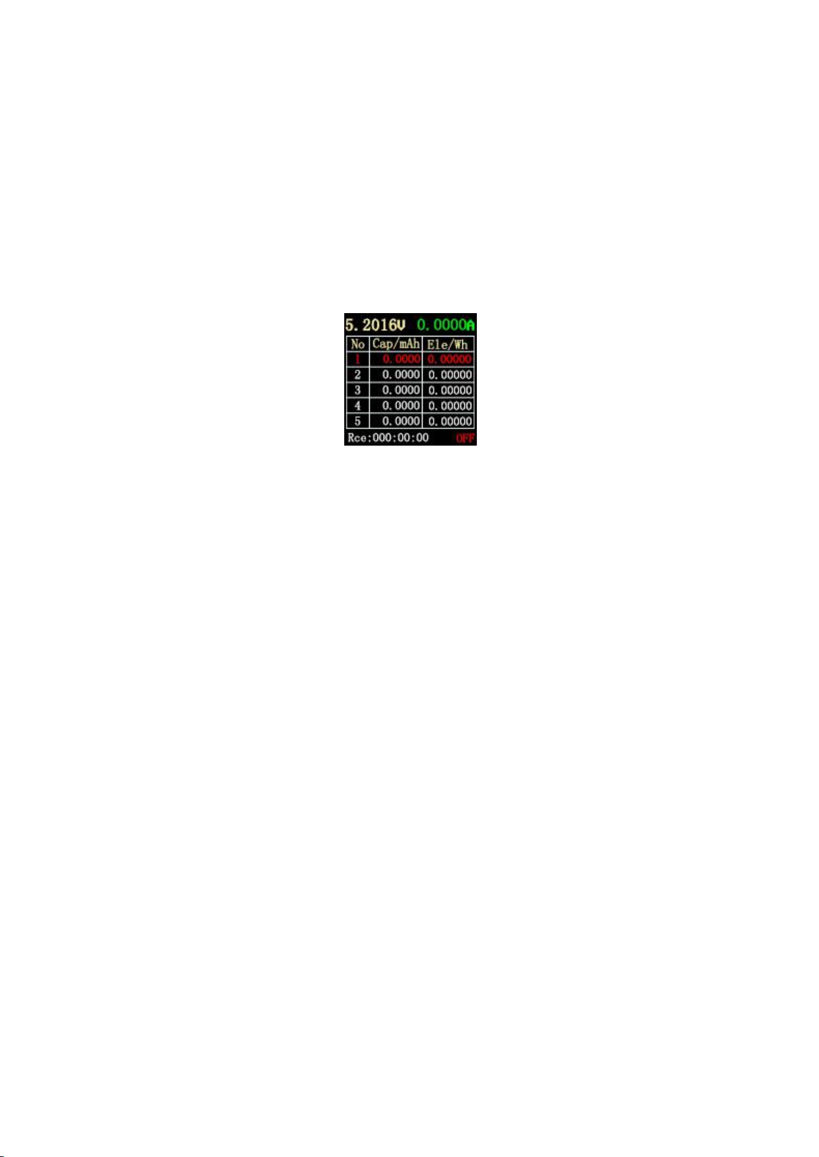
2、 Capacity / power consumption observation page (see Figure 3)
Figure 3
description
FNB38 supports 5 sets of capacity / power consumption records, and offline voltage and
current curve records.

7
Run:XXX:XX:XX Represents the tester's startup time, without saving, restarts the timer after
restart.
Rec:XXX:XX:XX It indicates the valid time of the tester's recording capacity / power
consumption. It is saved offline and will not be lost after power failure.
Time It shows the voltage and current offline curve recording time. This time can be set by
Cap / Ele Limit, and Rec:XXX:XX:XXRecord validity time for association or disassociation:
When Cap / Ele Limit is ON, the effective time of recording is limited by the time of offline curve recording.
For example, Time is set to 1h. After recording for 1h, offline curve recording is completed, and the capacity /
power consumption is no longer recorded. It is OFF. After the offline curve recording is completed, the capacity /
power consumption continues to be recorded. Cap / Ele Limit is OFF by default and can be set by the user.
Thres Indicates the recording current threshold.When the Auto Rec Switch is ON, Auto is
displayed. This value is meaningful, that is, when the current is greater than Thres, the capacity /
power consumption / offline curve is automatically recorded; if the current is less than Thres, no
recording is made.
When Auto Rec Switch is OFF, Manual is displayed, and the Thres value is meaningless.
Recording on / off is determined by the OK key. After recording is turned on, all records are
recorded regardless of the current.
Memor Indicates the remaining recording capacity of the offline curve. When it is 0%, the
recording is completed.
Grp:1/5 Indicates the record group.
ON/OFF Indicates the current recording status on / off.
Instructions
(1) << key
Short press: page turning;
(2) Long press: switch to capacity / power consumption list (see Figure 4) (see the following
description).
(3) >> key
Short press: page turning;
(4) Long press: switch record group.
8
(5) OK key
Short press: When set to manual recording, recording can be paused / started, and it is invalid
when set to automatic recording;
Long press: Clear the current group record data, including capacity, power consumption, and
record valid time.
3.Capacity / power consumption list (see Figure 4)
Figure 4
description
To facilitate the comparative analysis of multiple sets of capacity / power consumption data,
you can switch to the capacity / power consumption list (Figure 4).
Instructions
(1) << key
(2) Long press: Switch to the capacity / power consumption observation page (see Figure 3).
(3) >> key
Short press: switch observation group.
(4) OK key
Short press: When set to manual recording, recording can be paused / started, and it is invalid
when set to automatic recording;
Long press: Clear the current group record data, including capacity, power consumption, and record
valid time.
Method for clearing recorded data:(note)
(1) Press the OK button on the pages of Figure 3 and Figure 4 to clear the
capacity, power consumption, and recording time of each group.
9
(2) Offline record curve page (as shown in Figure 8), click OK, pop-up clear
confirmation window, you can clear the offline record curve separately.
(3) Select Clear all Records in the settings to clear all records (5 sets
of capacity / power consumption / recording time and voltage and current offline
recording curves). (Enter the follow-up instructions of the setting method)
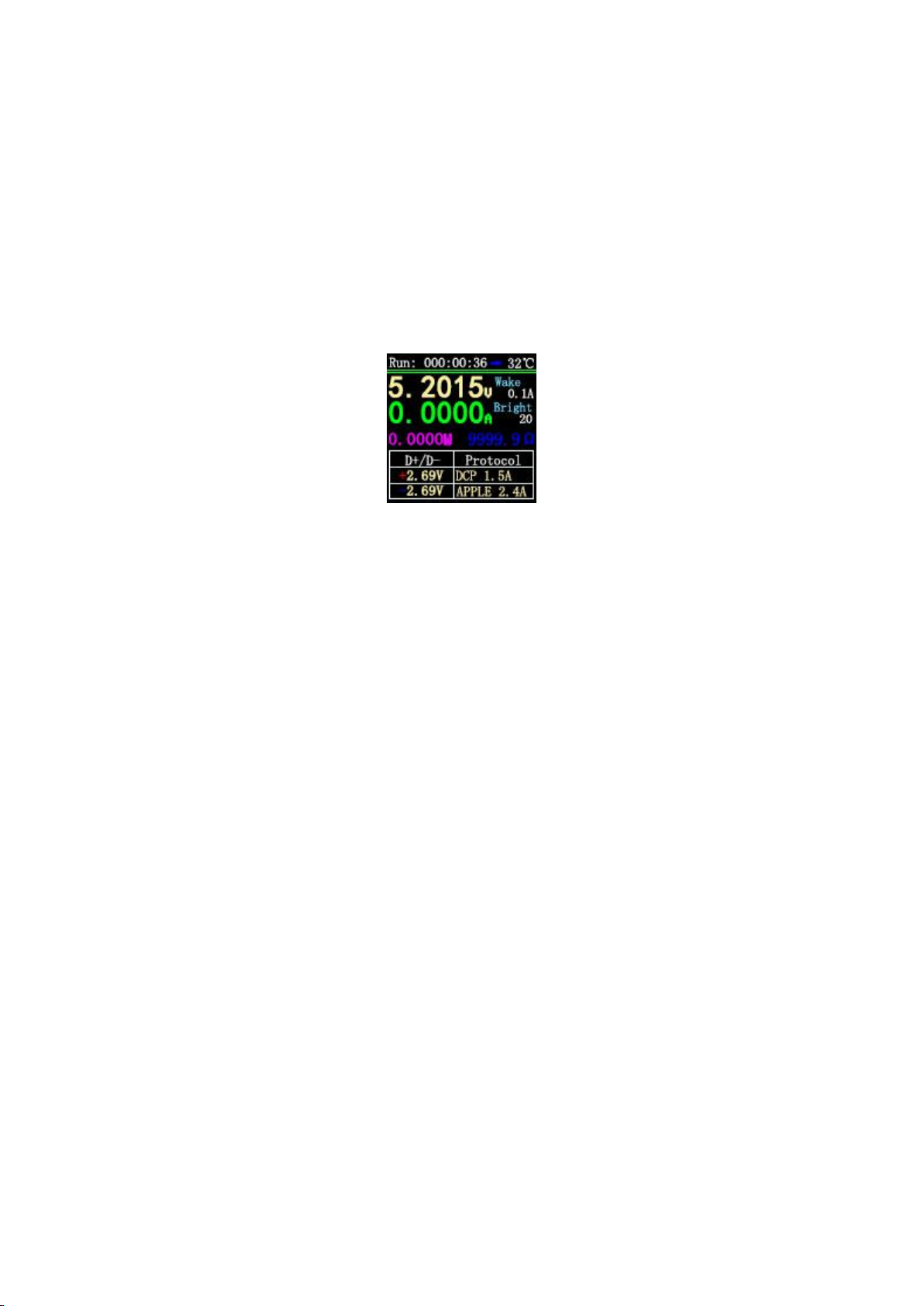
4.Fast charge identification page (see Figure 5)
Figure 5
description
This page is used to observe the current charging protocol, D + / D- voltage.
Wake Indicates automatic wake-up current, current change≥When Wake, exit from standby.
Bright Represents the current screen brightness.
Instructions
(1) << >> key
Short press: page turning;
(2) OK key
Short press: release D + / D-. When the fast charge trigger state (except the PD protocol), D + /
D- can be released to return to the non-trigger state.
5. Curve display page (as shown in Figures 6, 7, 8)
10
Figure 6Figure 7Figure 8
description
Figure 6 is the real-time curve of voltage and current.
Figure 7 shows the data D + and D- real-time curves.
Figure 8 shows the offline recording curve of voltage and current.
Instructions
(1) << >>key
Short press: page turning;
(2) Long press: Decrease / increase time base. (Only pages in Figures 6 and 7).
(3) OK key
Short press: screenshot curve; (Figures 6 and 7 are valid);
The curve clear window pops up; (Figure 8 is valid);
Long press: switch display curve.
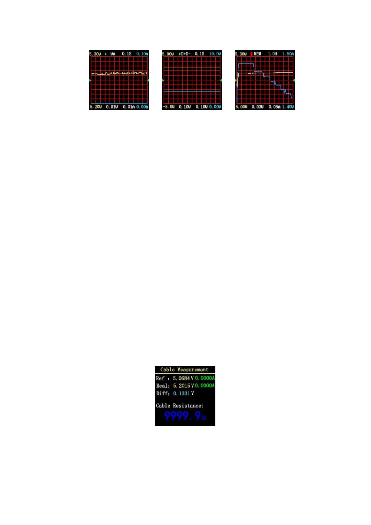
6.Cable measurement page (see Figure 9)
Figure 9
description
11
FNB38 uses the voltage drop method to measure the internal resistance of the cable. It needs to
be used with a constant current load.
Instructions
(1) << >>key
(2) Short press: page turning;
(3) OK key
Short press: Record the reference value. Long press: switch display curve.
Measurement steps
(1) Connection method: charger + FNB38 + constant current load (current adjusted to
about 1A), record the reference value.
(2) Connection method: charger + cable + FNB38 + constant current load (current adjusted
to about 1A), the system automatically calculates the cable internal resistance.
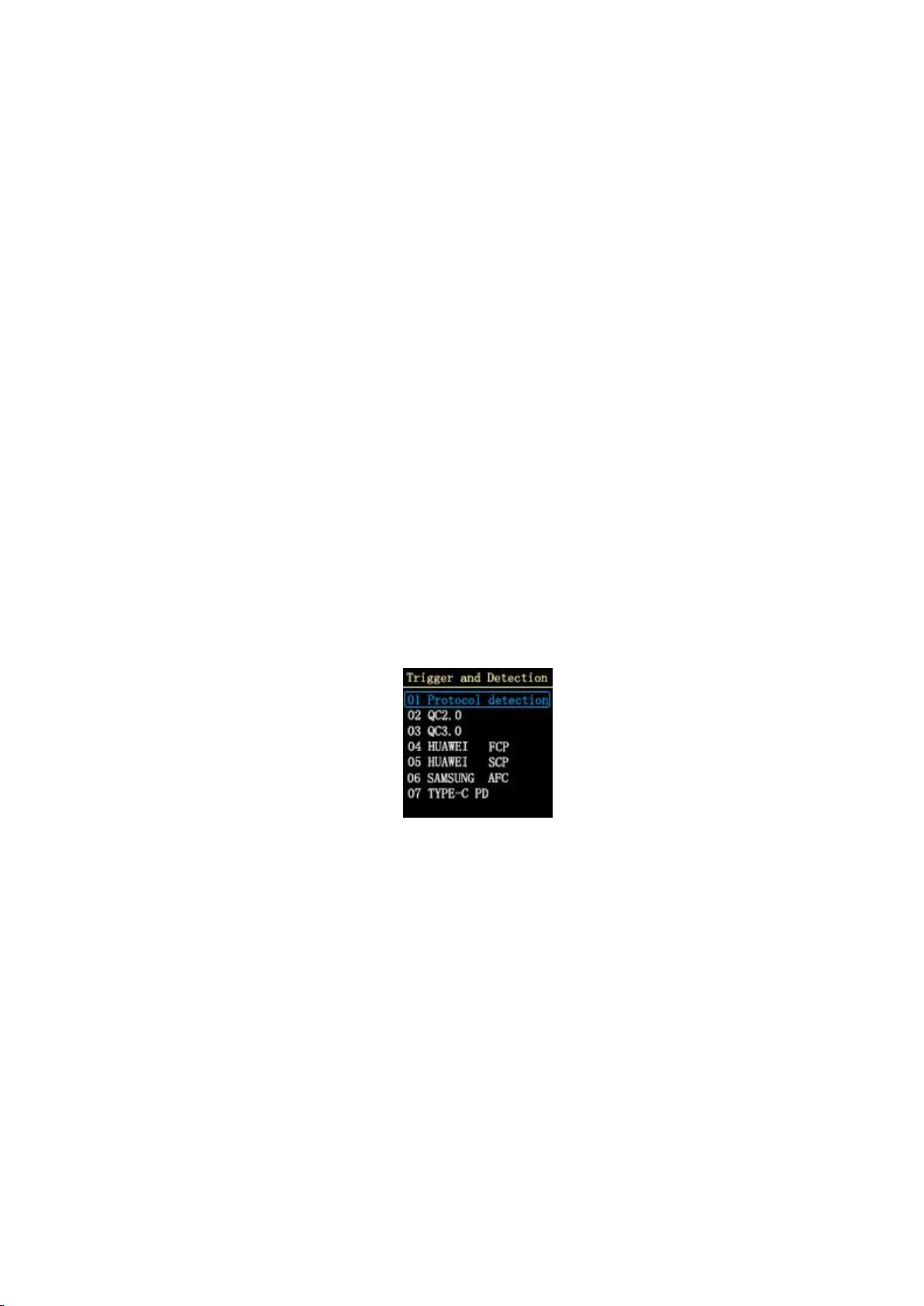
7.Fast charge detection and trigger page (see Figure 10)
Figure 10
description
Fast charge detection, fast charge trigger, short press OK to enter selection.
7.1 Fast charge protocol detection
After selecting Protocol detection protocol, short press OK to enter the state of automatic
detection of fast charging protocol.
After the test is completed, short press OK to exit the test interface.
Explanation:PD protocol detection, because some PD chargers will only send a complete PDO
after requesting the first voltage, and one-click detection will not make a voltage request, so the
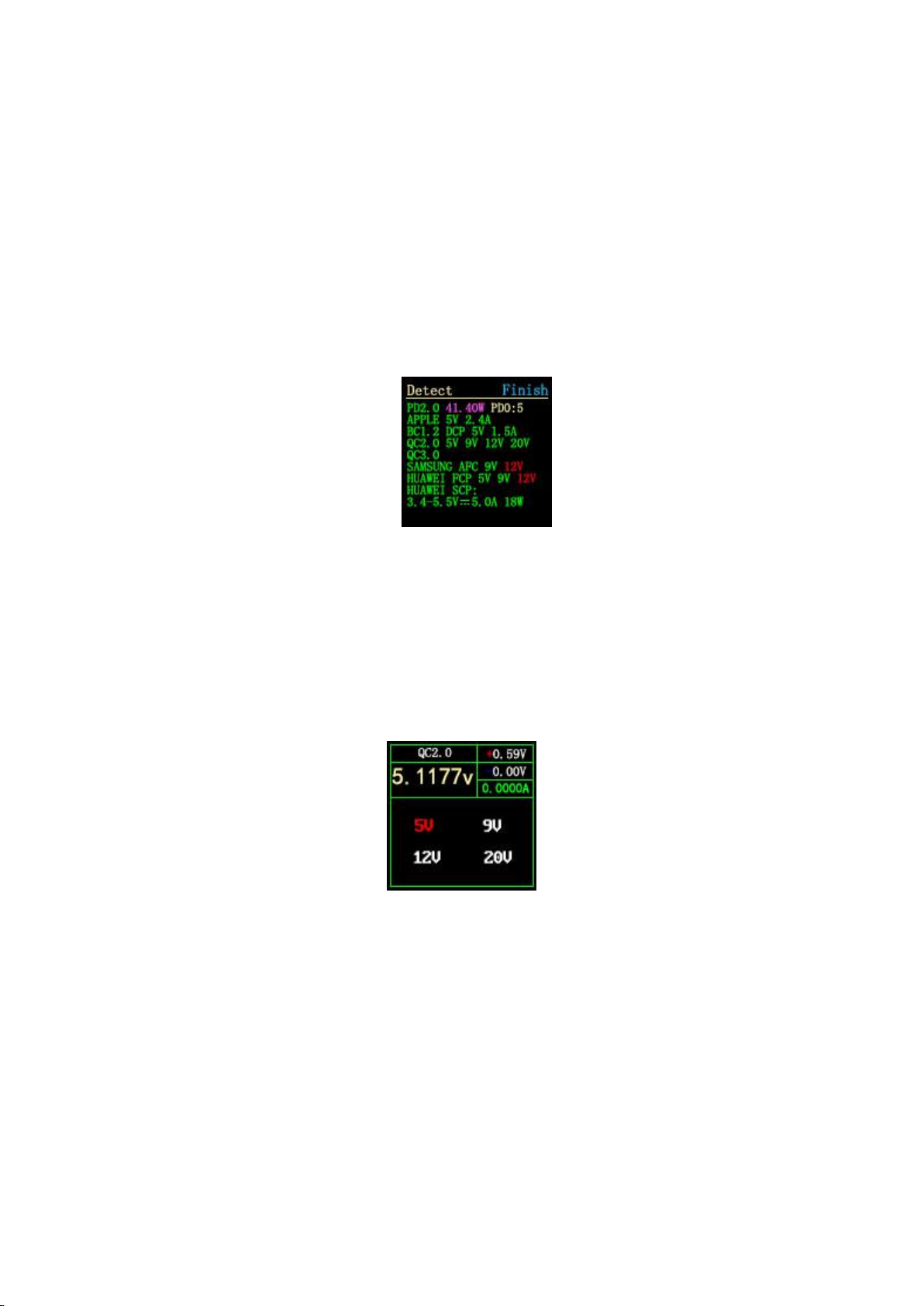
12
number of PDOs may be small. Complete PDO please trigger with PD Time shall prevail. If this
problem is solved, the firmware will be updated in the future.(For easier operation, DANGEROUS
will not be prompted after this version!!!)
Note: Do not connect any electrical appliances during the testing process, otherwise the high
voltage triggered during the testing process may burn the electrical appliances!
Note: Do not connect any electrical appliances during the testing process, otherwise the high
voltage triggered during the testing process may burn the electrical appliances!
Figure11 One-click detection page
7.2 QC2.0 trigger
Select QC2.0, press OK shortly to enter the QC2.0 trigger page (as shown in Figure 12),
Trigger Failure will display Trigger Failure!
Figure 12
Instructions
(1) << >>key
Short press: Switch the QC2.0 trigger voltage.
(2) OK key
Long press: Exit the current page. (Still triggering).
13
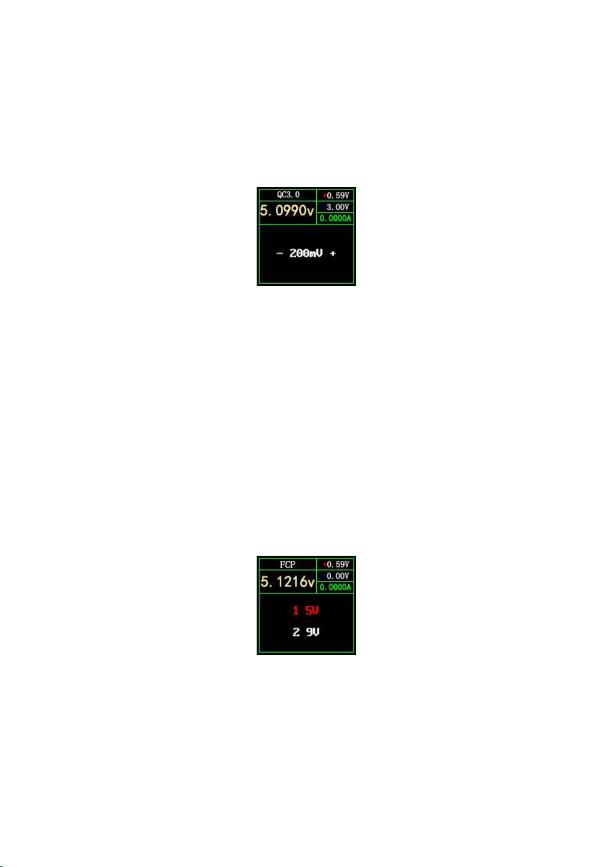
7.3 QC3.0 trigger
Select QC3.0, press OK shortly to enter the QC3.0 trigger page (as shown in Figure 13), Fail
Failure will display Trigger Failure!
Figure 13
Instructions
(1) << >>key
Short press: Decrease / increase QC3.0 trigger voltage.
(2) OK key
Long press: Exit the current page. (Still triggering).
7.4 Huawei FCP trigger
Select Huawei FCP and press OK to enter the Huawei FCP trigger page (see Figure 14). If the
entry fails, Trigger Failure! Will be displayed.
Figure 14
Instructions
(1) << >>key
Short press: Switch the FCP trigger voltage.

14
(2) OK key
Long press: Exit the current page. (Still triggering).
7.5 Huawei SCP trigger
Select Huawei SCP and press OK key to enter the Huawei SCP trigger page (as shown in
Figure 15). Trigger Failure will display Trigger Failure!
Figure 15
Instructions
(1) << >>key
Short press: Decrease / increase SCP trigger voltage.
(2) OK key
Long press: Exit the current page. (At the same time exit the SCP trigger state).
7.6 Samsung AFC trigger
Select Samsung AFC, press OK shortly to enter the Samsung AFC trigger page (as shown in
Figure 16), Fail Failure will display Trigger Failure!
Figure 16
Instructions
(1) << >>key
Short press: switch AFC trigger voltage. (When the charger does not support trigger voltage,

15
the voltage will return to 5V)
(2) OK key
Long press: Exit the current page. (Still triggering).
7.7 PD protocol trigger (requires connection to Type-C interface)
Select PD trigger, short press OK to enter the PD protocol trigger page (as shown
in Figure 17). When entering, it will detect whether PD detects the CC pull-up. If
not, return to the selection page. If there is a CC pull-up but no Caps are received,
the voltage option will not be displayed.
Figure 17
PD2.0 Instructions
(1) << >>key
Short press: Select PD trigger voltage.
(2) OK key
Long press: Exit the current page.
PD3.0 Instructions
(1) << >>key
Short press: Select trigger voltage. When the PPS is triggered, the voltage is lowered / raised.
OK button
(2) OK key
Short press: When the PPS trigger is selected, the step voltage unit is changed.
Long press: Exit the current page.
Note: PPS trigger requires continuous communication to maintain, so the charger will restart for a
period of time after exiting the interface.

16
7.8 PD protocol monitoring
On the hardware, you need to use two CC lines, the connection method is:
PD charger-CC line-FNB38-CC line-PD electrical appliances
In order to avoid losing data, you can use the HID interface to provide power.
When connecting, first connect the charger, FNB38 will automatically judge the
communication CC line and switch to the corresponding interface to monitor.
On the software, select PD monitor and short press OK button. If CC line is not
detected, it will return to the selection page; if CC line is detected, enter PD
monitor page 1 (see Figure 18).
Tip: PD monitoring only judges and switches to the corresponding CC line when
entering. If it has been entered successfully and then HID power supply is removed,
then the CC line connected to the charger is unplugged and inserted reversely. Because
the communication CC line is different, it cannot be monitored. Flip the CC line,
or exit the monitor and re-enter. When the monitoring function is not normal, you
can also go to page 2 to reset the monitoring information.
Because the CC line usually only has a single-sided CC, the two CC lines need
to be communicated with the CC line pair to monitor successfully.
Figure 18 Figure 19
PD monitoring Instructions
(1) << key
(2) Only valid on monitoring page 2 (Figure 19), short press: switch to view detailed
information of the message package; long press: reset monitoring information.

17
(3) >> key
Only valid on the monitoring page 2 (Figure 19), short press: switch to view the detailed
information of the message package; long press to hold to quickly browse down the information.
(4) OK key
Short press: You can switch between page 1 (Figure 18) and page 2 (Figure 19).
Long press: exit the current page.
7.9 PD E-Marker
This function can read the information of the CC line with the chip, use the HID
interface or 5V ordinary power supply (non-Type-C interface power supply), enter PD
E-Marker page 1 (Figure 20), this page shows some parsed CC lines Information, such
as supplier ID, maximum voltage, maximum current, length, etc. Short press >> button
to switch to page 2 (Figure 21), this page displays the unparsed original packet
information, users can parse the packet according to the manual to see if it matches
the data on page 1.
When Auto is green in the upper right corner, it means that the CC line is
automatically detected. At this time, no operation is required when plugging and
unplugging. The cable information will be automatically read. If you click OK to make
Auto gray, you will switch to manual mode. Information will not change. In manual
mode, you can click the << key to obtain the wire information.
Figure 20 Figure 21
18
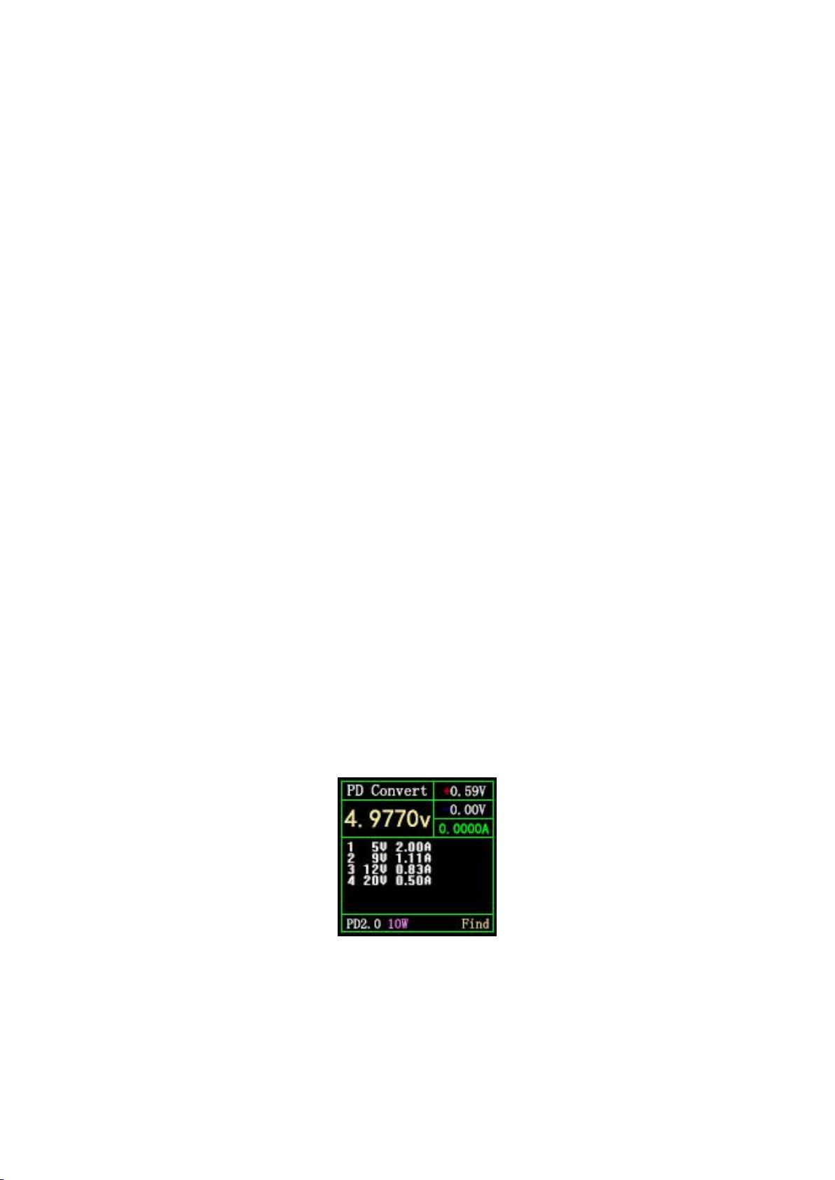
7.10 PD protocol conversion
This function can convert QC2.0 charging head to PD2.0 charging head for PD
electrical appliances. When entering the page, the system detects whether the
charging head supports QC2.0, if it does not support, it cannot enter.
This function automatically finds power-using equipment and supports 2-60W
broadcasting. You only need to change the power as needed. Be careful not to exceed
the power of the charger to avoid unnecessary damage.
Click the OK button to enter/confirm the power change. You can use the <</>> button
to change the power. After the power is changed, the broadcast will be resent. The
new power protocol is not triggered successfully. Please try to unplug and replug.
It is always 5V when no device is connected, to avoid high-voltage damage to mobile
phones that do not support high-voltage when plugged in.
QC2.0 only has a Class B charger that supports 20V triggering, so when PD
appliances request 20V voltage, the tester will detect whether the charger
successfully triggers QC2.0-20V. If it does not reach 20V, the tester will cancel
the 20V gear. And resend Caps broadcast.
In addition, some PD appliances will change the D+, D+ voltage during charging,
resulting in an abnormal QC2.0 trigger, and this type of charger cannot be charged
by this function.
Figure 22 PDChange page
Status description in the lower right corner:
Find:Looking for PD electrical appliances;
19
Send:Send Caps broadcast;
Wait:Waiting for voltage request;
Ready:The agreement is complete.
8.System information and setting page (see Figure 18)
Figure 18
description
Press and hold << to power on, FNB38 enters the system information and settings page.
VX.X Indicates the current firmware version.
SN:XXXXXX Indicates the unique serial number of the device.
Run:XXXXXX Represents the number of device runs.
Instructions
(1) << >>key
Short press: switch setting items.
(2) OK key
Short press: The setting window pops up.
Long press: Exit the setting page, and the device starts from the LOGO page.
Setting item description
The screen displays brightness settings, ranging from 1-20 levels.
OK key: short press: switch green dot position. Where is the green dot,
which corresponds to which operational block.
Long press: Effective when the green dots are NO / YES.
20
<< >> key: short press: when the green dot is at the maximum grid
(20Level, not explained later), change the parameter.
Standby screen display brightness setting, the range is 0-20 level,
when it is 0, the backlight is turned off.
OK key: short press: switch green dot position. Where is the green dot,
which corresponds to which operational block.
Long press: Effective when the green dots are NO / YES.
<< >> key: short press: when the green dot is on the largest grid,
change the parameter.
Standby time, ranging from 0-30 minutes. Does not stand by when
OFF.
OK key: short press: switch green dot position. Where is the green dot,
which corresponds to which operational block.
Long press: Effective when the green dots are NO / YES.
<< >> key: short press: when the green dot is on the largest grid,
change the parameter.
Automatic recording switch:
ON: recording when the current exceeds the threshold;
OFF: The current threshold is invalid, and recording is started and
stopped by pressing the button.
OK key: short press: switch green dot position. Where is the green
dot, which corresponds to which operational block.
Long press: Effective when the green dots are NO / YES.
<< >> key: short press: when the green dot is on the largest grid,
change the parameter.
Current threshold: effective when the automatic recording switch is
ON, current ≥this value, recording voltage and current equivalent.
OK key: short press: switch green dot position. Where is the green
Table of contents
Other Fnirsi Test Equipment manuals

Fnirsi
Fnirsi FNC88 User manual

Fnirsi
Fnirsi FNB48P User manual

Fnirsi
Fnirsi FNIRSI-1C15 User manual

Fnirsi
Fnirsi FNB48 User manual

Fnirsi
Fnirsi 1013D Instruction sheet

Fnirsi
Fnirsi DSO152 User manual

Fnirsi
Fnirsi DPOX180H User manual

Fnirsi
Fnirsi SG-003A User manual

Fnirsi
Fnirsi DPOX180H User manual

Fnirsi
Fnirsi FNB48P User manual


