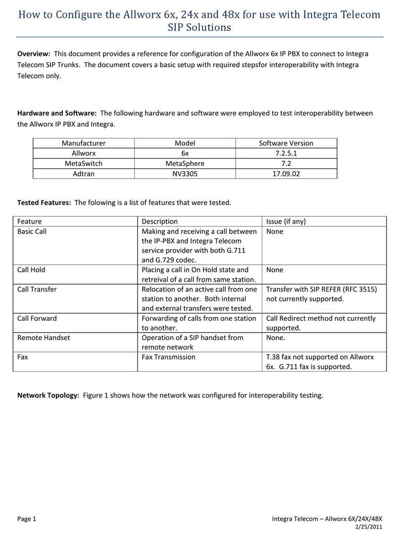
Allworx Connect Series User manual

Allworx® ConnectTM Server Family
Installation Guide
Version F Updated June 21, 2018


Allworx® ConnectTM Server Family
Installation Guide

Allworx® Connect™ Server Family Installation Guide
Page ii 866.ALLWORX * +1 585 421 3850
www.allworx.com
Version: F Revised: June 21, 2018
Copyright
Documentation
©2017 Allworx Corp, a Windstream company. All rights reserved. No part of this publication may be
reproduced, stored in a retrieval system, or transmitted, in any form or by any means, electronic,
mechanical, photocopy, recording, or otherwise without the prior written permission of Allworx Corp.
Software
Software in this product is Copyright 2017 Allworx Corp, a Windstream company, or its vendors. All
rights are reserved. The software is protected by United States of America copyright laws and
international treaty provisions applicable worldwide. Under such laws, the licensee is entitled to use
the copy of the software incorporated with the instrument as intended in the operation of the product
in which it is embedded. The software may not be copied, decompiled, reverse-engineered,
disassembled, or otherwise reduced to human-perceivable form. This is not the sale of the software or
any copy of the software; all right, title, ownership of the software remains with Allworx or its vendors.
Warranty
This warranty shall not apply to any products to the extent the defect or non-conformance is due to (A)
accident, alteration, abuse, misuse, or repair not performed by Allworx, (B) storage other than
specified, (C) failure to comply with applicable environmental requirements for the products.
Environmental Conditions
Allworx servers and phones:
Operating:
Temperature
Relative Humidity
+5° to 40° C / +41° to +104° F
5 to 90% (non-condensing)
Storage:
Low Temperature Point
High Temperature Point
High Relative Humidity Point
-40° C / +40° and any convenient humidity
+66° C / +150° 15% RH
+32° C / +90° 90% RH

Allworx® Connect™ Server Family Installation Guide
866.ALLWORX * +1 585 421 3850 Page iii
www.allworx.com
Version: F Revised: June 21, 2018
Trademarks
The following trademarks are owned by Allworx:
Revision History
Allworx® Verge™ IP phone series
Allworx® 92xx™ IP phone series
Allworx® Verge™ 9304
Allworx® Verge™ 9308
Allworx® Verge™ 9312
Allworx® Verge™ 9318Ex
Allworx® Reach™
Allworx® Reach Link™
Allworx® Extend™
Allworx® Interact™
Allworx® Interact™ Professional
Allworx® Interact Sync™
Allworx® View™
Allworx® View™ ACD
Allworx® OfficeSafe™
Allworx® Migrate™
Allworx® Connect™ servers
Allworx® Connect™ 731 server
Allworx® Connect™ 536/530 server
Allworx® Connect™ 536 server
Allworx® Connect™ 530 server
Allworx® Connect™ 324/320 server
Allworx® Connect™ 324 server
Allworx® Connect™ 320 server
Revision Date Description
A 03-JAN-2015 New Release
B 01-SEP-2015 Clarified mounting instructions
C 02-MAR-2017 Added Replaceable Battery Caution and translations
D 06-JUL-2017 Updated the Setup > Configure the Connect Server section.
Added Appendix A Restore Factory Defaults
E 17-MAY-2018 Added Accessories > Line In/Out specifications.
F 21-JUN-2018 Updated Introduction > Important Safety Instructions

Allworx® Connect™ Server Family Installation Guide
Page iv 866.ALLWORX * +1 585 421 3850
www.allworx.com
Version: F Revised: June 21, 2018

Allworx® Connect™ Server Family Installation Guide
866.ALLWORX * +1 585 421 3850 Page v
www.allworx.com
Version: F Revised: June 21, 2018
Contents
1 - Introduction ............................................................................................................. 1
1.1 - Who Should Read this Guide ..................................................................................................................... 1
1.2 - Guide Purpose ................................................................................................................................................. 1
1.3 - Guide Organization ........................................................................................................................................ 1
1.4 - Equipment Requirements ............................................................................................................................ 2
1.5 - Allworx System Software Compatibility ................................................................................................. 3
2 - Overview ..................................................................................................................5
2.1 - Packing List ....................................................................................................................................................... 5
2.2 - Front Chassis Views ........................................................................................................................................ 5
2.2.1 - Connect 731 Server ............................................................................................................................. 5
2.2.2 - Connect 536 Server ............................................................................................................................. 6
2.2.3 - Connect 530 Server ............................................................................................................................. 6
2.2.4 - Connect 324 Server ............................................................................................................................. 6
2.2.5 - Connect 320 Server ............................................................................................................................. 7
2.3 - Rear Chassis Views ......................................................................................................................................... 7
2.3.1 - Connect 731 Server ............................................................................................................................. 7
2.3.2 - Connect 500 Series Server ................................................................................................................ 7
2.3.3 - Connect 300 Series Server ................................................................................................................ 8
2.4 - Physical and Environmental Specifications ........................................................................................... 8
3 - Mount the Connect Server ..................................................................................... 9
3.1 - Tabletop or Shelf ............................................................................................................................................ 9
3.2 - Rack Mount .....................................................................................................................................................10
3.3 - Wall Mount .....................................................................................................................................................11
4 - Setup ...................................................................................................................... 13
4.1 - Install Checklist ..............................................................................................................................................13
4.2 - Electrical Connections .................................................................................................................................14
4.2.1 - Chassis Ground ...................................................................................................................................14
4.2.2 - Power Connection ..............................................................................................................................14
4.2.3 - Safe Mode Sequence ........................................................................................................................15
4.3 - Configure the Connect Server ................................................................................................................15
4.4 - Connect the Network Ports ......................................................................................................................19

Allworx® Connect™ Server Family Installation Guide
Page vi 866.ALLWORX * +1 585 421 3850
www.allworx.com
Version: F Revised: June 21, 2018
4.5 - Install Analog Telephony Ports ...............................................................................................................20
4.6 - Install the T1 Line ..........................................................................................................................................20
5 - Accessories (Optional) .......................................................................................... 23
5.1 - Line In/Out ......................................................................................................................................................23
5.2.1 - Relays ......................................................................................................................................................24
5.2.2 - Line Out ..................................................................................................................................................24
5.3 - Serial Port .........................................................................................................................................................24
6 - Troubleshooting .................................................................................................... 25
7 - Regulatory Notices ............................................................................................... 27
7.1 - FCC Part 68 ......................................................................................................................................................27
7.2 - Industry Canada ............................................................................................................................................27
7.3 - Radio and Television Interference ..........................................................................................................28

Allworx® Connect™ Server Family Installation Guide
866.ALLWORX * +1 585 421 3850 Page 1
www.allworx.com
Version: F Revised: June 21, 2018
Chapter 1 Introduction
The Allworx ® ConnectTM Server Family Installation Guide instructs Allworx administrators on the
setup and installation of the Connect server:
• unpacking the Connect server and accessories.
• mounting the Connect server:
• on a tabletop or shelf.
• in a rack.
• on a wall.
• performing electrical connections.
• configuring the Connect server.
• connecting the network ports.
• installing telephones.
• installing T1 (Connect server model 731 only).
• connecting accessories.
1.1 Who Should Read this Guide
This guide is for Allworx administrators that:
• install and maintain Allworx servers.
• understand computer networking and basic telephony.
• completed the Allworx Partner technical training.
1.2 Guide Purpose
The purpose this guide is to advise Allworx administrators on the set up, configuration, and installation
of a Connect server.
1.3 Guide Organization
This guide describes:
• requirements necessary to perform the operations described within the document.
• steps necessary to setup and install the Connect server.

Allworx® Connect™ Server Family Installation Guide
Page 2 866.ALLWORX * +1 585 421 3850
www.allworx.com
Version: F Revised: June 21, 2018
1.4 Equipment Requirements
The table below is a complete list of equipment and requirements necessary to perform all operations
identified in this Installation Guide.
Equipment Requirements
PC • Running OS (with latest service pack)
• Windows 7 32-bit SP1
• Windows 7 64-bit SP1
• Windows 8 32-bit
• Windows 8 64-bit
• Windows 8.1 32-bit
• Windows 8.1 64-bit
• Windows 10 32-bit
• Windows 10 64-bit
• RAM minimum: 2 GB
• Monitor resolution: 1024 x 768 (XGA)
• Internet connection
Allworx server • Server Software 8.0
• Administration permissions and passwords for each Allworx server.
• IP Address or DNS name of each Allworx server.
Allworx Portal • Login permissions and password
Supported Web Browsers • Microsoft Internet Explorer 11 (latest release with auto upgrade enabled)
• Microsoft Edge
• Google Chrome (Latest Release)
• Mozilla Firefox (Latest Release)
Allworx Server Administrator’s
Guide
The guide that describes the features and functionality of the Allworx System Software. This guide
is available at: https://allworxportal.com/.

Allworx® Connect™ Server Family Installation Guide
866.ALLWORX * +1 585 421 3850 Page 3
www.allworx.com
Version: F Revised: June 21, 2018
1.5 Allworx System Software Compatibility
Connect Server Model
320 324 530 536 731
Allworx System Software
System Software 8.0 XXXXX
Hardware Support
Enhanced Diagnostic Port XXXXX
Network Ports 22333
Supported Web Browser
Microsoft Internet Explorer 11 XXXXX
Google Chrome (latest version) XXXXX
Microsoft Edge XXXXX
Mozilla Firefox (latest version) XXXXX
Allworx System Software 8.0 Support
Activation Required XXXXX
Reach Link* XXXXX
Secure Web Page Access XXXXX
Enhanced Codec Support XXXXX
SIP-Video Pass-Through *** XXXXX
Allworx Server Features
FXO Ports 04062
FXS Ports 22222
T1 Ports** 00001
Base Users 12 12 30 30 30
Maximum Users* 20 20 50 50 180
Maximum Handsets 40 40 100 100 360
Maximum External Calls 12 12 30 30 60
Conference Bridges* 11114
Maximum Total Bridge Users 888830
Maximum Calls in All Queues* 12 12 30 30 60
Maximum Calls per Queue* 12 12 30 30 60
Maximum Number of Queues* 10 10 10 10 10
Automatic Call Distribution* No No Yes Yes Yes
Auto Attendant Ports 448816
Multi-Site Controller* Yes Yes Yes Yes Yes

Allworx® Connect™ Server Family Installation Guide
Page 4 866.ALLWORX * +1 585 421 3850
www.allworx.com
Version: F Revised: June 21, 2018
1.6 Important Safety Instructions
When using your telephone equipment, basic safety instructions should always be followed to reduce
the risk of fire, electric shock and injury to persons, including the following:
• Do not use this product near water for example: near a bathtub, washbowl, kitchen sink or
laundry tub, in a wet basement, or near a swimming pool.
• Avoid using a telephone (other than a cordless type) during an electrical storm. There may be a
remote risk of electric show from lighting.
• Do not use the telephone to report a gas leak in the vicinity of the leak.
• Use only the power cord and batteries indicated in this manual. Do not dispose of batteries in a
fire they may explode. Check with local codes for possible special disposal instructions.
SAVE THESE INSTRUCTIONS.
Voicemail Ports 448815
* Requires an Allworx software feature key.
** Feature key not required on the Allworx 24x server.
*** A SIP endpoint that supports video can register with the Allworx server, and it supports negotiation of video calls with that device.
The Allworx server enables up to two video sessions and one audio session per call. The Allworx server supported codecs are: H263,
H264, and MP4V-ES.
Connect Server Model
320 324 530 536 731

Allworx® Connect™ Server Family Installation Guide
866.ALLWORX * +1 585 421 3850 Page 5
www.allworx.com
Version: F Revised: June 21, 2018
Chapter 2 Overview
This section describes the Connect server:
• packing contents,
• front and rear chassis views, and
• physical and environmental specifications.
2.1 Packing List
Open the box and carefully unpack it. Save all shipping and packaging materials. Verify all items
against the parts list shown in the table below. If any items are missing, contact the dealer or Allworx
Customer Support at 866-255-9679.
2.2 Front Chassis Views
The following views indicate the features available on the front of each Connect server.
2.2.1 Connect 731 Server
Connect Server Family
Parts List 300 Series 500 Series 731 Series
Allworx Connect Server XXX
Power Cord X
12 VDC Power Supply XX
4 Rubber Feet (for Table Mount) XXX
Rack and Wall Mount Hardware Kit XXX
Allworx Connect Server Quick Start Guide XXX
Power
Button
Activity
Light
Console Serial
Connector
USB
Connector
Gigabit
Ethernet
Ports
T1 Port
Line Input
Jack and
Output
Inside Extension
Phone Port
Outside Phone
Line Ports

Allworx® Connect™ Server Family Installation Guide
Page 6 866.ALLWORX * +1 585 421 3850
www.allworx.com
Version: F Revised: June 21, 2018
2.2.2 Connect 536 Server
2.2.3 Connect 530 Server
2.2.4 Connect 324 Server
Power
Button
Activity
Light
Console Serial
Connector
USB
Connector
Gigabit
Ethernet
Ports
Line Input
Jack and Output
Inside Extension
Phone Port
Outside Phone
Line Ports
Power
Button
Activity
Light
Console Serial
Connector
USB
Connector
Gigabit
Ethernet
Ports
Line Input
Jack and Output
Inside Extension
Phone Port
Power
Button
Activity
Light
Console Serial
Connector
USB
Connector
Gigabit
Ethernet
Ports
Line Input
Jack and Output
Inside Extension
Phone Port
Outside Phone
Line Ports

Allworx® Connect™ Server Family Installation Guide
866.ALLWORX * +1 585 421 3850 Page 7
www.allworx.com
Version: F Revised: June 21, 2018
2.2.5 Connect 320 Server
2.3 Rear Chassis Views
The following views indicate the features available on the rear of each Connect server. The Page and
Door contacts are:
2.3.1 Connect 731 Server
2.3.2 Connect 500 Series Server
NO Normally Open
COM Common
NC Normally Closed
Power
Button
Activity
Light
Console Serial
Connector
USB
Connector
Gigabit
Ethernet
Ports
Line Input
Jack and Output
Inside Extension
Phone Port
Rear Terminal Connector Power Cord Connector
Protective Earthing Terminal
Rear Terminal Connector
Power Supply Connector
Protective Earthing Terminal

Allworx® Connect™ Server Family Installation Guide
Page 8 866.ALLWORX * +1 585 421 3850
www.allworx.com
Version: F Revised: June 21, 2018
2.3.3 Connect 300 Series Server
2.4 Physical and Environmental Specifications
The following table provides the physical and environmental specifications for each Connect server.
Connect Server Family
Specifications 300 Series 500 Series 731
Dimensions
(W x H x D)
11.875 x 1.75 x 5 inches
(32.2 x 4.4 x 12.7 cm)
13.32 x 1.75 x 5 inches
(33.8 x 4.4 x 12.7 cm)
17.125 x 1.75 x 5 inches
(43.5 x 4.4 x 12.7 cm)
Weight
(base model)
2.5 lbs (1.1 kg) 3.1 lbs (1.4 kg) 4.3 lbs (2 kg)
Power 12 VDC 1.5A
from external supply
100-240 VAC 50/60 Hz 500 mA
12 VDC 1.5A
from external supply
100-240 VAC 50/60 Hz 500 mA
115/230 VAC
0.6/0.4A, 60/50Hz
Temperature 41° ~ 104° F
(5° ~ 40° C)
41° ~ 104° F
(5° ~ 40° C)
41° ~ 104° F
(5° ~ 40° C)
Humidity 15% ~ 90% RH
Non-condensing
15% ~ 90% RH
Non-condensing
15% ~ 90% RH
Non-condensing
Rear Terminal Connector
Power Supply Connector
Protective Earthing Terminal

Allworx® Connect™ Server Family Installation Guide
866.ALLWORX * +1 585 421 3850 Page 9
www.allworx.com
Version: F Revised: June 21, 2018
Chapter 3 Mount the Connect Server
Allworx administrators can mount the Connect server on a tabletop, in a rack, or on a wall.
When selecting a mounting site, consider the following requirements:
3.1 Tabletop or Shelf
The table below indicates a list of all equipment necessary place the Connect server on a tabletop or
shelf.
Elevated Operating Ambient Verify maximum ambient temperature does not exceed 40°C. Rack operating ambient temperature may
exceed room ambient temperature.
Reduced Air Flow Proper air flow required for safe operation of the equipment.
Mechanical Loading Avoid hazardous conditions due to uneven mechanical loading.
Circuit Overloading Properly rated supply circuit (see equipment nameplate for ratings). Overloading the circuits may have
an effect on over current protection and supply wiring.
Reliable Earthing Maintain reliable earthing of rack-mounted equipment, especially supply connections other than direct
connections to the branch circuit (e.g. power strips).
Température ambiante de
fonctionnement élevée
Vérifiez que la température ambiante maximale ne dépasse pas 40 °C. La température ambiante de
fonctionnement de la baie peut être supérieure à la température ambiante de la pièce.
Circulation d'air réduite Vérifiez la circulation d'air nécessaire au bon fonctionnement de l'équipement.
Chargement mécanique Évitez toute situation susceptible d’être dangereuse pouvant être créée par un chargement mécanique
déséquilibré.
Surcharge du circuit Utilisez un circuit d'alimentation nominale approprié (consultez la plaque signalétique de l'équipement
au sujet des valeurs nominales). La surcharge des circuits peut avoir un effet sur la protection contre les
surintensités et sur les câbles d'alimentation.
Mise à la terre fiable Gardez une mise à la terre fiable des appareils installés dans une baie, notamment des connexions
d'alimentation autres que les connexions directes au circuit de dérivation (par exemple, les barres
d'alimentation).
Temperatura elevada del
ambiente operativo
Verifique que la temperatura ambiente no exceda los 40 °C. La temperatura ambiente operativa del
bastidor puede ser mayor que la temperatura ambiente de la habitación.
Flujo de aire reducido Verifique que exista el flujo de aire adecuado que se requiere para la operación segura del equipo.
Carga mecánica Evite las condiciones de riesgo debido a cargas mecánicas irregulares.
Sobrecarga de circuitos Utilice un circuito de abastecimiento del valor nominal apropiado (consulte los valores nominales en la
placa del equipo). El sobrecargar los circuitos puede tener un efecto en la protección contra sobrecargas
y en el cableado de suministro.
Sistema de puesta a tierra
confiable
Mantenga un sistema confiable de puesta a tierra para el equipo montado en el bastidor, especialmente
para las conexiones de suministro distintas de las conexiones directas al circuito (p. ej., barras de
contactos).
Equipment Qty
Rubber feet 4

Allworx® Connect™ Server Family Installation Guide
Page 10 866.ALLWORX * +1 585 421 3850
www.allworx.com
Version: F Revised: June 21, 2018
To install the Connect server on a tabletop or shelf:
1. Remove the four rubber feet from the packaging and turn the chassis over.
2. Remove the paper backing from one rubber foot and place it at a corner on the bottom of the
chassis.
3. Repeat for the remaining three rubber feet in the remaining three corners of the chassis.
3.2 Rack Mount
The table below indicates a list of all equipment and requirements necessary to rack mount the
Connect server.
To mount the Connect server:
1. Verify the clearance around the Connect server front and rear panels for the power, network,
and telephony connections.
2. Align a rack ear on the side of the Connect server so that:
• the four holes of the rack ear align with the four holes on the side of the Connect server.
• the perpendicular side of the rack ear faces outward from the front of the Connect server
to mount into the rack.
3. Secure to the Connect server chassis using four 6-32 flat head screws. Repeat for the opposite
side of the Connect server.
4. Follow the “Power Connection” on page 14 instructions.
5. Install the Connect server into the rack using appropriate hardware.
Equipment Qty Requirements
Rack 11U high rack mount standard 19” rack
Rack Mount Kit 1Includes:
• Two rack ears
• Eight 6-32 flat head screws

Allworx® Connect™ Server Family Installation Guide
866.ALLWORX * +1 585 421 3850 Page 11
www.allworx.com
Version: F Revised: June 21, 2018
3.3 Wall Mount
The table below indicates a list of all equipment and requirements necessary to wall mount the
Connect server.
Verify the correct orientation prior to mounting the Connect server to the wall.
To mount the Connect server to a wall:
1. Verify the clearance around the Connect server front and rear panels to accommodate the
power, network, and telephony connections.
Caution: Securely mount the Connect server to the wall to avoid equipment damage or personal injury.
MISE EN GARDE : Installez solidement le serveur Connect au mur, de façon à éviter dommages matériels et blessures.
PRECAUCIÓN: Monte el servidor Connect de manera segura en la pared para evitar daños al equipo o lesiones personales.
Note: For Connect 731 Wall Mount only: Discard the power cord and only use a UL listed power cord of type SJ or SO or
better.
Note: Mount the Connect server with the front facing left or right, not up or down
Equipment Qty Requirements
Rack 11U high rack mount standard 19” rack
Rack Mount Kit 1Includes:
• Two rack ears
• Eight 6-32 flat head screws
Required
wall mount
orientation

Allworx® Connect™ Server Family Installation Guide
Page 12 866.ALLWORX * +1 585 421 3850
www.allworx.com
Version: F Revised: June 21, 2018
2. Align a rack ear on the side of the Connect server so that:
• the four holes of the rack ear align with the four holes on the side of the Connect server.
• the perpendicular side of the rack ear aligns with the bottom of the Connect server.
3. Align the four holes on the rack ear with the four holes on the side of the Connect server and
secure to the Connect server chassis using the 6-32 flat head screws.
4. Repeat for the opposite side of the Connect server.
5. Use the upper and lower end of the Connect server mounting rack ears to mark the anchor
positions on the wall. Install self-drilling drywall anchors rated for at least 20 lbs with #6 or #8
screws per the anchor manufacturer’s recommendation.
6. Install the mounting screws through the rack ear holes and into the anchors. Tighten the screws
to secure the Connect server firmly against the wall.
This manual suits for next models
5
Table of contents
Other Allworx Server manuals

Allworx
Allworx 6x User manual

Allworx
Allworx 6x User manual

Allworx
Allworx 6x User manual

Allworx
Allworx Allworx 10x User manual

Allworx
Allworx Allworx 10x Quick reference guide

Allworx
Allworx Allworx 10x Installation instructions

Allworx
Allworx Allworx 10x User manual

Allworx
Allworx Allworx 10x User manual