Almex MVP User manual

MVP3 INSTRUCTION MANUAL Page 1
SHAW-ALMEX INDUSTRIES LIMITED 49908-006 NOV 97
Rev. DEC98, SEP99, MAY02
INSTRUCTION MANUAL
MVP
LIGHTWEIGHT BELT VULCANIZER
This manual was prepared to present the correct methods and procedures of operating and
maintaining your ALMEX VULCANIZER.
At the time of writing this manual, the instructions were up to date. However, some of the
information or appearance of the component parts may vary slightly from the vulcanizer
delivered to you.
Read this manual carefully before operating your vulcanizer.
SHAW-ALMEX INDUSTRIES LIMITED
P.O. Box 430
Parry Sound, Ontario, Canada P2A 2X4
Phone: 705-746-5884 or toll-free 800-461-4351
Fax: 705-746-9484
Web: www.almex.com

MVP3 INSTRUCTION MANUAL Page 2
SHAW-ALMEX INDUSTRIES LIMITED 49908-006 NOV 97
Rev. DEC98, SEP99, MAY02
Table of Contents
1. RECORD OF PURCHASE ...............................................................................................................3
2. DECLARATION OF CONFORMITY ................................................................................................4
3. SAFETY .............................................................................................................................................5
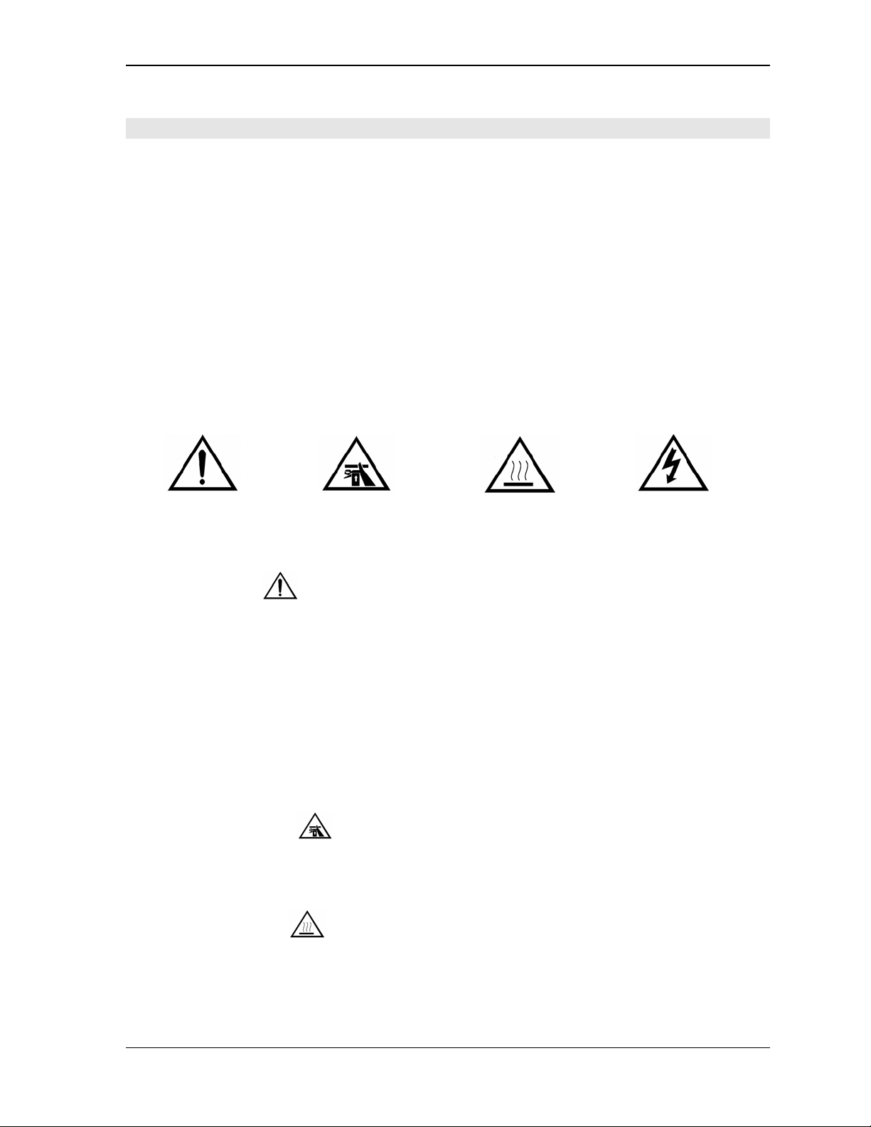
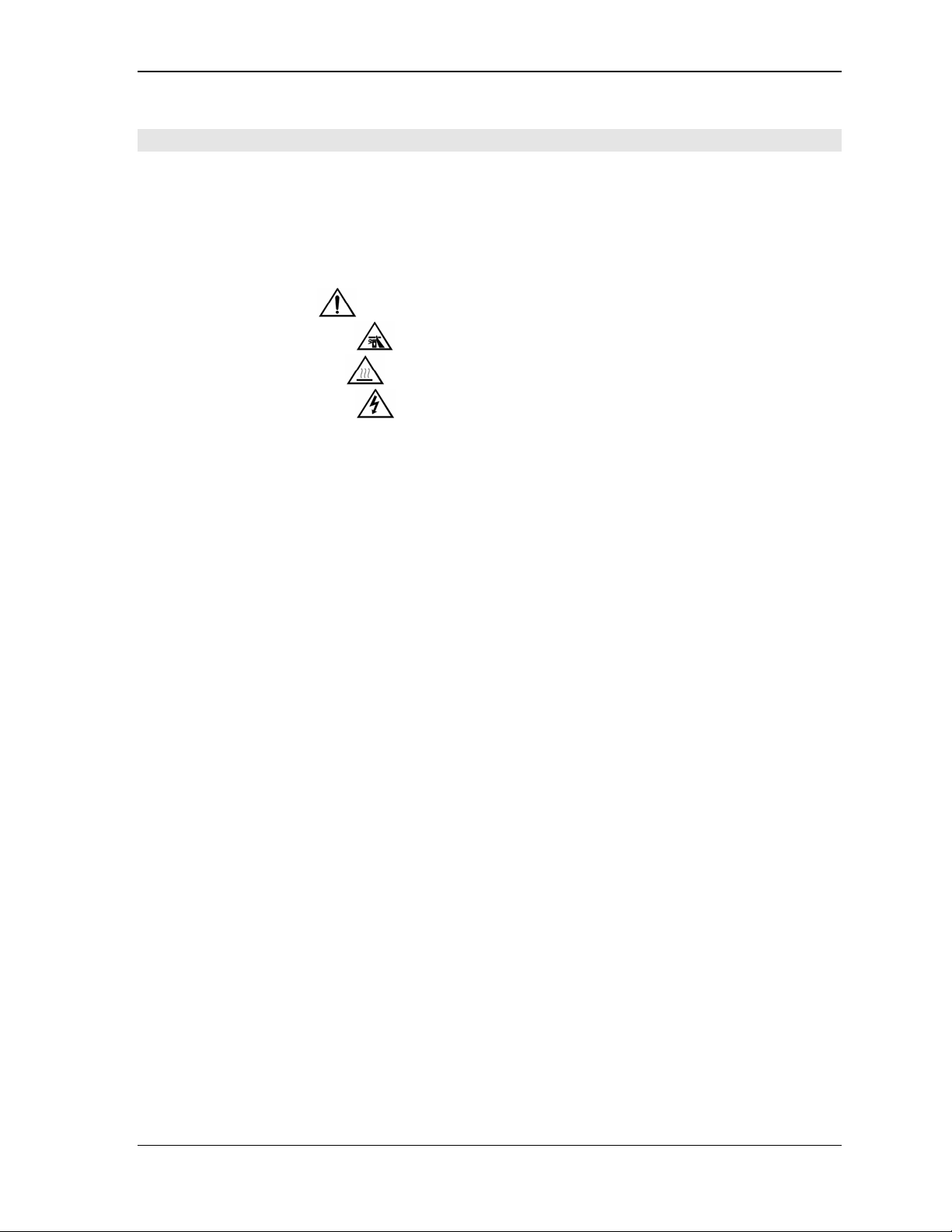
3.1. Definition of Pictograms .................................................................................................5
3.1.1. Safety Alert .......................................................................................................5
3.1.2. Crushing Hazard ...............................................................................................5
3.1.3. Burning Hazard .................................................................................................5
3.1.4. Electrical Hazard ...............................................................................................6
3.2. Limitation of use .............................................................................................................6
3.3. Hazardous Materials and Products ................................................................................6
3.4. Safe Handling .................................................................................................................6
4. ASSEMBLY .......................................................................................................................................7
4.1. Functional Diagram ........................................................................................................7
4.2. Unpacking.......................................................................................................................7
4.3. Vulcanizer Set-Up...........................................................................................................7
4.3.1. Basic Assembly...........................................................................................................8
4.3.2. Hinging Top Frame .....................................................................................................8
4.3.3. Short Circumference Belt............................................................................................8
5. OPERATION......................................................................................................................................9
5.1. Splice Set-Up..................................................................................................................9
5.2. Pressurizing with Air.......................................................................................................9
5.3. Heating the Vulcanizer ...................................................................................................9
5.4. Cooling the Vulcanizer .................................................................................................10
5.5. Depressurize ................................................................................................................10
6. MAINTENANCE ..............................................................................................................................10
6.1. Routine Maintenance ...................................................................................................10
6.2. Replacing the Pressure Bag.........................................................................................11
6.3. Replacing Heating Element..........................................................................................11
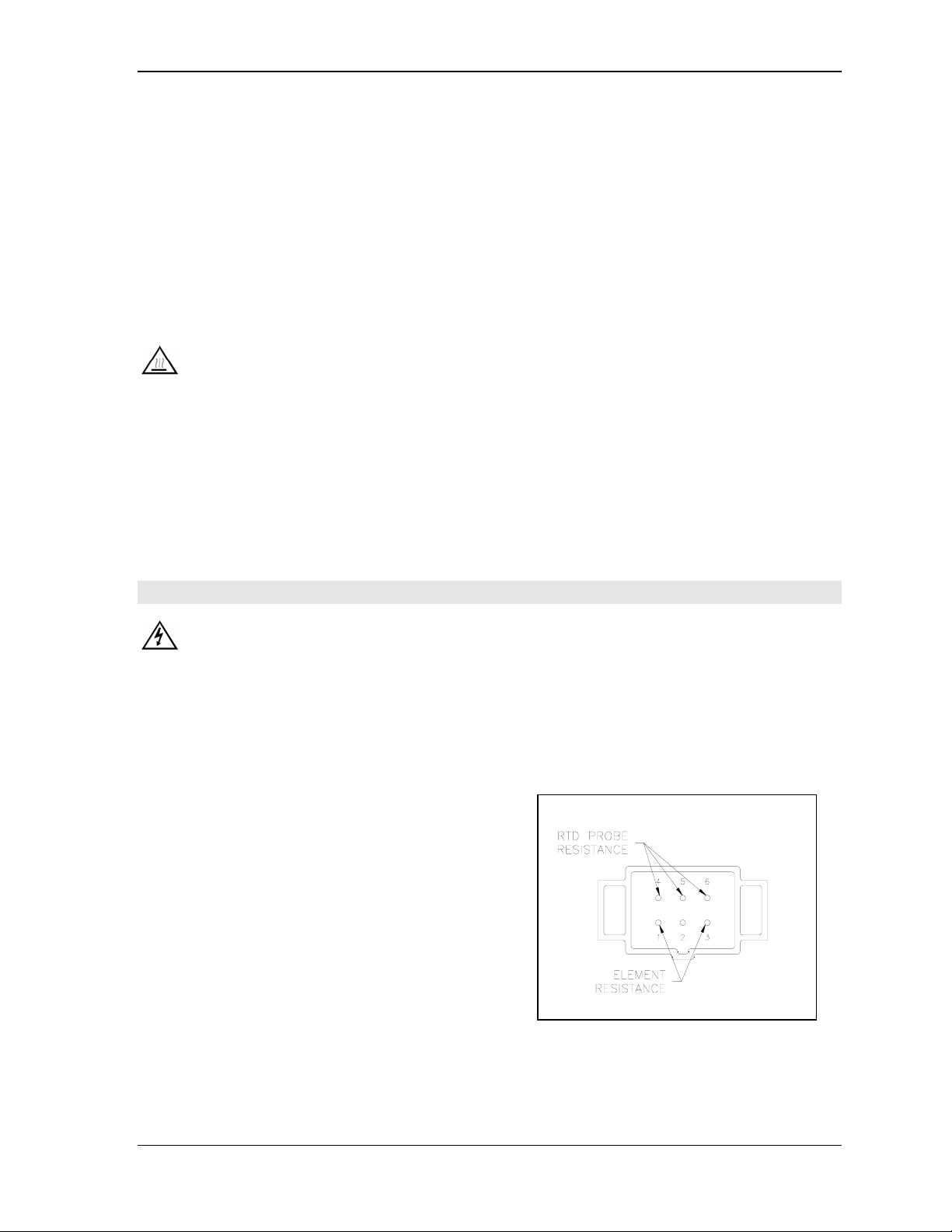
6.4. Replacing the Temperature Sensor (RTD Probe)........................................................11
7. TROUBLESHOOTING....................................................................................................................12
7.1. Vulcanizer Not Heating.................................................................................................12
7.2. Vulcanizer Over Heating ..............................................................................................12
7.3. No Pressure or Loss of Pressure .................................................................................13
8. SERVICE..........................................................................................................................................13
8.1. Emergency Service ......................................................................................................13
8.2. Return of Goods Authorization .....................................................................................13
8.3. Guarantee.....................................................................................................................13

MVP3 INSTRUCTION MANUAL Page 3
SHAW-ALMEX INDUSTRIES LIMITED 49908-006 NOV 97
Rev. DEC98, SEP99, MAY02
1. RECORD OF PURCHASE
JobNumber
DateofPurchase
ModelNumber
SerialNumber
Platen Size
Weight Total
Top Frame with Platen
PlatenOnly
Operating Pressure
Voltage
Phase
Cycle/Hertz
Amperage Per Platen
Total
Element Construction
Element Resistance: Coils Connected
Coils Open
Temperature Controller Model
Calibration Temperature
Ancillary Items
Optional Items Platen cover plates
Beltclamp
Quick connect cooling fittings
Cylinder lift
Retractable handle
SpareParts
Operating Instructions 49908-006
Supplements
Service Bulletins
Warranty Card
Drawings
Parts Diagrams MVP-F (frame), MVP-P (platen) MVP-AC (air control)

MVP3 INSTRUCTION MANUAL Page 4
SHAW-ALMEX INDUSTRIES LIMITED 49908-006 NOV 97
Rev. DEC98, SEP99, MAY02
2. DECLARATION OF CONFORMITY
We, Shaw-Almex Industries Limited,
of P.O. Box 430, Parry Sound, Ontario, Canada,
declare that the machinery:
Product: Vulcanizer
Model: MVP
Year of Certification: 1998
has been manufactured using the following transposed harmonized European Standards:
EN 60204-1 Safety
EN 50081-1 Emissions (EN55011)
EN 50082-1 Immunity (EN61000-4-2/3/4/5)
and is in conformity with the following Directives:
73/23/EEC Low Voltage Directive + amendment 93/68/EEC
89/336/EEC EMC Directive + amendment 92/31/EEC
89/392/EEC Machinery Directive
Signed in: Parry Sound, Ontario, Canada
on
Name: Lawrence B. Woolner, P.Eng.
Position:: Manager of Engineering

MVP3 INSTRUCTION MANUAL Page 5
SHAW-ALMEX INDUSTRIES LIMITED 49908-006 NOV 97
Rev. DEC98, SEP99, MAY02
3. SAFETY
Your vulcanizer has been designed to provide safe, efficient, trouble-free service for many years. Component
design and material selection have been carefully considered to ensure operator safety and our manufacturing
procedures provide a consistent, high-quality product.
The material that is presented in this operating manual has been compiled to provide direction for operating
personnel so that the maximum effectiveness of the vulcanizer can be achieved and so that there is a complete
understanding of correct operating procedures.
PLEASE READ CAREFULLY
The following safety precautions should be read carefully and understood thoroughly before you set-up or
operate your vulcanizer. Failure to follow these precautions may result in personal injury and/or equipment
damage. All operating personnel should be trained in the proper method of handling and operating the
vulcanizer.
The risks associated with operating the vulcanizer are identified throughout this manual with pictograms.
Safety Alert Crushing Hazard Burning Hazard Electrical Hazard
3.1. Definition of Pictograms
3.1.1. Safety Alert
1. Never operate the press while unattended.
2. The upper frame must be securely assembled into the lower frame before pressurizing vulcanizer. Do not
lean against or over top of the vulcanizer during operation. Since high stress levels are resident in the frame
and latch during operation, component failure can result in parts being projected upward or outward.
3. Do not connect the vulcanizer to a continuous pressure supply. In the event of component failure, it is
important for the pressure to drop to a safe level.
4. Do not tamper with the pressure relief valve. It is factory preset to prevent the vulcanizer from operating at
unsafe pressures.
5. Use hoisting provision provided on larger frames.
3.1.2. Crushing Hazard
1. Fingers must not be placed between platen surfaces when the vulcanizer is pressurized or injury will result.
2. There is a crushing hazard when assembling the press if the top frame is lowered onto the bottom frame.
3.1.3. Burning Hazard
1. The platen surfaces typically operate at or above 300°F (150°C). Touching these surfaces will result in a
burn.

MVP3 INSTRUCTION MANUAL Page 6
SHAW-ALMEX INDUSTRIES LIMITED 49908-006 NOV 97
Rev. DEC98, SEP99, MAY02
2. The cooling water may discharge from the platen initially as steam creating a burning hazard. Ensure the
cooling water discharge is not directed at any person or injury could result.
3. Improper use or component failure could result in the vulcanizer overheating. Always use an Almex
temperature controller when operating the vulcanizer and never leave the vulcanizer operating while
unattended.
3.1.4. Electrical Hazard
1. A qualified electrician should perform all maintenance of the electrical components of the vulcanizer.
2. All of the electrical components contain live circuits. Do not open or service any of the electrical
equipment without disconnecting the main power supply.
3. Incorrect voltage and phase may result in component damage and create a fire hazard.
4. Equipment power supplies must be properly grounded or a severe shocking hazard may result.
5. Avoid using equipment in wet surroundings or a severe shocking hazard may result.
6. If any cable or connectors are damaged, they must be replaced or a fire and shock hazard may result.
3.2. Limitation of use
This equipment has been designed to vulcanize conveyor belts. The process of vulcanizing is done by applying
a combination of heat and pressure on the product for a certain period of time. The MVP press operates within
a pressure range of 0-40 psi. There is a built in safety pressure control that must be used. A continuous pressure
supply must not be connected to the press. The platens can be operated at temperatures up to 450°F (230°C).
The press is to be connected to an ALMEX temperature control panel that is supplied complete with platen
electrical cables. The press must never be allowed to operate while unattended. Hoses have been provided to
connect a cooling supply to the press. Other use is not allowed without the written permission of Shaw-Almex.
3.3. Hazardous Materials and Products
The cooling water may discharge from the platen initially as steam creating a burning hazard. Ensure the
cooling water discharge is not directed at any person or injury could result.
Compressed air is generally used to pressurize the press. Never direct compressed air flow at a person. Never
connect the vulcanizer to a continuous air supply.
3.4. Safe Handling
Handling the machine does present some residual hazard. The weight of the components is marked on the
component. Handles are provided on the frames. For the bigger presses, hoisting equipment is needed to
position the top frame in place. Hoisting provision is on the frame.
Wear protective footwear when handling the press.
Connection of cables and hoses must be made in such a way that no tripping hazard is created.

MVP3 INSTRUCTION MANUAL Page 7
SHAW-ALMEX INDUSTRIES LIMITED 49908-006 NOV 97
Rev. DEC98, SEP99, MAY02
4. ASSEMBLY
4.1. Functional Diagram
There are two essential requirements for perfect splicing of conveyor belting; Uniform Pressure and a
controlled Uniform Temperature. Both of these requirements are satisfied in the ALMEX Vulcanizer.
Uniform Pressure:
Full platen size pressure ‘bag’ applies uniform pressure over the entire platen area.
Important
This unique platen requires support over its entire area or permanent distortion of the platen may occur. Fill
any unused portion of the platen area with scrap belting or shims the same thickness as the belting being cured.
Uniform Temperature:
The heating element is a silicone rubber ‘blanket’ which covers the total platen surface.
4.2. Unpacking
Carefully unpack vulcanizer from the crate and inspect for damage.
Any damages or shortages should be reported to the carrier and / or Shaw-Almex Industries Limited.
4.3. Vulcanizer Set-Up
The MVP vulcanizer can be used in several ways depending on the application. The presses are assembled at
the factory with both platen electrical connectors on one end and the air control on the other. The platens can be
turned end for end if desired so that both platen electrical connectors and the air control are on the same end.
The MVP is supplied with a separate top frame and bottom frame that makes it very easy to handle in most field
applications. In shop applications, it is often convenient to fasten the frames together and to hinge the top and
bottom frames. Hinging the top frame can be done easily on all models.
The platens on the MVP can be easily removed from the frame while the platen remains fully assembled. This
makes the platens very versatile as they can be used without the frame at lower temperatures to warm a belt and
they can be easily interchanged with a custom frame on special applications. Another advantage of having the

MVP3 INSTRUCTION MANUAL Page 8
SHAW-ALMEX INDUSTRIES LIMITED 49908-006 NOV 97
Rev. DEC98, SEP99, MAY02
platen separate from the frame is that short circumference belt can be wrapped around only the platen and
spliced. Splicing short circumference belt can be done easily on all models.
4.3.1. Basic Assembly
Safety: The vulcanizer should be assembled and operated on a flat, level and stable surface so there is no
danger of falling.
1. Position the top frame on the bottom frame using the legs for alignment. It is best to have the platen
electrical connectors on the same end.
2. Raise the pressure hoops onto the top frame. They will be safely in position when they clear the raised edge
of the frame end plate.
3. Connect the top and bottom platen electrical cables to the platen connectors.
4. Connect the top and bottom platen electrical cables to the temperature control panel and connect panel to
power supply. See temperature control manual.
5. Connect the top and bottom platen cooling supply and drain hoses.
4.3.2. Hinging Top Frame
The top frame can be made to hinge on all models by fastening the top frame to the hoop as follows. Typically
the end with the platen cables is the hinging end and the air control is on the opposite end. The procedure refers
to the hinging end.
1. Remove the plastic handle from the hoop on the end that will hinge. Keep the fasteners.
2. Remove the two standoffs from the top frame on the end that will hinge.
3. Remove the end plate with handle from the top frame on the end that will hinge.
4. From inside the top frame, fasten the top frame to the hoop using the fasteners from the plastic handle.
5. Replace the end plate with handle on the top frame.
The top frame will now hinge open easily.
4.3.3. Short Circumference Belt
The MVP vulcanizer is designed to facilitate the splicing of short circumference belt by allowing the belt to be
wrapped around the lower platen. Note that this feature cannot be used with the belt clamp. Call your ALMEX
distributor if a custom application is required.
1. Remove the four screws fastening the bottom platen to the bottom frame.
2. Lift the platen clear of the frame.
3. Slide the prepared belt(s) over the lower platen.
Tip: A pad should be placed between the platen tray and the belt or the platen assembly screws will mark the
belt.
4. Replace platen to frame. The lower frame standoffs ensure that the platen will be positioned properly on
the lower frame.
5. The four screws fastening the bottom platen to the bottom frame do not have to be installed for proper
operation.

MVP3 INSTRUCTION MANUAL Page 9
SHAW-ALMEX INDUSTRIES LIMITED 49908-006 NOV 97
Rev. DEC98, SEP99, MAY02
5. OPERATION
5.1. Splice Set-Up
The procedure below describes the operation of the vulcanizer basic assembly with no options. Separate
instructions are supplied with the options.
1. Lower hoops and lift top frame from the bottom frame.
Safety: A hoisting ring is installed on presses over 100 lb. (50 kg).
2. Prepare the splice as required.
3. Position splice on lower platen. It is good practice to use platen covers between the belt and the top and
bottom platens. It is also common practice to use a pad on the lower platen.
4. Position top frame on the bottom frame, aligning the top and bottom frame standoffs.
Safety: Crushing hazard
5. Raise the pressure hoops onto the top frame. They will be safely in position when they clear the raised edge
of the frame end plate.
Safety: Failure to engage the pressure hoop completely could result in over stroke damage to the
vulcanizer and injury when pressure is applied.
5.2. Pressurizing with Air
Safety: Do not lean against the vulcanizer when pressurizing. Component failure can result in
components being projected upward or outward. People must stay clear of the area when press is in operation.
Safety: The Air Release/Pressure Relief valve is preset to blow off at 50 p.s.i. Do not override this safety
device or injury could result.
1. Turn the safety relief valve toggle so it is at a right angle with the valve.
2. Apply air (using compressed air or a hand / foot pump) until the desired air pressure is reached as indicated
on the gauge. Make sure air is actually entering the pressure bag before commencing to heat the platens.
3. To de-pressurize the vulcanizer, turn the toggle on the pressure relief valve so it is in line with the body of
the valve.
5.3. Heating the Vulcanizer
Safety: Never heat the vulcanizer while unattended.
1. Adjust the set point value of the temperature controller. If not familiar with the temperature controller,
refer to the manual supplied with the temperature controller for instruction.
2. Turn the switches on the temperature controller to the ON (1) position.
Safety: The platens will get hot.
3. Heat to set point temperature and then time the cure according to the belt manufacturer’s specification.
Monitor the platen temperature with the stem thermometers as well as the controller display.
Tip: The use of different platen cover plates will affect the heat up time and may cause a difference between
the controller temperature reading and the actual temperature of the product. Cure temperatures and times
may have to be adjusted to compensate for this difference.
4. When the cure is finished, turn the switches on the temperature controller to the OFF (0) position.

MVP3 INSTRUCTION MANUAL Page 10
SHAW-ALMEX INDUSTRIES LIMITED 49908-006 NOV 97
Rev. DEC98, SEP99, MAY02
5.4. Cooling the Vulcanizer
1. When the cure time has been completed and the temperature controllers are switched to the OFF (0)
position, turn on the water supply to cool the upper and lower platens. Leave the power supply connected
to temperature controller so the platen temperature can be monitored.
2. When the platens have cooled to an acceptable temperature, the cooling water can be turned off. A typical
cool down temperature for a good splice result and safe handling of the belt without the risk of a burn is
150°F (65°C).
3. The water must be blown out with air before the platens are reheated. Water remaining in the cooling
channels will reduce platen temperature uniformity, increase the heat-up time and may cause the elements
to overheat. Furthermore, if water remains in the platens and the vulcanizer is stored at temperatures below
freezing the platens may be severely damaged.
Safety: The cooling water may discharge from the platen initially as steam creating a burning hazard.
Ensure the cooling water discharge is not directed at any person or injury could result.
Tip: The standard cooling hoses and fittings on the MVP vulcanizer are of the highest quality have been
selected for their durability and their ability to cool the platen s quickly with a minimal amount of water.
The passages in the hoses and fittings are small and may become restricted if there is any solid matter in
the cooling water, and this will effect the cooling rate. Always use clean water for cooling and clean the
fittings if the cooling time becomes excessive.
5.5. Depressurize
1. To depressurize the vulcanizer, turn the safety relief valve toggle so it is in line with the valve.
6. MAINTENANCE
Safety: All maintenance must be done with the vulcanizer disconnected from the power supply and no
pressure in the bag.
There are no special tools required to maintain this equipment.
6.1. Routine Maintenance
The following items should be checked after every thirty cures.
1. Visually inspect the frames, pressure hoops and hinge
pins for signs of cracking or deformation.
1. Check the continuity of the platen heating elements.
Refer to “Record of Purchase” for the resistance (ohms)
values. Use the figures from the “Ohms Reading Coils
Connected” column.
2. Check the continuity of the platen temperature sensor.
3. Check the platen pressure bag for damage due to
abrasion, cuts or any type of damage which might cause
a leak or breakdown while under pressure. It can be
checked quickly by removing the bag cover plates.
4. Check all cables for cuts, abrasion and wear and all
“strain relief” fittings between cable and plugs for a secure fit. If any cable, hose, fitting or pressure bag
shows signs of damage they should be repaired or replaced.
5. The platen cooling should be checked for leaks and/or blockages which will affect their performance.
Platen Electrical Connector

MVP3 INSTRUCTION MANUAL Page 11
SHAW-ALMEX INDUSTRIES LIMITED 49908-006 NOV 97
Rev. DEC98, SEP99, MAY02
6.2. Replacing the Pressure Bag
1. Remove the frame end plates from the top frame.
2. Disconnect the hose from the air control assembly.
3. Remove the upper platen mounting bolts and retract springs.
4. Remove top platen.
5. Remove pressure bag. It will require some care to work the fitting through the frame.
6. Remove hose and elbow fitting from pressure bag. Inspect the hose and replace if there are any signs of
wear.
7. Install hose and elbow fitting to new pressure bag.
8. Install the new pressure bag onto the frame.
9. Install the top platen, connect the air control assembly and install the frame end plates.
6.3. Replacing Heating Element
1. Remove the platen mounting bolts and remove the platen from the frame. On the upper platen, the retract
springs will be removed along with the mounting bolts.
2. Remove the electrical connector insert from the housing and disconnect the element leads from the insert.
3. Remove the screws from the platen tray and disassemble the platen.
4. Remove the element.
5. Replace the new element, feeding the leads through the conduit.
6. Connect the leads to the electrical connector insert.
7. Assemble the platen with the assembly screws. Do not over tighten the assembly screws.
8. Assemble the electrical connector insert to the hood.
6.4. Replacing the Temperature Sensor (RTD Probe)
1. Remove the electrical connector insert from the housing and disconnect the RTD probe leads from the
insert.
2. Remove the electrical connector conduit from the platen.
3. Remove the RTD probe from the platen. If the probe does not come easily, make a ¼” (6mm) hook on the
end of heavy wire and slide it down the channel to the bottom of the probe (approximately 8” or 200 mm)
and pull.
4. Put some heat sink compound on the new probe and install in the platen (approximately 8” or 200 mm).
5. Install the electrical connector conduit to the platen.
6. Install the RTD probe leads to the electrical connector insert and install the insert in the housing.

MVP3 INSTRUCTION MANUAL Page 12
SHAW-ALMEX INDUSTRIES LIMITED 49908-006 NOV 97
Rev. DEC98, SEP99, MAY02
7. TROUBLESHOOTING
7.1. Vulcanizer Not Heating
Refer to Temperature Controller trouble shooting instruction first. If the fault is not found, use the following
procedure.
FAULT CORRECTION
1. Loose cable connection. 1. Ensure that cable connections are clamped together
properly.
2. Loose connection in cable or
platen connector.
2. Disconnect power supply, remove electrical connector
insert from housing and tighten all connections.
3. Faulty RTD temperature
sensor.
3. Measure the resistance between pins 4-5 and 4-6.on the
platen electrical receptacle. Depending on the platen
temperature, the resistance should be between 100-170 Ohms.
4. Faulty heating element. 4. Measure the resistance between pins 1-3.on the platen
electrical receptacle. Compare the reading with the value in
your Record of Purchase, Element Resistance, Coils
Connected. If the values are not close and the wires and
connections are good, the element must be replaced.
7.2. Vulcanizer Over Heating
Refer to Temperature Controller trouble shooting instruction first. If the fault is not found, use the following
procedure.
FAULT CORRECTION
1. Faulty RTD temperature
sensor.
1. Measure the resistance between pins 4-5 and 4-6.on the
platen electrical receptacle. Depending on the platen
temperature, the resistance should be between 100-170 Ohms.
Platen Electrical Connector

MVP3 INSTRUCTION MANUAL Page 13
SHAW-ALMEX INDUSTRIES LIMITED 49908-006 NOV 97
Rev. DEC98, SEP99, MAY02
7.3. No Pressure or Loss of Pressure
FAULT CORRECTION
1. Blocked air passage. 1. Remove air control assembly from frame and remove bag
hose from air control assembly. Using no more than 5 psi
(0.35 kg/cm2), blow air directly into the air control assembly
and into the air bag to find the blockage. Clean or replace
parts as required to remove blockage.
2. Broken air line or leaking
valves or fittings.
2. Remove air control assembly from frame and check for
leaks by applying air pressure (maximum 5 p.s.i. /0.35
kg/cm2) and covering the valves and fittings with soapy
water. Bubbling will indicate leaks. Tighten fittings, clean or
replace leaking valves. Note: do not disassemble the safety
relief valve. If it is leaking it must be replaced.
3. Leaking pressure bag. 3. Remove the pressure bag and inspect for leaks. If no leak
is evident, inflate the bag (maximum 5 p.s.i./ 0.35 kg/cm2)
and spray soapy water over the bag. Bubbling will indicate
escaping air and the bag should be replaced.
8. SERVICE
8.1. Emergency Service
Contact: Service Department
Telephone: 705 746 5884 or toll-free 800 461 4351
Fax: 705 746 9484
E-mail: [email protected]
Mail: SHAW-ALMEX INDUSTRIES LIMITED
P.O. Box 430
Parry Sound, Ontario
Canada, P2A 2X4
8.2. Return of Goods Authorization
The service department of Shaw-Almex Industries Limited MUST be contacted for the necessary authorization
and documentation prior to returning goods to the factory.
The service department may be reached at the above numbers.
8.3. Guarantee
Your ALMEX equipment is guaranteed against defective parts, material and workmanship for a period of
twelve months from the date of purchase. See WARRANTY CARD for complete details.
Table of contents