Midea HICONICS HEC2-MP69r1 User manual

LITHIUM-ION BATTERY
PRODUCT MANUAL
HEC2-MP69r1
HEC2-SP69r1

Copyright Statement
Please keep the manual properly and operate in strict accordance with all safety and operating instructions in this manual. Please do
not operate the system before reading through the manual.
Copyright Statement Contact the nearest hazardous waste disposal station when the products or components are discarded.

4.2.3 Faults & Troubleshooting................................................................................................................................
1
Table of Contents
5 Troubleshooting.......................................................................................................................................................... 8
6 Maintenance.................................................................................................................................................................. 8
7 Product Outage........................................................................................................................................................... 8
8 Disclaimer........................................................................................................................................................................ 8
4 Product Debugging...................................................................................................................................................
3.2 Steps of Installation...................................................................................................................................................... 6
3.2.1 Structure Installation..........................................................................................................................................
3.2.2 Installation battery pack ..................................................................................................................................
3.2.3 Install Harness....................................................................................................................................................
3.2.4 Install covering piece.........................................................................................................................................
6
a.Install rack of master battery pack.............................................................................................................. 6
b.Install rack of slave battery pack................................................................................................................. 6
6
6
7
7
7
7
8
8
8
7
7
3
Installation Instructions........................................................................................................................................ 4
3.1 Installation Preparation................................................................................................................................................ 4
3.1.1 Environmental Conditions................................................................................................................................. 4
3.1.2 Personal Protection............................................................................................................................................
4.1 Hardware Setting..........................................................................................................................................................
4.2 Status Introduction......................................................................................................................................................
4.3 System Startup............................................................................................................................................................
4.4 System Shutdown........................................................................................................................................................
4.2.1 Power Level Indicator of Battery Pack..........................................................................................................
4.2.2 Running Status Indicator of Battery Pack....................................................................................................
4
3.1.3 Unpack................................................................................................................................................................. 4
3.1.4 Tool Preparation................................................................................................................................................. 4
3.1.5 Check Accessories............................................................................................................................................. 5
a.List of accessories of master battery pack .............................................................................................. 5
b. List of accessories of slave battery pack...................................................................................................5
c. Optional accessory 1 – Inverter connection harness................................................................................5
d.Optional accessory 2 – parallel connection harness................................................................................5
1 Safety................................................................................................................................................................................... 2
1.1 Mark Instructions........................................................................................................................................................... 2
1.2 Operation Requirements of Manual............................................................................................................................ 2
1.3 Precautions.....................................................................................................................................................................
2
1.3.1 Safety Principle..................................................................................................................................................2
1.3.2 Emergency Treatment.......................................................................................................................................
2
2 Product Introduction................................................................................................................................................2
2.1 Introduction.................................................................................................................................................................... 2
2.2 Basic Functions............................................................................................................................................................. 3
2.3 Authentication Introduction.........................................................................................................................................
3
2.4 Dimensions & Weight................................................................................................................................................... 3
2.5 Product Configuration.................................................................................................................................................. 3
2.6 Product Performance................................................................................................................................................... 3

2
User Manual
1.1 Mark Instructions
The inverter conforms to the requirements of applicable CE
guidance
The inverter conforms to the requirements of applicable UKCA
guidance
The inverter conforms to the requirements of applicable UKNI
guidance
TUV mark of IEC62619
The battery should be recycled environmentally and safely in
proper facilities.
Do not dispose the battery along with household wastes. Refer
to the attached document for disposal information.
Pay attention to the attached documents.
Keep the battery away from open fire or fire source.
Keep the battery inaccessible to children.
Danger! High voltage!
The high voltage of battery may lead to life risks!
Danger! Electric shock!
The battery pack may explode.
This section explains the dangerous and warning marks related to user’s
energy storage system, as shown in table below:
1.3 Precautions
1.3.1 Safety Principle
1.3.2 Emergency Treatment
Interfaces and functions of master battery pack:
1.2 Operation Requirements of Manual
Please read the Manual carefully prior to operation, in order to master the
contents of the Product’s assembly, installation, debugging, maintenance
and faults.
This Manual is prepared for eligible electricians, who are responsible for
electrical connection and installation described in the Manual only.
Installation personnel should master all contents and warning in the Manual
to keep safety.
The Product should be installed by electricians having passed training and
installation personnel who could:
Understand the functions, principles and operation conditions of
power-grid system
Please comply with the following basic principles to install and use the
Product safely:
Avoid strong collision, heavy pressing or piercing of battery
Accidental inhalation of hazardous substances: Take away the person
from polluted area and seek for medical assistance immediately.
Eye contact: Wash the eyes with flowing water for 15min and seek for
medical assistance immediately.
Skin contact: Wash the contaminated skin with soap and water thoroughly
and seek for medical assistance immediately.
Keep the battery away from heat source or high-temperature places,
such as fire sources
Place the battery in dry and ventilated places
Keep the battery inaccessible to children and animals to avoid electric
shock
Keep the battery away from electric conductors to avoid electric shock
Keep the battery away from public places
Do not touch the battery with wet hands
Keep a safety distance between battery and ground
Make sure to arrange Type D foam, water-based insulation fire
extinguisher, ABC or carbon dioxide extinguisher.
Understand the dangers, risks and acceptable migration methods related
to installation and use of electrical equipment
Basic knowledge about installation of electrical equipment
Understand and follow all safety prevention methods and the best
practices in the Manual
Symbol Explanation
1-Safety
2.1 Introduction
Composed of power control module and battery cascading module, the
battery pack can store and release electric energy based on the requirements
of inverter management system.
The battery pack, which is wall-mounted, consists of master control battery
pack (HEC2-MP69r1) and slave control battery pack (HEC2-SP69r1). The
master battery pack and slave battery pack are of the same size, but the
former is fitted with LED status indicator to show the current electric quantity,
running status and fault information.
2-Product Introduction
Avoid direct contact with the leaked liquid or gas of battery, for the
electrolyte is corrosive; otherwise, skin irritation or chemical burn may occur.
For any contact with leaked substances, please take the following measures:
When battery is wet or soaked in water, do not touch it, but contact the
professional personnel for judgment and treatment.
When battery is expected to be damaged, please contact the professional
personnel for judgment and treatment.
Description
S/N Mark
Ⅰ
Ⅱ
Ⅲ
Ⅳ
Ⅴ
Ⅵ
Ⅶ
Ⅷ
Ⅸ
WIFI
START
BREAKER
PCS
PTC
parallel
series
PE
/
wifi connector
Battery switch
Battery circuit breaker
Inverter connector
Battery pack heating connector
Parallel expansion connector of
battery pack
Series extension connector of
battery pack
Grounding point
Indicator
-
-
-
-
-
-
-
-
-
-
-
-
-
-
-
-
ⅠⅡ
ⅢⅨ
Ⅵ
Ⅱ
Ⅳ Ⅴ
Ⅲ
Parallel
Parallel
PCS
series series
PTC
PCS
PTC

3
User Manual
Interfaces and functions of battery pack interface:
High cost performance
Single master battery pack can have series connection with 4 slave
packs maximally.
Grade IP65 protection;
High reliability and safety;
Adapted to -20°C-60°C charge/discharge environment
Self-heating function
Battery cycle life ≥6,000 times
Class of hazardous material: Class9
Easy installation and flexible
BMS has passed automotive-level function safety analysis
2.2 Basic Functions
The system conforms to TÜV (IEC62619), EU, CB and CE authentication
Authentication standards: IEC 62619, EMC IEC 61000, IEC 60529,
IEC 63056 and VDE-AR-E 2510
The battery consists of master battery pack and slave battery pack. The
detailed dimensions and weight are as follows:
2.3 Authentication Introduction
2.4 Dimensions & Weight
The battery can be installed as demanded by user and configured as follows:
2.5 Product Configuration
Composed of master battery pack and slave battery pack, the battery is under
the systematic management and control by the master battery pack. The
system’s advanced technique has been fully accepted by the market.
Description
Item
Model
Nominal Voltage [V]
Operating Voltage [V]
Battery Type
Nominal Capacity [kWh]
Usable Capacity [kWh]
Faradic Charge Efficiency [%]
Battery Roundtrip Efficiency [%]
HEC2-MP69r1
HEC2-SP69r1
96
76.5-106.5
LFP(Li-ion)
6.9
6.2
99
95
Max Power [kW]
Recommend Charge
Discharge Current [A]
Max Charge
Discharge Current [A]
Cycle Life [90% DOD]
Warranty [year]
4.8
36
50
>6000 Cycles
5
Description
S/N Mark
Ⅰ
Ⅱ
Ⅲ
Ⅳ
Ⅴ
Ⅵ
/
PTC-input
PTC-output
Series-input
Series-output
/
Grounding point
Grounding point
Slave battery pack:
HEC2-SP69r1
Master battery pack:
HEC2-MP69r1
Width
Height
Depth
Weight
540mm
665mm
223mm
76.5KG
540mm
665mm
223mm
74KG
2.6 Product Performance
-
-
-
-
-
-
-
-
-
-
-
-
-
Heating input connector of battery
pack
Heating output connector of battery
pack
Series extension input connector of
battery pack
Series extension output connector of
battery pack
The number of slave battery packs connected by dual master battery packs
must be the same; the dual master battery packs should be in parallel
connection;
540 540
223 223
665 665
Ⅵ
Ⅱ
Ⅳ Ⅴ
Ⅲ
Parallel
Parallel
PCS
series series
PTC
PCS
PTC

4
User Manual
3.1.1 Environmental Conditions
3.1.2 Personal Protection
3.1.3 Unpack
3.1.4 Tool Preparation
Insulated gloves goggles dust mask safety shoes
3.1 Installation Preparation
Please install the Product in strict accordance with steps in the Manual;
otherwise, Hiconics does not bear any legal liability due to improper assembly
and operation.
Installation & maintenance personnel must follow the local regulations,
industrial laws and regulations.
Installation personnel should wear protective devices to avoid short circuit and
personal injuries, for the battery belongs to high-voltage system.
The equipment needs to be handled by several workers according to the
regional regulations.
The following can be used for installing the battery pack. The tools below are
for reference only. Tools which can reach the same effects shall prevail.
Recommended PPEs:
Make sure the installation position meets the following conditions:
The installation place should be free from direct sunlight and rainfall. The
battery may encounter accelerated aging and reduced service life in severe
assembly environment, even if the battery is designed based on Grade IP65
protection!
The installation position should be away from water sources such as faucet,
sewer line and sprinkler head to avoid water penetration.
The installation position should be away from the sea to avoid sweater or
humid air.
The mounting wall must be firm and smooth.
The installation environment should be free from corrosive gas such as
ammonia.
3-Installation Instructions
Please check the integrity of outer package before unpacking, to make sure
the battery is not damaged during transport and storage. For any damage,
please contact your dealer immediately.
The battery is surrounded with cushion foam protection. After unpacking,
check if battery pack shell has faults such as deformation and crack; if so,
stop installation immediately and contact the after-sales personnel for
treatment.
Make sure the battery is intact during transport. For any visible damage,
such as crack, please contact your dealer.
After unpacking, check if battery pack and accessories are intact. For details
of pack list, please refer to Section 3.1.5 of the Manual. For any missing
part, please contact the dealer immediately.
Charging Temperature[℃]
Discharging Temperature[℃]
Storage Temperature[℃]
-20 to 60
-20 to 60
-20 to 60
Altitude [m]
Humidity [%]
Below 2000
0 to 95
Nominal Voltage [V]
Protection
System to Inverter
Battery to Battery/BMS
Program Update Port
IP65
76.5-106.5
CAN2.0
Note: This parameter is not
included in slave battery pack
1 LED
Note: This parameter is not
included in slave battery pack
6 LED (10%,25%, 40%,
60%, 80%,100%)
Note: This parameter is not
included in slave battery pack
Button*1 + Breaker*1
Note: This parameter is not
included in slave battery pack
CAN2.0
RS485
Master Control Working
Mode Indicator
Master Control Capacity
Indicator
Switch ON/OFF
CE, TUV(IEC62619), ROHS,
REACH
UN3840
Class 9
UN38.3
Safety
UN Number
Hazardous Materials
Classification
Transport Testing
Requirement
665*540*223
Master battery pack: 76.5,
slave battery pack: 74
Dimension(L*W*H) [mm]
Weight [kg]
-
-
-
-
-
Percussion drill (12mm) Torque socket wrench Torque wrench
Diagonal pliers
Rubber hammer
Crimping tool
Utility knife
Wire stripper Torque screwdriver
Cable cutter
Cold pressing
terminal clamp
Open-end wrench

5
User Manual
3.1.5 Check Accessories
a. List of accessories of master battery pack
Once the Product is unpacked, check if the attached product list is consistent
with the table below:
This harness is used for power connection and communication (CAN) between
battery pack and inverter. The harness is a standard product, or it can be
separately prepared by harness technicians as demanded by user if it is
improper.
Description/Specification Qty
S/N Photos
2
1
3
4
5
6
7
8
NC
NC
NC
CAN-H
CAN-L
NC
NC
NC
P2 and P4 are respectively connected to positive and negative anode of
inverter battery interface. Please check the positive/negative anode mark
on harness carefully during installation
-
P3 is connected to CAN communication interface of inverter. The definition
of harness interface is as follows:
-
A
B
C
D
E
F
G
H
I
G
K
1
1
1
1
1
1
1
1
1
12
8
Master battery pack
Rack
#1 installation positioning board
Note: Applies to positioning
between racks of master
battery pack and inverter rack.
Applies to positioning between
master battery pack and its
rack (parallel operation)
#2 installation positioning board
Note: Applies to positioning
between racks of master battery
pack and slave battery pack.
#3 installation positioning board
Note: Applies to positioning rack
when battery pack is installed on
ground.
BAT short-circuit plug
PTC short-circuit plug
Ground wire, with OT terminals
at both ends
WIFI communication cable
Cross recessed screws M4*8
Expansion screws
M8*60
Ribbon Multimeter Marking pen
Level gauge
b. List of accessories of slave battery pack
c. Optional accessory 1 – Inverter connection harness
d. Optional accessory 2 – parallel connection harness
Description/Specification Qty
S/N Photos
A1
B1
C1
D1
E1
F1
G1
1
1
1
1
1
2
8
Slave battery pack
Rack
PTC series connection harness
of slave battery pack
Electrode series connection
harness of slave battery pack
Ground wire
Cross recessed screws M4*8
Expansion screw
M8*60
This harness is used for parallel connection of two master battery packs. The
following accessory should be selected when user’s battery contains two
master battery packs and several auxiliary battery packs. The harness is a
standard product, or it can be separately prepared by harness technicians as
demanded by user if it is improper.
Note:
Users should contact the dealer to confirm the specification and
quantity of optional accessories before choosing the Product.
Tape
1 2 3456 7 8

6
User Manual
3.2.1 Structure Installation
3.2.2 Installation battery pack
3.2.3 Install Harness
a. Install rack of master battery pack
a. Insert the rear matching holes of battery pack to the rack hook as shown
in picture below. Move the battery pack to the matching holes gradually
to finish the installation.
b. Install thrust bolts of battery pack
a. Installation of harness between master battery pack and slave battery
pack
b. Connection of master battery pack and salve battery pack
c. Installation of parallel harness and inverter connecting wire
b. Install rack of master battery pack
3.2 Steps of Installation
The positioning rack attached in battery pack can be used for simple
positioning. Please use it along with the level gauge, in order to correct the
horizontal error. Once all racks are installed, the positioning board can be
removed.
As shown in picture below, the lock hole is arranged at the back of rack to
avoid accidental falling of battery pack. Please determine whether secondary
lock is required according to the accidental risks at site.
Once harness is installed, protect the unconnected communication ports of
battery pack with waterproof cap, cover and reset the top.
The PTC-OUTPUT and series-OUTPUT interface of the final slave battery
pack per cluster should be short-circuited by using F, G short-circuit piece.
Use harness H, C1, D1, E1 for connection, as shown in picture below:
Use harness C1, D1 and E1 for connection, as shown in picture below.
Please repeat this step is 1 master battery pack is fitted with 4 slave
battery packs (maximally).
The PTC-OUTPUT and series-OUTPUT interface of the final slave
battery pack should be short-circuited by using F, G short-circuit
piece, in order to form complete circuit of this electrical interface.
The ground clearance of battery pack should conform to the local laws and
regulations. When attached positioning board has conflict with the laws and
regulations, the laws and regulations shall prevail.
Keep slot upwards
Connect the rack B, positioning board C, D and E according to the
picture below. Determine the ground clearance of battery pack, the
drilling position for fixed bolts of 8 racks, and mark the drilling position
with marking pen.
Determine the rack position of the second battery pack according to the
picture below. Mark the drilling position with marking pen. Repeat the
steps in 1.2 to fix the rack of battery pack.
Please repeat this step to install multiple racks of battery pack.
Conduct drilling (hole depth ≥50mm) at the marked position by using
the φ12mm percussion drill and remove the positioning board E. Fix and
fasten the rack E by using M8*60 expansion screws. Not less than 2
expansion screws should be used per column (4-point fixing).
Positioning board C: Determine the inverter position. Positioning board
D: Determine the rack position of battery pack.
Note:
Make sure the slot faces upwards when installing the rack.
#1 installation positioning board: Applies to vertical positioning between
master control battery pack and PCS; applies to vertical positioning
between battery packs. between battery packs.
#2 installation
positioning board:
Applies to horizontal
positioning between
master battery packs.
#3 installation positioning board:
Applies to positioning between rack and
ground during installation on ground.
When 1 cluster of master battery pack system is used in the battery
system selected by user, the optional accessory 1 should be purchased,
and the inverter harness should be connected according to picture
below:
PCS
12
ⅠⅡ
Ⅳ
12
Ⅱ
Ⅳ
1 5
6
7
8
2
3
4

7
User Manual
Overall installation
4.2.1 Power Level Indicator of Battery Pack
4.2.2 Running Status Indicator of Battery Pack
3.2.4 Install covering piece
Covering pieces are arranged at top and both sides of battery pack. Choose
whether cover them after installation (covering is recommended).
The effect picture for product with the max. battery pack system and
completed installation is shown below: The top covering piece of battery pack
will be provided with semi-transparent treatment, in order to display the
installation effects of harness.
4.1 Hardware Setting
The machine can be started immediately after system installation, for the
battery pack has been configured before leaving factory.
4.2 Status Introduction
Once the battery pack is powered on, its status will be displayed and judged
by LED of master battery pack.
A total of 7 LED lamp beads are arranged at the upper left corner of master
battery pack panel
#1-#6 lamp: Current electric quantity; in which, #6 lamp: Red/blue lamp,
others are single-color lamps in blue.
#7 lamp: Current battery status; red/yellow lamp.
#1-5# lamp bead: The corresponding lamp beads will flicker during battery
charging, or they will be off progressively during discharging.
4-Product Debugging
#6 lamp bead:
Steady red: Battery pack is discharged to low battery level
(25%SOC>current electric quantity≥10%SOC), charge/discharge is
allowed;
Red light flashing: Low battery protection of battery pack, discharging is
disabled, please charge as soon as possible;
Red and blue flash alternatively: Charging at low battery (25%SOC>cur-
rent electric quantity≥10%SOC);
#7 lamp bead:
Off: Battery is running normally;
Steady red: Battery fault, charge/discharge prohibited
Blinking yellow: WIFI communication error, charge/discharge allowed
Note: When status indicator is steady red, the power status indicator will
become off completely!
When 2 clusters of master battery packs are used in battery system
selected by user, the optional accessory 1 and 2 should be purchased;
the parallel harness of two master battery packs and inverter connec-
tion harness should be connected according to the picture below:
Ⅰ
Ⅲ
Status
Ⅰ
PCS PTC
PCS PTC
PCS PTC

8
User Manual
Make sure the battery is not charged or discharged prior to shutdown!
4.2.3. Faults & Troubleshooting
The faults and troubleshooting of battery system are shown in table below.
Please contact the dealer if you don’t have qualified operator.
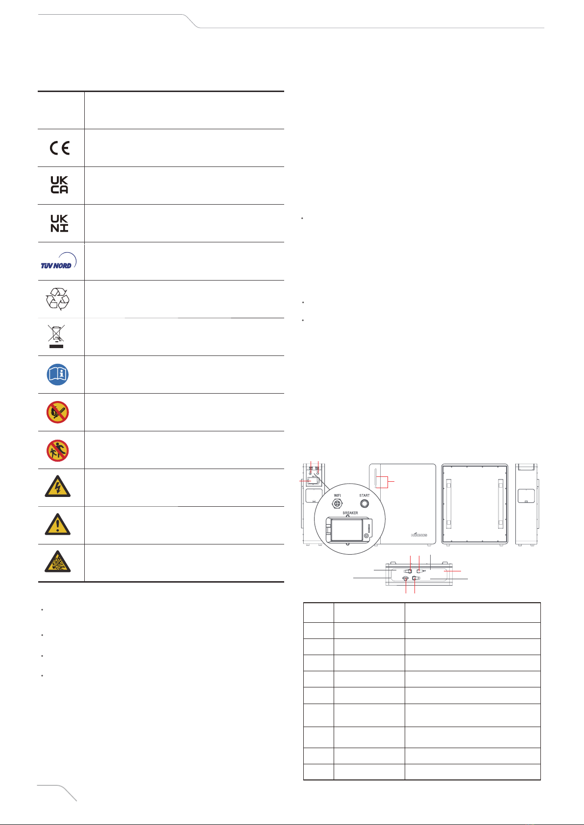
4.3 System Startup
Make sure all cables are connected properly prior to startup.
Open the protective cover of circuit breaker, and pull the circuit breaker to
ON position.
Press the startup button (auto-reset) for 2~3s, then SOC power indicator will
be on, which means battery pack is powered on normally. Wait for 1min after
startup is done (SOC indicator will flicker progressively during self-check of
system).
Disconnect the cable between battery pack and inverter, then disconnect the
short-circuit plug and cable on the last battery pack.
Move the inverter switch to the off position. Turn off the master battery pack
switch and disconnect the master battery pack breaker.
Hiconics will offer quality guarantee services within the warranty period if the
Product is installed and used by the Manual.
The warranty will expire immediately if the Product’s installation or operation
violates against the Manual
For any direct or indirect losses and damages due to the followings, we shall
not offer quality warranty services, nor undertake the direct or indirect
liabilities.
Please pack the BMS and battery module with original package. If package is
unavailable, please use the equivalent carton that conforms to the following
requirements.
Note: The table above is the recommended period for routine maintenance of
products. The actual maintenance period should be determined based on the
Product’s installation environment. Make sure to shorten the maintenance
period and increase maintenance frequency in case of dirty environment!
4.4 System Shutdown
Pull the circuit breaker to OFF position and finish battery shutdown. Do not
remove the power cable until the battery pack system is shut down complete-
ly; otherwise, arc discharge may occur, which may lead to severe injury. It is
suggested to touch the battery pack and cable 30s after system is shut down.
The battery should be opened, repaired or dismantled by workers or personnel
authorized by manufacturer only. For any consequences or liabilities due to
violation against the safety operation, design, production and equipment
safety standard, we do not bear any legal responsibilities.
5-Troubleshooting
6-Maintenance
7-Product Outage
8-Disclaimer
Troubleshooting
S/N Description
1
2
3
Power status indicator
of battery pack is off
Running status indica-
tor of power battery is
normally on in red
Running status indica-
tor of battery pack
flickers in yellow
Check if cable is connect-
ed properly and battery is
powered on
Check if PCS communi-
cation cable is connected
properly
Check if WiFi is
connected successfully
Troubleshooting
S/N Fault Description
1
2
Battery startup failure
Battery operation
failure
Check if cables are connect-
ed properly
Check if PCS cable is
connected properly and PCS
has alarm of battery com-
munication error
Maintenance
Period
Inspection
Contents Inspection Method
System
running and
environment 1 times/year
1.Visually inspect whether the
device has damage or deformation.
2.Check if there’s abnormal sound
while device is running.
3.Inspect the humidity and dust in
the ambient environment of device;
check if air inlet filters are normal.
4.The battery should be charged to
at least SOC 50 % each time
before battery is idled for over 9
months.
5.Please contact the dealer and
carry out reasonable evaluation
before expanding the capacity of
battery system.
Electric
connection 1 times/half
a year
1.Check if cable and terminal block
are loose and have the trace of arc
discharge and rust.
2.Check if cable has damage,
especially whether the surface that
contacts metal surface has the
trace of scratch.
2.Check if cable has damage,
especially whether the surface that
contacts metal surface has the
trace of scratch.
3.Check if the insulation wrapping
of cable terminal block is falling.
4.Check if cable distribution is
normal.
Applies to load above 80kg
With handle
The product can be wrapped completely
Force Majeure (earthquake, tsunami, fire hazard, etc.)
Misuse or non-compliance with regulations
Improper installation, debugging, startup or operation (violate against the
detailed guidance principle in installation manual)
The cooling and natural airflow are minimized due to insufficient
ventilation and circulation
Installed in corrosive environment
Damage during transport
Unauthorized maintenance
Poor maintenance of device. The device can be inspected by qualified
technicians at site after continuous use for 60 months. When the device
is used for over 60 months, the warranty request may be refused, unless
the device is proved to be fully maintained.
External factors, including abnormal physical or electrical pressure
(blackout surge, surge current, etc.)
Incompatible frequency converter or device
Connected to other brands of inverters without permission by Hiconics

Hiconics Eco-energy Drive Technology Co., Ltd.
Add: No.3 Boxing 2nd Road, E-Town, Daxing District, Beijing, China, 100176
Tel: +86 10 5918 0033 Fax: +86 10 5918 0035 Email: [email protected]
This manual suits for next models
1
Table of contents