Alpha ESS SMILE-B3 User manual

V08
Installation & Op
eration Manual
Energy Storage System (ESS)
SMILE-B3 (AU)


`
___________________________________________________________________
Alpha ESS Co., Ltd.
Page I of 61
Your Smart Energy
Imprint
Imprint(
Germany
Alpha ESS Europe GmbH
Tel.: +49 (0) 6103 459 160-1
E-mail: europe@alpha-ess.de
Website: www.alpha-ess.de
Add.: Paul-Ehrlich-Straße 1a
63225 Langen
China
Alpha ESS Co., Ltd.
Tel.: +86 (0) 513 806 868 91
E-mail: info@alpha-ess.com
Website: www.alpha-ess.com
Add.: Jiu Hua Road 888, High-Tech Industrial Development Zone, Nantong City, 226300, Jiangsu
Province
Australia
Alpha ESS Australia Pty. Ltd.
Tel.: +61 1300 968 933
E-mail: australia@alpha-ess.com
Website: www.alpha-ess.com.au
Add.: Suite 1, Level 1, 530 Botany Road, Alexandria, NSW
Italy
Alpha ESS Italy S.r.l.
Tel.: +39 (0)599 239 50
E-mail: info@alpha-ess.it
Web: https://it.alpha-ess.com/
Add: Via Loda, 17-41013 Castelfranco Emilia (MO)
July 29th, 2019

`
___________________________________________________________________
Alpha ESS Co., Ltd.
Page II of 61
Your Smart Energy
Copyright Declaration
Copyright(Declaration(
The copyright of this manual is owned by Alpha ESS Co., Ltd. (hereinafter referred to as "AlphaESS")
and all rights are reserved. Please keep the manual properly and operate strictly according to all safety
and operation instructions in this manual. Do not operate the system before reading the manual.
Version(Information(
Version
Date
Contents
V08
08072020
Only suitable in Australia and New Zealand

`
___________________________________________________________________
Alpha ESS Co., Ltd.
Page III of 61
Your Smart Energy
Contents
Contents(
Imprint ........................................................................................................................................... I
Copyright Declaration ................................................................................................................ II
Version Information .................................................................................................................... II
Contents ..................................................................................................................................... III
1. Introduction ............................................................................................................................ 5
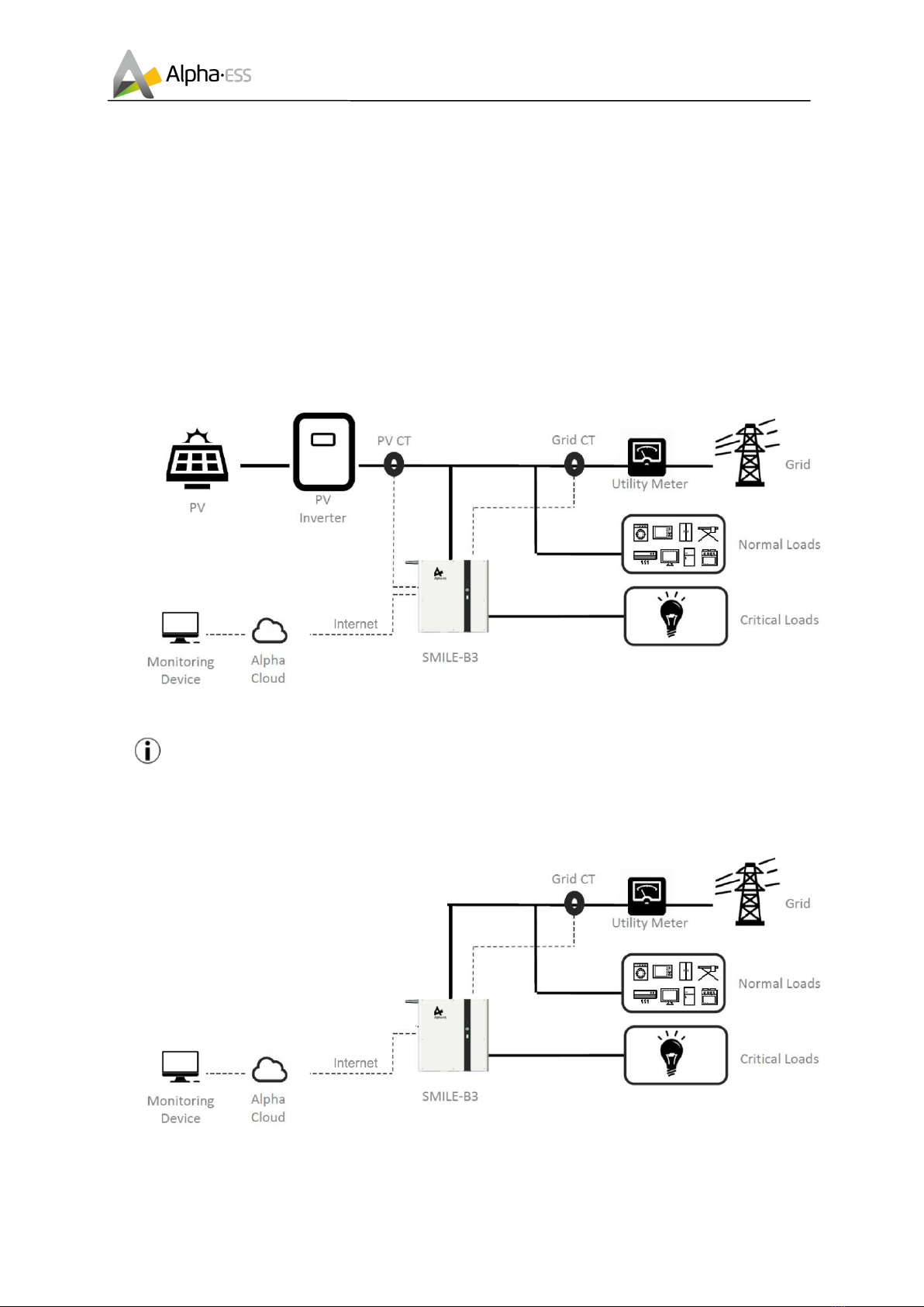
1.1 Introduction of System .................................................................................................. 5
1.2 General Precautions ...................................................................................................... 6
2. Installation .............................................................................................................................. 8
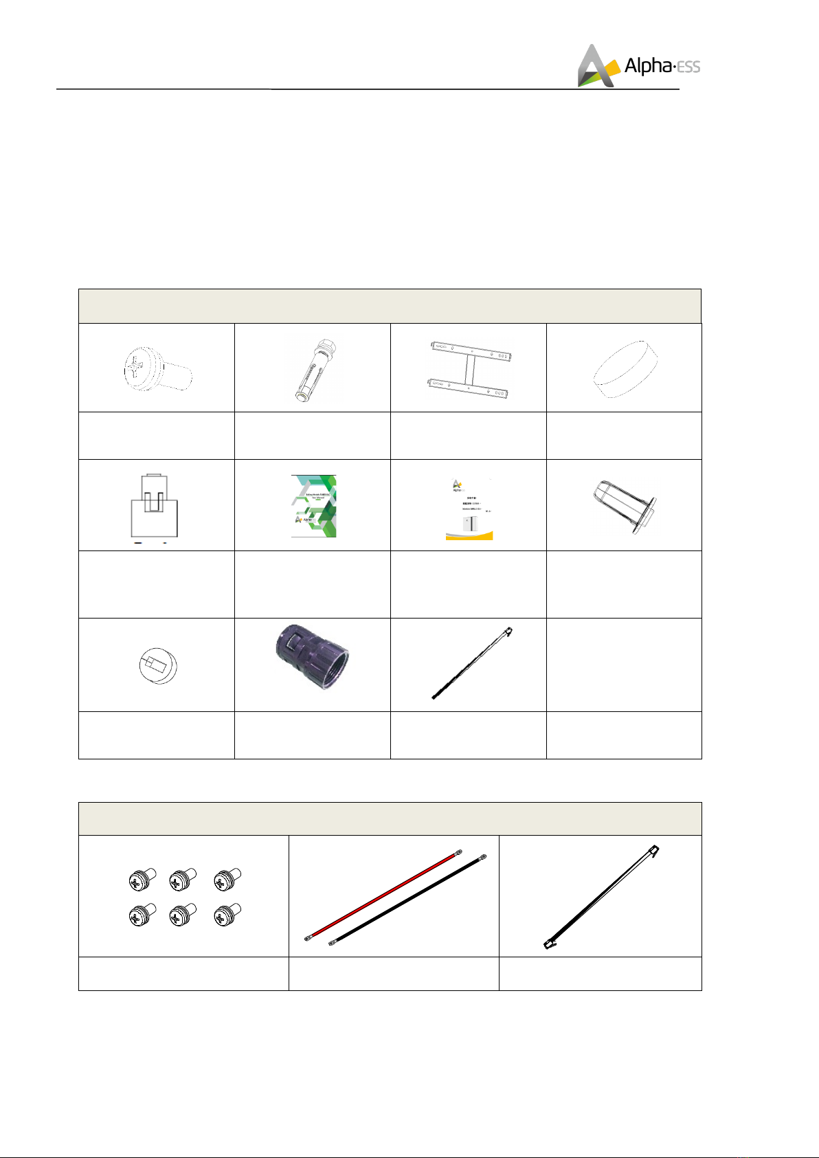
2.1 Parts List ......................................................................................................................... 8
2.2 System Appearance ....................................................................................................... 9
2.3 Limitation of Liability ................................................................................................... 12
2.4 System Installation ...................................................................................................... 13
2.4.1 Installation Site and Environment ................................................................... 13
2.4.2 Installation Tools ............................................................................................. 14
2.4.3 SMILE-B3 Installation ..................................................................................... 15
2.4.4 Battery Expansion .......................................................................................... 20
2.4.5 Electricity Meter Wiring .................................................................................. 28
3. Operation .............................................................................................................................. 35
3.1 Switch on ...................................................................................................................... 35
3.2 Switch off ...................................................................................................................... 35
3.3 Emergency Procedure ................................................................................................. 35
3.3.1 Emergency Handling Plan .............................................................................. 35
3.3.2 Hazards .......................................................................................................... 36
3.3.3 Fire ................................................................................................................. 36
4. Maintenance ......................................................................................................................... 37
5. WiFi Module Configuration ................................................................................................. 37
6. System Registration ............................................................................................................ 41
6.1 System Setup in Monitoring ....................................................................................... 42
6.1.1 Basic Information ........................................................................................... 42
6.1.2 Meter Information ........................................................................................... 42
6.1.3 Inverter Information ........................................................................................ 43
6.1.4 Other Information ........................................................................................... 44
7. On-line Monitoring ............................................................................................................... 45
7.1 Account Registration ................................................................................................... 45


`
Alpha ESS Co., Ltd.
Page 5 of 61
Your Smart Energy
Introduction
1. Introduction
1.1 Introduction(of(System(
SMILE-B3 is an AC coupled all-in-one battery energy storage system (BESS). It can help to achieve the
optimal usage of renewable energy. SMILE-B3 can control the bi-directional flow of electric power, work
under auto/manual & time-of-use (TOU) modes, charge/discharge the battery as per customer’s setting.
Under the auto mode, SMILE-B3 will store surplus renewable energy onto the battery and discharge
battery to supply power to local loads when renewable energy is not enough. SMILE-B3 is equipped
with 3 buttons, friendly human machine interaction system. More importantly SMILE-B3 is stable, safe,
and reliable. The standard schematic is as shown in Figure 1.1:
Figure 1.1 SMILE-B3 System with PV
NOTE: For the AC coupled system with PV, if only installing Grid CT, the system cannot
display PV Inverter generated power, electric energy production etc.
If there is no PV, the schematic is as below:
Figure 1.2 SMILE-B3 System without PV
___________________________________________________________________

`
___________________________________________________________________
Alpha ESS Co., Ltd.
Page 6 of 61
Your Smart Energy
Introduction
1.2 General(Precautions(
Danger:
Danger to life due to high voltages of battery and electric shock.
ØDo not touch uninsulated cable termination.
ØDo not touch the DC wires.
ØDo not open the inverter and battery.
ØDo not use wet cloth to wipe the system.
ØDo not dispose of batteries in fire. The batteries may explode!
ØOnly qualified personnel who are equipped with the corresponding skills can install and debug
the system. Before performing any work on the inverter or battery pack, please disconnect the
inverter from all voltage sources as described in this document.
Warning
Risks of chemical burn electrolyte or toxic gases.
During standard operation, electrolyte won't leak from the battery pack as well as form of
toxic gases. Even if the battery was handled with care, but if the battery pack is damaged or
breaks down, electrolyte may leak or form toxic gases.
ØDo not install the system in temperature or humidity exceeding the permitted range.
ØPlease do not use wet hands to touch the system.
ØDo not place heavy objects on the top of the system.
ØDo not damage the system using sharp objects.
ØDo not install or operate the system in the inflammable and explosive environment or high
humidity environment.
ØDo not install explosive gas and the battery pack in the area that containing highly flammable
substance or gas.
ØIf the moisture penetrates the system (e.g. due to casing damage), please do not install or
operate the system.
ØWhen the system has connected the extended battery module, please do not move the system.
ØUse strapping if necessary during transportation to prevent tipping.
ØSMILE-B3 transport must be conducted by the manufacturer or professionals, these
operations should be recorded and used.
ØCertified ABC extinguishers with minimum capacity 2 kg must be carried during transportation.
ØNo smoking during unloading of vehicles and close to them.
ØIf you want to replace the battery module, please pack new dangerous packaging according to
needs, pack them and let the supplier receive them.
ØIf contacting with the electrolyte, please wash affected area with water immediately, and consult
a doctor immediately.

`
___________________________________________________________________
Alpha ESS Co., Ltd.
Page 7 of 61
Your Smart Energy
Introduction
Risk of injury by hoisting or falling system
Inverters and batteries are heavy and can cause personal injury if the inverter or battery is
improperly lifted or dropped during transport or when attached or removed from walls.
Lifting and transporting SMILE-B3 is conducted by more than 1 person.

`
___________________________________________________________________
Alpha ESS Co., Ltd.
Page 8 of 61
Your Smart Energy
Installation
2. Installation
2.1 Parts(List(
Check the following parts list for completeness.
AlphaESS provides a complete set of system for on-site customers, including:
Table 1 Parts List of B3
SMILE-B3
1 x M4*12 screw
4 x Expansion screw
1 x Installing support
8 x White plug
2 x CT
(100A, 3000:1)
(1 x CT for DE
version)
1 x Battery user
manual
1x Installation manual
1 x WiFi module
(optional /
Standard for AU
version)
2x Gum-elastic ring
2x M25 Pipe joint
(AU version)
1x 5m Net cable
(AU version)
Table 2 Parts List of Battery Expansion Accessory Package
SMILE-B3 Battery Expansion Accessories (Optional, Standard for DE Version)
6 x Screw M5*10
1 x Positive power line
2 x Negative power line
1 x Battery communication
cable

`
___________________________________________________________________
Alpha ESS Co., Ltd.
Page 9 of 61
Your Smart Energy
Installation
1 x Installing positioner
2 x Stand holder
2 x M6*10
2.2 System(Appearance(
Figure 2.1 SMILE-B3 Exterior View Table 3
SMILE-B3 System LED Display
LED
Status
Description
normal
Normally on: Normal system operation
Single flicker: system standby or self-
inspection
off: out-of-order
fault
off: fault-free
Normally on: out-of-order

`
___________________________________________________________________
Alpha ESS Co., Ltd.
Page 10 of 61
Your Smart Energy
Installation
com
Normally on: Normal network connection
Flicker: connecting to the server
off: un-connected network
Table 4 SMILE-B3 Battery LED Display
SOC Status
Description
SOC Instruction
SOC<5%
5%=<SOC<25%
25%=<SOC<50%
50%=<SOC<75%
75%=<SOC<95%
SOC>95%
LED Outer Ring Light
Flicker Status
Standby: green light flickers for 1s
Work: green light flickers for 10s
Table 5 SMILE-B3 WIFI (Yilian) Display
LED
Status
Description
Red
Normally on: normally communicate with
EMS
Off: not connected to EMS
Green
Flickers once in 30s : not connected to
router
Flickers 3 times in 30s: not connected to
server
Normally on: normal communication with
server
Normally on after flickering: sending or
data to server

`
___________________________________________________________________
Alpha ESS Co., Ltd.
Page 11 of 61
Your Smart Energy
Installation
Figure 2.2 SMILE-B3 Front View
Figure 2.3 SMILE-B3 Left View
Note: COM1/COM2/COM3 can be passed through by two net cables.

`
Alpha ESS Co., Ltd.
Page 12 of 61
Your Smart Energy
Installation
Figure 2.4 SMILE-B3 Rear View
2.3 Limitation(of(Liability(
AlphaESS shall not be liable directly or indirectly for any product damage or property loss caused by
any of the following conditions.
The product has been modified, the design modification or the change of parts without the authorization
of AlphaESS;
Non-AlphaESS technicians change, repair and serial number removing;
System design and installation fail to meet the standards and other relevant requirements;
Fail to observe local safety regulations;
Transportation damage (including paint scratches caused by friction in packaging during transportation).
Once the container/package is unloaded and the damage is confirmed, claims shall be put forward
directly to the transport or insurance company;
Fail to comply with any/all user manuals, installation guide and maintenance rules;
Improperness or misuse of equipment;
Insufficient equipment ventilation;
Product maintenance procedures do not follow acceptable standards;
Force majeure (violent or stormy weather, thunder and lightning, overvoltage, fire, etc.);
Any damage caused by external factors
___________________________________________________________________

`
___________________________________________________________________
Alpha ESS Co., Ltd.
Page 13 of 61
Your Smart Energy
Installation
2.4 System(Installation((
This manual introduces the basic steps how to install and set up SMILE-B3.
Observe the specified minimum distance of adjacent objects;
Minimum distance guarantee;
Sufficient heat dissipation;
The upper cover of the energy storage system has enough space to open;
Sufficient room for maintenance.
Figure 2.5 Limit the Distance to an Adjacent Object
!"#"$ %&'()**)(+,&-.+(/-)&0-1&2+3,&4/&(-
The following sites are not allowed installation:
a. wall cavities;
b. on roofs not specifically deemed suitable;
c. areas of access/egress;
d. under stairways;
e. under access walkways;
f. sites where the freezing point is reached, like garages, carports or other places;
g. sites with humidity and condensation above 85%.
h. Places with plenty of salt.
i. Flooded areas.
j. Earthquake areas-additional security measures are needed here.
k. Places with altitude higher than 2,000 meters.

`
___________________________________________________________________
Alpha ESS Co., Ltd.
Page 14 of 61
Your Smart Energy
Installation
l. Place with explosive gases.
m. Place with direct sunlight.
n. Place with the ambient temperature extremely variable.
o. Places with highly flammable materials or gases.
p. Wet rooms
q. Places with potentially explosive gases.
r. Wall load bearing must exceed 180kg
Note: Please neglect the rules from a to e if system will be installed at other country rather
than AUS and NZL.
!"#"! %&'()**)(+,&-5,,*'-
The following tools are required to install the equipment.
Wire
Cutter
Cable clamp
Screw Driver
Set
T20 double offset ring
spanner
Percussion Drilling
NOTE: Use properly insulated tools to prevent accidental electric shock or short circuits. If
insulated tools are not available, cover the entire exposed metal surfaces of the available tools,
except their tips, with electrical tape.
2.4.2.1 Safety Gear
It is recommended to wear the following safety gear when dealing with the battery pack

`
___________________________________________________________________
Alpha ESS Co., Ltd.
Page 15 of 61
Your Smart Energy
Installation
!"#"6 .7%819:6-%&'()**)(+,&-
Figure 2.6 Remove SMILE-B3 Packaging
Step 1: Take out SMILE-B3 from the packaging box, as shown in Figure 2.6.
Figure 2.7 Remove SMILE-B3 Upper Cover Plate
Step 2: Use the T20 double offset ring spanner to unscrew the screws, as shown in
Figure 2.7.
Note: the internal 63A and the external 80A breaker must be in off position to
prevent short circuit.
In any case, the first step after
unpacking is to keep the
breaker of 63A and 80A in off
position.

`
___________________________________________________________________
Alpha ESS Co., Ltd.
Page 16 of 61
Your Smart Energy
Installation
Figure 2.8 Stand Positioning
Step 3: use the percussion drill (M12 drill) to drill holes in the wall (there are two
methods to position the holes), then install and place the stand. Firstly insert the
expansion pipe into the drilled hole. Then pass the tapping screw through the spacer
and tighten it with the cross screwdriver, as shown in Figure 2.8.
Figure 2.9 Casing Fixation
Step 4: install the casing of SMILE-B3 (hold the two arrow positions of B3 and install
the B3 box to the stand) , as shown in Figure 2.9.
Figure 2.10 Earthing Connectting Position

`
___________________________________________________________________
Alpha ESS Co., Ltd.
Page 17 of 61
Your Smart Energy
Installation
Step 5: the earthing connecting position for SMILE-B3 is as shown in Figure 2.10,
please use the M4 screw.
Figure 2.11 Backup and Grid Wire Harness Wiring
Step 6: Connect Backup and Grid wire harness as shown in Figure 2.11.
Note: in Australia, the neutral of backup and grid circuit should be externally
connected on the neutral bar.
Note: in some places like AUS and NZL the corrugated pipes will be needed. Please
remove the original gum-elastic rings and the connectors of Backup and Grid port
waterproof contact and then replace them with the M25 pipe joints and the gum-elastic
rings in parts list.
The suggested torque for the waterproof contact is 3.75 N.m±10%.

`
___________________________________________________________________
Alpha ESS Co., Ltd.
Page 18 of 61
Your Smart Energy
Installation
Figure 2.12 CT Wire Harness Wiring
Step 7: Complete for installing CT, as shown in Figure 2.12.
Note: CT communication wires can be connected directly through the gum-elastic
ring of the M25 waterproof contact, no need to make the on-site network line.
Other manuals for SMILE-B3
1
Table of contents
Other Alpha ESS Batteries Pack manuals
Popular Batteries Pack manuals by other brands

Ryobi
Ryobi OP40602 Operator's manual

rollease acmeda
rollease acmeda AUTOMATE instruction manual

RedEarth
RedEarth SunRise SRS-3 Series installation manual

BYD
BYD Battery-Box Pro series Installation guidance

UV Systems
UV Systems Dual TripleBright II Warranty and instructions

Solplanet
Solplanet Ai-HB G2 Series Quick installation guide