Alpha Outback Energy SPCIII-7200-48 User manual

User Manual
SPCIII-7200-48
7.2kW
SOLAR INVERTER / CHARGER

Table of Contents
ABOUT THIS MANUAL .................................................................................................................................................. 1
Purpose ................................................................................................................................................1
Scope ...................................................................................................................................................1
SAFETY INSTRUCTIONS .............................................................................................................................................. 1
INTRODUCTION ............................................................................................................................................................. 2
Features................................................................................................................................................2
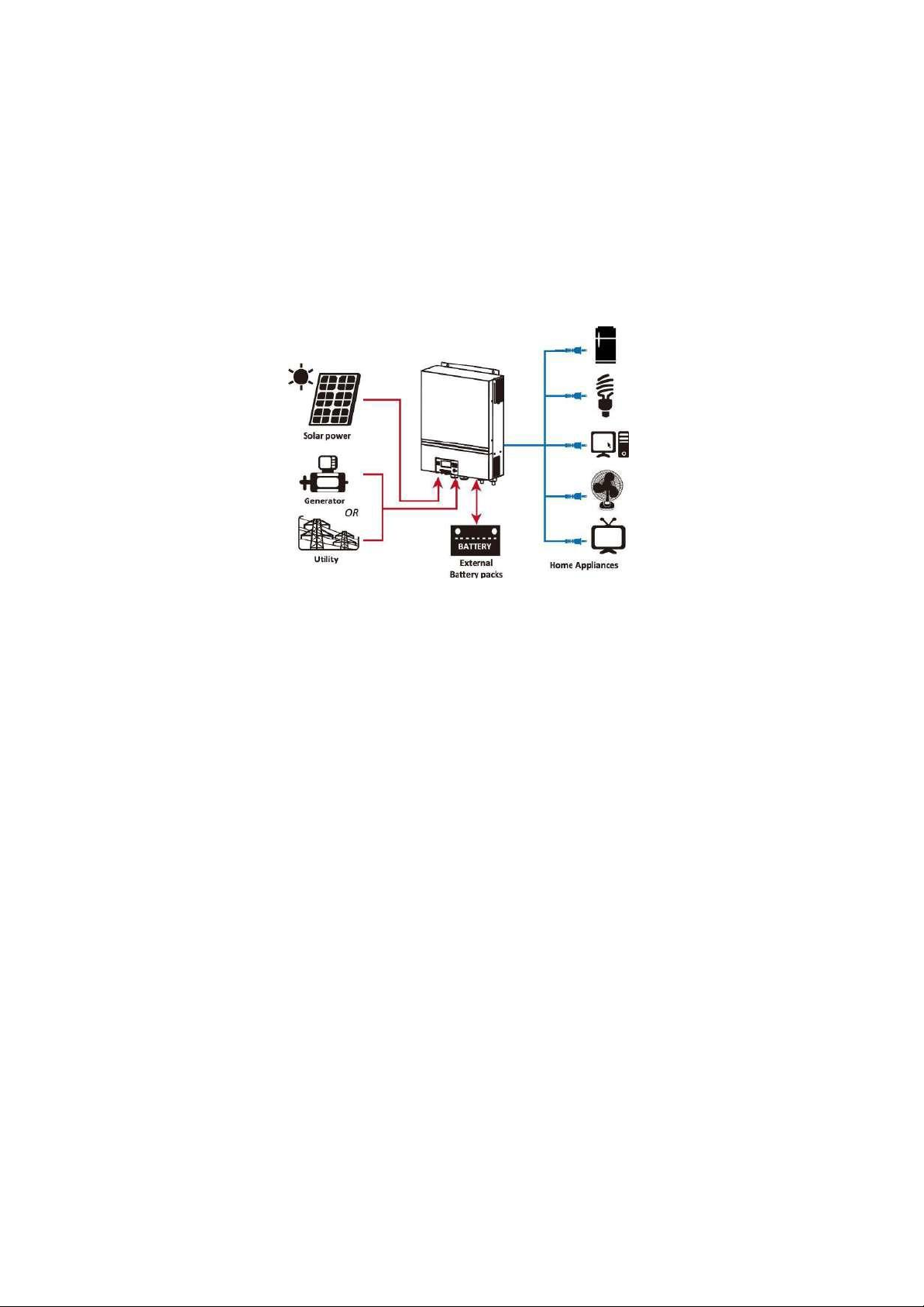
Basic System Architecture.......................................................................................................................3
Product
Overview
...................................................................................................................................4
INSTALLATION ............................................................................................................................................................... 5
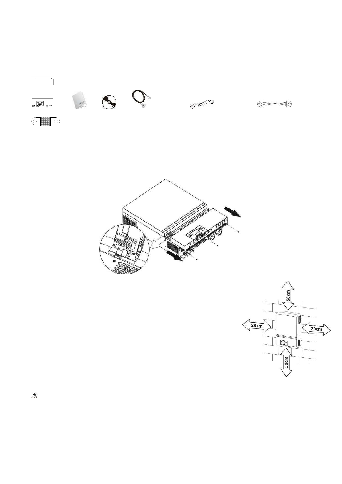
Unpacking and Inspection.......................................................................................................................
5
Preparation............................................................................................................................................5
Mounting the Unit ..................................................................................................................................5
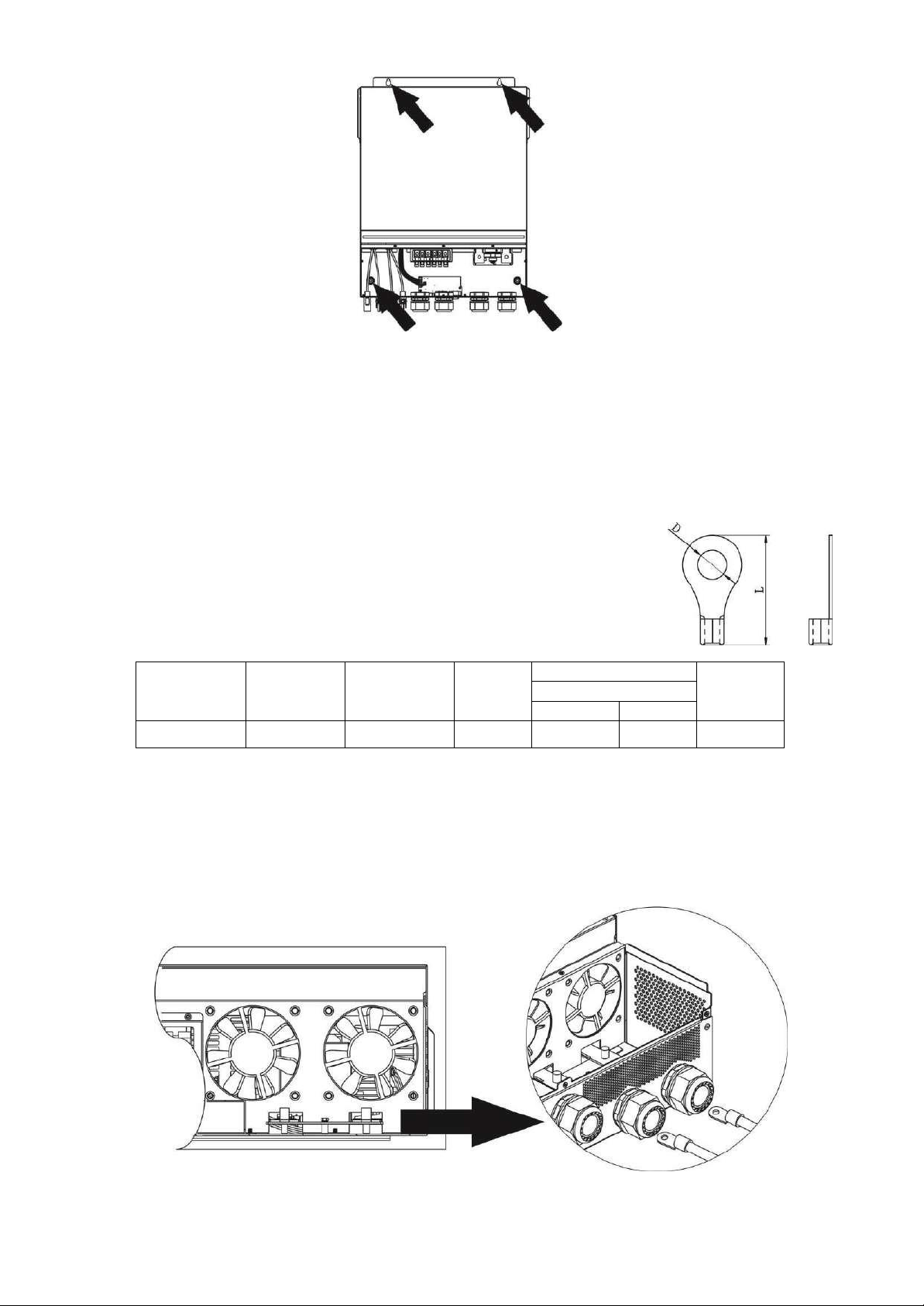
Battery Connection.................................................................................................................................
6
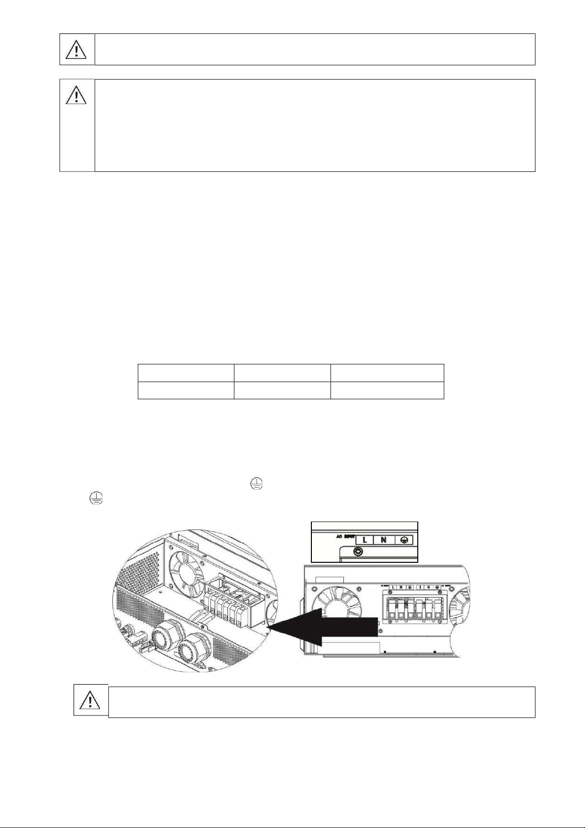
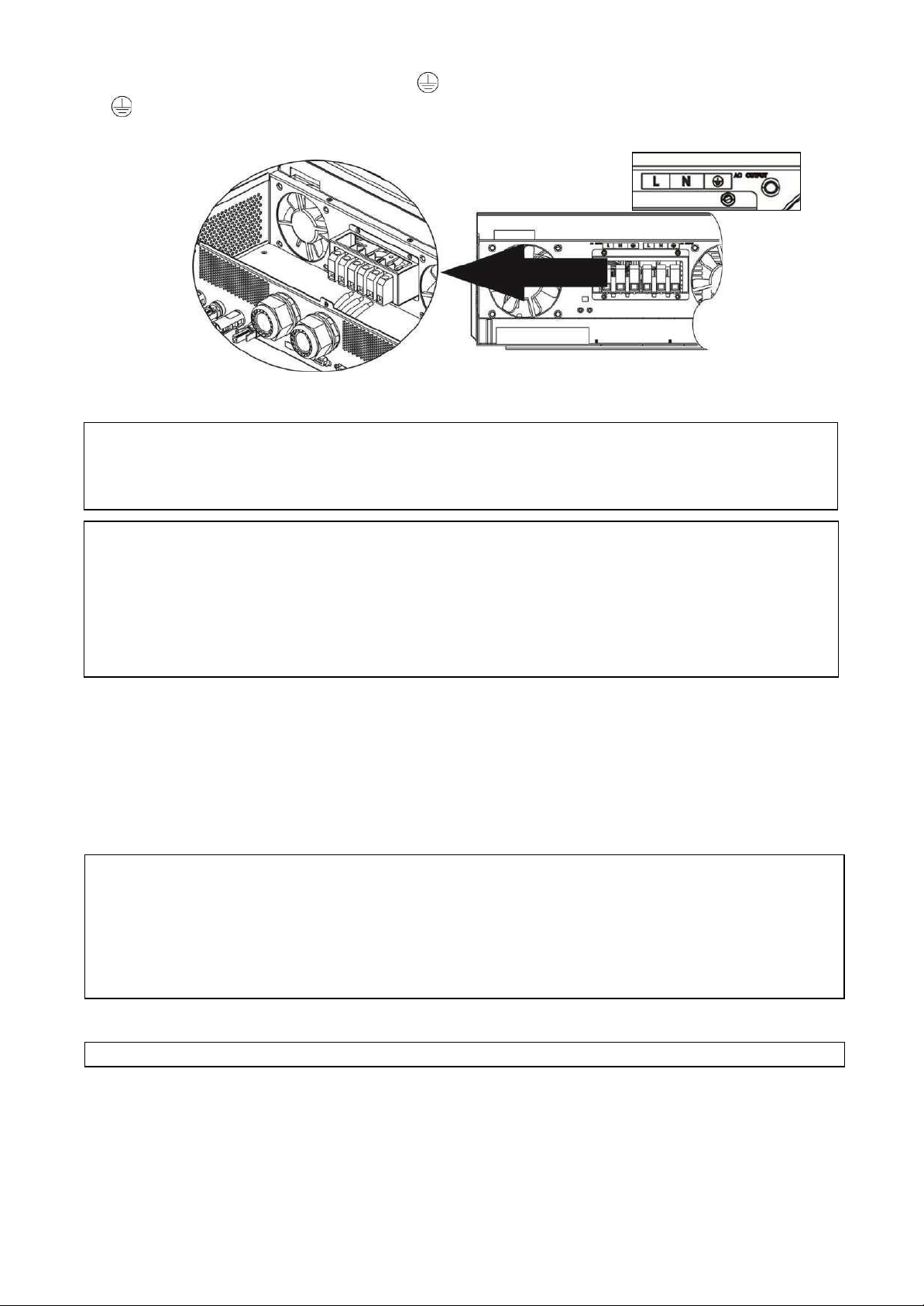
AC Input/Output Connection...................................................................................................................7
PV Connection .......................................................................................................................................8
Final Assembly.....................................................................................................................................11
Remote Display Panel Installation.......................................................................................................... 11
Communication
Connection................................................................................................................... 13
Dry Contact Signal ...............................................................................................................................13
BMS
Communication
..............................................................................................................................13
OPERATION ...................................................................................................................................................................14
Power ON/OFF.....................................................................................................................................14
Inverter Turn-on ..................................................................................................................................14
Operation and Display Panel .................................................................................................................15
LCD Display Icons ................................................................................................................................16
LCD
Setting
..........................................................................................................................................18
LCD Display.........................................................................................................................................34
Operating Mode Description..................................................................................................................39
Faults Reference Code..........................................................................................................................42
Warning Indicator ................................................................................................................................43
BATTERY EQUALIZATION .........................................................................................................................................44
SPECIFICATIONS .........................................................................................................................................................45
Table 1 Line Mode Specifications ...........................................................................................................45
Table 2 Inverter Mode Specifications......................................................................................................46
Table 3 Charge Mode Specifications.......................................................................................................47
Table 4 General Specifications ...............................................................................................................48
TROUBLE
SHOOTING
...................................................................................................................................................49
Appendix I: Parallel function (Only for Parallel mode) ..................................................................................50
Appendix II: BMS Communication Installation.................................................................................................62
Appendix III: The Wi-FiOperation Guide in Remote
Panel
..........................................................................70

1
ABOUT THIS MANUAL
Purpose
This manual describes the assembly, installation, operation and troubleshooting of this unit. Please read
this manual carefully before installations and operations. Keep this manual for future reference.
Scope
This manual provides safety and installation guidelines as well as information on tools and wiring.
SAFETY INSTRUCTIONS
WARNING: This chapter contains important safety and operating instructions. Read and
keep this manual for future reference.
1.
Before using the unit, read all instructions and cautionary markings on the unit, the batteries and all
appropriate sections of this manual.
2.
CAUTION --To reduce risk of injury, charge only deep-cycle lead acid type rechargeable batteries.
Other types of batteries may burst, causing personal injury and damage.
3.
Do not disassemble the unit. Take it to a qualified service center when service or repair is required.
Incorrect re-assembly may result in a risk of electric shock or fire.
4.
To reduce risk of electric shock, disconnect all wirings before attempting any maintenance or cleaning.
Turning off the unit will not reduce this risk.
5.
CAUTION –Only qualified personnel can install this device with battery.
6.
NEVER charge a frozen battery.
7.
For optimum operation of this inverter/charger, please follow required spec to select appropriate cable
size. It’s very important to correctly operate this inverter/charger.
8.
Be very cautious when working with metal tools on or around batteries. A potential risk exists to drop
a tool to spark or short circuit batteries or other electrical parts and could cause an explosion.
9.
Please strictly follow installation procedure when you want to disconnect AC or DC terminals. Please
refer to INSTALLATION section of this manual for the details.
10.
Fuses are provided as over-current protection for the battery supply.
11.
GROUNDING INSTRUCTIONS -This inverter/charger should be connected to a permanent grounded
wiring system. Be sure to comply with local requirements and regulation to install this inverter.
12.
NEVER cause AC output and DC input short circuited. Do NOT connect to the mains when DC input
short circuits.
13.
Warning!! Only qualified service persons are able to service this device. If errors still persist after
following troubleshooting table, please send this inverter/charger back to local dealer or service center
for maintenance.
14.
WARNING: Because this inverter is non-isolated, only three types of PV modules are acceptable:
single crystalline, poly crystalline with class A-rated and CIGS modules. To avoid any malfunction, do
not connect any PV modules with possible current leakage to the inverter. For example, grounded PV
modules will cause current leakage to the inverter. When using CIGS modules, please be sure NO
grounding.
15.
CAUTION: It’s required to use PV junction box with surge protection. Otherwise, it will cause damage
on inverter when lightning occurs on PV modules.

2
INTRODUCTION
This is a multi-function inverter, combining functions of inverter, solar charger and battery charger to offer
uninterruptible power support in a single package. The comprehensive LCD display offers user-configurable
and easy-accessible button operations such as battery charging current, AC or solar charging priority, and
acceptable input voltage based on different applications.
Features
Pure sine wave inverter
Configurable color with the built-in RGB LED bar
Built-in Wi-Fi for mobile monitoring (APP is required)
Supports USB On-the-Go function
Built-in anti-dusk kit
Detachable LCD control module with multiple communication ports for BMS (RS485, CAN-BUS, RS232)
Configurable input voltage ranges for home appliances and personal computers via LCD control panel
Configurable AC/PV output usage timer and prioritization
Configurable AC/Solar charger priority via LCD control panel
Configurable battery charging current based on applications via LCD control panel
Compatible to utility mains or generator power
Auto restart while AC is recovering
Overload / Over temperature / short circuit protection
Smart battery charger design for optimized battery performance
Cold start function

3
Basic System Architecture
The following illustration shows basic application for this unit. It also includes the following devices to have a
complete running system:
Generator or Utility mains.
PV modules
Consult with your system integrator for other possible system architectures depending on your requirements.
This inverter can power various appliances in home or office environment, including motor-type appliances
such as tube light, fan, refrigerator and air conditioners.
Figure 1 Basic hybrid PV System Overview
Depending on different power situations, this hybrid inverter is designed to generate continuous power from PV
solar modules (solar panels), battery, and the utility. When MPP input voltage of PV modules is within
acceptable range (see specification for the details), this inverter is able to generate power to offset the grid
(utility) and charge battery. The galvanic isolation between Battery and AC output, allow the user to use any
battery grounding schema with this hybrid inverter. See Figure 1 for a simple diagram of a typical solar system
with this hybrid inverter.

4
3.6KW
7.2KW
Product Overview
NOTE: For parallel model installation and operation, please check
Appendix I.
1.
LCD display
2.
Status indicator
3.
Charging indicator
4.
Fault indicator
5.
Function buttons
6.
Power on/off switch
7.
AC input connectors
8.
AC output connectors (Load connection)
9.
PV connectors
10.
Battery connectors
11.
Remote LCD module communication port
12.
Parallel communication port
13.
Current sharing port
14.
Dry contact
15.
USB port as USB communication port and USB function port
16.
BMS communication port: CAN, RS-485 or RS-232
17.
N/A
18.
RS-232 communication port
19.
RGB LED bar (refer to LCD Setting section for the details)

5
INSTALLATION
Unpacking and Inspection
Before installation, please inspect the unit. Be sure that nothing inside the package is damaged. You should
have received the following items inside of package:
Inverter unit Manual software CD RS-232 cable Parallel communication cable Current sharing cable
DC Fuse
Preparation
Before connecting all wirings, please take off bottom cover by removing two screws. When removing the
bottom cover, be carefully to remove three cables as shown below.
Mounting the Unit
Consider the following points before selecting where to install:
Do not mount the inverter on flammable construction materials.
Mount on a solid surface
Install this inverter at eye level in order to allow the LCD display to be read
at all times.
The ambient temperature should be between 0°C and 55°C to ensure
optimal operation.
The recommended installation position is to be adhered to the wall
vertically.
Be sure to keep other objects and surfaces as shown in the right diagram
to guarantee sufficient heat dissipation and to have enough space for
removing wires.
SUITABLE FOR MOUNTING ON CONCRETE OR OTHER NON-COMBUSTIBLE SURFACE ONLY.

6
Install the unit by screwing four screws. It’s recommended to use M4 or M5 screws.
Battery Connection
CAUTION: For safety operation and regulation compliance, it’s requested to install a separate DC over-current
protector or disconnect device between battery and inverter. It may not be requested to have a disconnect
device in some applications, however, it’s still requested to have over-current protection installed. Please refer
to typical amperage in below table as required fuse or breaker size.
Ring terminal:
WARNING! All wiring must be performed by a qualified personnel.
WARNING! It's very important for system safety and efficient operation to use
appropriate cable for battery connection. To reduce risk of injury, please use the
proper recommended cable and terminal size as below.
Recommended battery cable gauge and terminal size:
Typical
Amperage
Battery
capacity
AWG no.
Section
Ring Terminal
Torque
Dimensions
D (mm)
L (mm)
165ADC
250Ah
1*1/0AWG
50 mm2
8.4
47
5 Nm
Please follow below steps to implement battery connection:
1.
Assemble battery ring terminal based on recommended battery cable and terminal size.
2.
Insert the ring terminal of battery cable flatly into battery connector of inverter and make sure the nuts are
tightened with torque of 5 Nm. Make sure polarity at both the battery and the inverter/charge is correctly
connected and ring terminals are tightly screwed to the battery terminals.

7
AC Input/Output Connection
CAUTION!! Before connecting to AC input power source, please install a separate AC breaker between
inverter and AC input power source. This will ensure the inverter can be securely disconnected during
maintenance and fully protected from over current of AC input.
CAUTION!! There are two terminal blocks with “IN” and “OUT” markings. Please do NOT mis-connect input
and output connectors.
WARNING! All wiring must be performed by a qualified personnel.
WARNING! It's very important for system safety and efficient operation to use appropriate cable for AC input
connection. To reduce risk of injury, please use the proper recommended cable size as below.
Suggested cable gauge requirement for AC wires
AWG no.
Section
Torque Value
8 AWG
10 mm2
1.4 ~ 1.6Nm
Please follow below steps to implement AC input/output connection:
1.
Before making AC input/output connection, be sure to open DC protector or disconnector first.
2.
Remove insulation sleeve 10mm for six conductors. And shorten phase L and neutral conductor N 3 mm.
3.
Insert AC input wires according to polarities indicated on terminal block and tighten the terminal screws. Be
sure to connect PE protective conductor ( ) first.
→Ground (yellow-green)
L→LINE (brown or black)
N→Neutral (blue)
WARNING:
Be sure that AC power source is disconnected before attempting to hardwire it to the unit.
CAUTION!! Do not place anything between the flat part of the inverter terminal and the ring
terminal. Otherwise, overheating may occur.
CAUTION!! Do not apply anti-oxidant substance on the terminals before terminals are connected
tightly.
CAUTION!! Before making the final DC connection or closing DC breaker/disconnector, be sure
positive (+) must be connected to positive (+) and negative (-) must be connected to negative (-).
WARNING: Shock Hazard
Installation must be performed with care due to high battery voltage in series.

8
CAUTION: Important
Be sure to connect AC wires with correct polarity. If L and N wires are connected reversely, it may cause
utility short-circuited when these inverters are worked in parallel operation.
CAUTION: Appliances such as air conditioner requires at least 2~3 minutes to restart because it’s required
to have enough time to balance refrigerant gas inside of circuits. If a power shortage occurs and recovers
in a short time, it will cause damage to your connected appliances. To prevent this kind of damage, please
check manufacturer of air conditioner if it’s equipped with time-delay function before installation. Otherwise,
this inverter/charger will be trigger overload fault and cut off output to protect your appliance but sometimes
it still causes internal damage to the air conditioner.
WARNING: Because this inverter is non-isolated, only three types of PV modules are acceptable: single
crystalline and poly crystalline with class A-rated and CIGS modules.
To avoid any malfunction, do not connect any PV modules with possible current leakage to the inverter. For
example, grounded PV modules will cause current leakage to the inverter. When using CIGS modules, please
be sure NO grounding.
CAUTION: It’s required to use PV junction box with surge protection. Otherwise, it will cause damage on
inverter when lightning occurs on PV modules.
CAUTION: Exceeding the maximum input voltage can destroy the unit!! Check the system before wire connection.
4.
Then, insert AC output wires according to polarities indicated on terminal block and tighten terminal screws.
Be sure to connect PE protective conductor ( ) first.
→Ground (yellow-green)
L→LINE (brown or black)
N→Neutral (blue)
5.
Make sure the wires are securely connected.
PV Connection
CAUTION: Before connecting to PV modules, please install separately DC circuit breakers between inverter
and PV modules.
NOTE1: Please use 600VDC/30A DC circuit breaker.
NOTE2: The overvoltage category of the PV input is II. External surge arresters are strongly recommended.
Please follow the steps below to implement PV module connection:
Step 1: Check the input voltage of PV array modules. This system is applied with two strings of PV array. Please
make sure that the maximum current load of each PV input connector is below 18A.
Step 2: Disconnect the circuit breaker and switch off the DC switch.

9
CAUTION: Never directly touch the terminals of inverter. It might cause lethal electric shock.
Step 3: Assemble provided PV connectors with PV modules by the following steps.
Components for PV connectors and Tools:
Female connector housing
Female terminal
Male connector housing
Male terminal
Crimping tool and spanner
Prepare the cable and follow the connector assembly process:
Strip one cable 8 mm on both end sides and be careful NOT to nick conductors.
Insert striped cable into female terminal and crimp female terminal as shown below.
Insert assembled cable into female connector housing as shown below.
Insert striped cable into male terminal and crimp male terminal as shown below.
Insert assembled cable into male connector housing as shown below.
Then, use spanner to screw pressure dome tightly to female connector and male connector as shown below.
Step 4: Check correct polarity of connection cable from PV modules and PV input connectors. Then, connect
positive pole (+) of connection cable to positive pole (+) of PV input connector. Connect negative pole (-) of
connection cable to negative pole (-) of PV input connector.
WARNING! For safety and efficiency, it's very important to use appropriate cables for PV module connection.
To reduce risk of injury, please use the proper cable size as recommended below.
Suggested cable gauge requirement for PV cables:
AWG no.
Section
10~12 AWG
4~6 mm2

10
CAUTION: for input voltages below 250Vdc the PV power may be limited by the Max PV Input current.
Recommended Panel Configuration
When selecting proper PV modules, please be sure to consider the following parameters:
1.
Open circuit Voltage (Voc) of PV modules not to exceed maximum PV array open circuit voltage of the
inverter.
2.
Open circuit Voltage (Voc) of PV modules should be higher than the start-up voltage.
Max. PV Array Power
8000W (2x 4000W)
Max. PV Array Open Circuit Voltage
500Vdc
PV Array MPPT Voltage Range
90Vdc~450Vdc
Start-up Voltage (Voc)
80Vdc
Recommended solar panel configuration:
Solar Panel Spec.
(reference)
- 250Wp
-
Vmp: 30.7Vdc
-
Imp: 8.3A
-
Voc: 37.7Vdc
-
Isc: 8.4A
-
Cells: 60
SOLAR INPUT 1
SOLAR INPUT 2
Q'ty of panels
Total Input Power
Min in serial: 4pcs, per input
Max. in serial: 12pcs, per input
4pcs in serial
x
4pcs
1000W
x
4pcs in serial
4pcs
1000W
12pcs in serial
x
12pcs
3000W
x
12pcs in serial
12pcs
3000W
6pcs in serial
6pcs in serial
2x 6pcs
3000W
6pcs in serial, 2 strings
x
2x 6pcs
3000W
x
6pcs in serial, 2 strings
2x 6pcs
3000W
8pcs in serial, 2 strings
x
2x 8pcs
4000W
x
8pcs in serial, 2 strings
2x 8pcs
4000W
9pcs in serial, 1 string
2x 9pcs
4500W
10pcs in serial, 1 string
2x 10pcs
5000W
12pcs in serial, 1 string
2x 12pcs
6000W
6pcs in serial, 2 strings
4x 6pcs
6000W
7pcs in serial, 2 strings
4x 7pcs
7000W
8pcs in serial, 2 strings
4x 8pcs
8000W

11
Final Assembly
After connecting all wirings, re-connect three cables and then put bottom cover back by screwing two screws
as shown below.
Remote Display Panel Installation
The LCD module can be removable and installed in a remote location with an optional communication cable.
Please take the follow steps to implement this remote panel installation.
Step 1. Remove the screw on the bottom of LCD module and pull down the module from the case. Detach the
cable from the original communication port. Be sure to replace the retention plate back to the inverter.

12
Step 2. Prepare your mounting holes in the marked locations as shown in the illustration below. The LCD
module then can be securely mounted to your desired location.
Ø5-
Ø9
Note: Wall installation should be implemented with the proper screws to the right.
Step 3. After LCD module is installed, connect LCD module to the inverter with an optional RJ45
communication cable as shown below.
RS-232 communication
to PC Remote communication
USB communication to
PC
BMS communication
M3

13
Communication Connection
Serial Connection
Please use the supplied serial cable to connect between the inverter and your PC. Install the monitoring
software from the bundled CD and follow the on-screen instructions to complete your installation. For detailed
software operation, refer to the software user manual on the bundled CD.
Wi-Fi
Connection
This unit is equipped with a Wi-Fi transmitter. Wi-Fi transmitter can enable wireless communication between
off-grid inverters and monitoring platform. Users can access and control the monitored inverter with
downloaded APP. You may find “WatchPower” app from the Apple® Store or “WatchPower Wi-Fi” in Google®
Play Store. All data loggers and parameters are saved in iCloud. For quick installation and operation, please
check Appendix III.
Dry Contact Signal
There is one dry contact (3A/250VAC) available on the rear panel. It could be used to deliver signal to external
device when battery voltage reaches warning level.
Unit Status
Condition
Dry contact port:
NC & C
NO & C
Power Off
Unit is off and no output is powered.
Close
Open
Power On
Output is
powered
from Battery
power or
Solar energy.
Program 01
set as USB
(utility first)
or SUB (solar
first)
Battery voltage < Low DC
warning voltage
Open
Close
Battery voltage > Setting
value in Program 13 or
battery charging reaches
floating stage
Close
Open
Program 01 is
set as SBU
(SBU priority)
Battery voltage < Setting
value in Program 12
Open
Close
Battery voltage > Setting
value in Program 13 or
battery charging reaches
floating stage
Close
Open
BMS Communication
It is recommended to purchase a special communication cable if you are connecting to Lithium-Ion battery
banks. Please refer to
Appendix II- BMS Communication Installation
for details.

14
OPERATION
Power ON/OFF
Once the unit has been properly installed and the batteries are connected well, simply press On/Off switch
(located on the display panel) to turn on the unit.
Inverter Turn-on
After this inverter is turned on, WELCOME light show will be started with RGB LED BAR. It will slowly cycle
through entire spectrum of nine colors (Green, Sky blue, Royal blue, Violet, Pink, Red, Honey, Yellow, Lime
yellow) about 10-15 seconds. After initialization, it will light up with default color.
RGB LED BAR can light up in different color and light effects based on the setting of energy priority to
display the operation mode, energy source, battery capacity and load level. These parameters such as
color, effects, brightness, speed and so on can be configured through the LCD panel. Please refer to LCD
settings for the details.

15
Operation and Display Panel
The operation and the LCD module, shown in the chart below, includes six indicators, six function keys, on/off
switch and a LCD display to indicate the operating status and input/output power information.
Setting LED 2 LCD display
Setting LED 1
Function keys
Setting LED 3
Status indicators
Function keys
On/off switch
Indicators
LED Indicator
Color
Solid/Flashing
Messages
Setting LED 1
Green
Solid On
Output powered by utility
Setting LED 2
Green
Solid On
Output powered by PV
Setting LED 3
Green
Solid On
Output powered by battery
Status
indicators
Green
Solid On
Output is available in line mode
Flashing
Output is powered by battery in battery mode
Green
Solid On
Battery is fully charged
Flashing
Battery is charging.
Red
Solid On
Fault mode
Flashing
Warning mode
Function Keys
Function Key
Description
ESC
Exit the setting
USB function setting
Select USB OTG functions
Timer setting for the Output source
priority
Setup the timer for prioritizing the output source
Timer setting for the Charger source
priority
Setup the timer for prioritizing the charger source
+
Press these two keys at the time to switch RGB LED bar for
output
source
priority
and
battery
discharge/charge
status
Up
To last selection
Down
To next selection
Enter
To confirm/enter the selection in setting mode

16
LCD Display Icons
Icon
Function description
Input Source Information
Indicates the AC input.
Indicates the PV input
Indicate input voltage, input frequency, PV voltage, charger current,
charger power, battery voltage.
Configuration Program and Fault Information
Indicates the setting programs.
Indicates the warning and fault codes.
Warning: flashing with warning code.
Fault: lighting with fault code
Output Information
Indicate output voltage, output frequency, load percent, load in VA,
load in Watt and discharging current.
Battery Information
Indicates battery level by 0-24%, 25-49%, 50-74% and 75-100% in
battery mode and charging status in line mode.
When battery is charging, it will present battery charging status.
Status
Battery voltage
LCD Display
Constant
Current mode /
Constant
Voltage mode
<2V/cell
4 bars will flash in turns.
2 ~ 2.083V/cell
Bottom bar will be on and the other three bars
will flash in turns.
2.083 ~ 2.167V/cell
Bottom two bars will be on and the other two
bars will flash in turns.
> 2.167 V/cell
Bottom three bars will be on and the top bar will
flash.
Floating mode. Batteries are fully charged.
4 bars will be on.

17
In battery mode, it will present battery capacity.
Load Percentage
Battery Voltage
LCD Display
Load >50%
< 1.85V/cell
1.85V/cell ~ 1.933V/cell
1.933V/cell ~ 2.017V/cell
> 2.017V/cell
Load < 50%
< 1.892V/cell
1.892V/cell ~ 1.975V/cell
1.975V/cell ~ 2.058V/cell
> 2.058V/cell
Load Information
Indicates overload.
Indicates the load level by 0-24%, 25-49%, 50-74% and 75-100%.
0%~24%
25%~49%
50%~74%
75%~100%
Mode Operation Information
Indicates unit connects to the mains.
Indicates unit connects to the PV panel.
Indicates load is supplied by utility power.
Indicates the utility charger circuit is working.
Indicates the solar charger circuit is working.
Indicates the DC/AC inverter circuit is working.
Indicates unit alarm is disabled.
Indicates USB disk is connected.
Indicates timer setting or time display

18
LCD Setting
General Setting
After pressing and holding “”button for 3 seconds, the unit will enter the Setup Mode. Press “”or “”
button to select setting programs. Press “”button to confirm you selection or “ ” button to exit.
Setting Programs:
Program
Description
Selectable option
00
Exit setting mode
Escape
01
Output source priority:
To configure load power
source priority
Utility first (default)
Utility will provide power to the
loads as first priority.
Solar and battery energy will
provide power to the loads only
when utility power is not available.
Solar first
Solar energy provides power to the
loads as first priority.
If solar energy is not sufficient to
power all connected loads, Utility
energy will supply power to the
loads at the same time.
SBU priority
Solar energy provides power to the
loads as first priority.
If solar energy is not sufficient to
power all connected loads, battery
energy will supply power to the
loads at the same time.
Utility provides power to the loads
only when battery voltage drops to
either low-level warning voltage or
the setting point in program 12.
Table of contents
Other Alpha Outback Energy Inverter manuals
Popular Inverter manuals by other brands

ToolPRO
ToolPRO 553026 instruction manual

Hoymiles
Hoymiles HMS-500-1T Quick installation guide

Victron energy
Victron energy MultiPlus-II manual

Cristec
Cristec SOLO 24V 3300W User's and installer's manual

Plug-In Solar
Plug-In Solar Adjustable Ground Mount Kit installation instructions

Homelite
Homelite UT903611 series Operator's manual