Alpha Technologies LPR12/48-150-IP68 User manual

Technical Guide: 0120048-J0
Effective: 08/2018
LPR12/48-150-IP68
Alpha Technologies Ltd.


LPR12-150-IP68
LPR48-150-IP68
For technical support, contact Alpha Technologies:
Canada and USA: 1-888-462-7487
International: +1-604-436-5547
Copyright
Copyright © 2018 Alpha Technologies Ltd. All rights reserved. Alpha is a registered trademark of Alpha Technolo-
gies.
No part of this documentation shall be reproduced, stored in a retrieval system, translated, transcribed, or transmit-
ted in any form or by any means manual, electric, electronic, electromechanical, chemical, optical, or otherwise
without prior explicit written permission from Alpha Technologies.
This document, the software it describes, and the information and know-how they contain constitute the proprietary,
confidential and valuable trade secret information of Alpha Technologies, and may not be used for any unauthorized
purpose, or disclosed to others without the prior written permission of Alpha Technologies.
The material contained in this document is for information only and is subject to change without notice. While
reasonable efforts have been made in the preparation of this document to assure its accuracy, Alpha Technologies
assumes no liability resulting from errors or omissions in this document, or from the use of the information contained
herein. Alpha Technologies reserves the right to make changes in the product design without reservation and with-
out notification to its users.
Alpha shall not be held liable for any damage or injury involving its enclosures, power
supplies, generators, batteries, or other hardware if used or operated in any manner or
subject to any condition inconsistent with its intended purpose, or if installed or oper-
ated in an unapproved manner, or improperly maintained.
Photographs contained in this manual are for illustrative purposes only. These photo-
graphs may not match your installation.
NOTE:
Operator is cautioned to review the drawings and illustrations contained in this manual
before proceeding. If there are questions regarding the safe operation of this powering
system, contact Alpha Technologies or your nearest Alpha representative.
NOTE:
NOTE:

0120048-J0 Rev D
2

3
0120048-J0 Rev D
Table of Contents
1. Safety....................................................................................................................................5
1.1 Safety Symbols .......................................................................................................................... 5
1.2 General Warnings and Cautions ................................................................................................ 5
1.3 Electrical Safety ......................................................................................................................... 6
2. Product Overview..................................................................................................................7
2.1 Scope of the Manual .................................................................................................................. 7
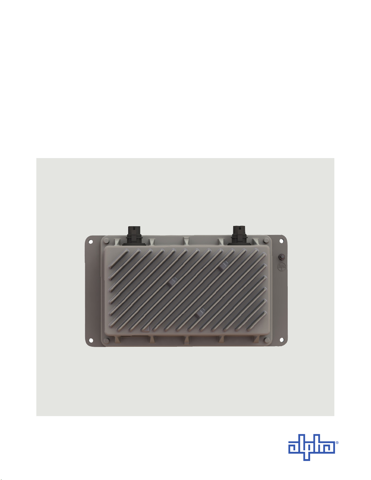
2.2 Introduction ................................................................................................................................ 7
2.3 Part Number............................................................................................................................... 7
2.4 Product Features ....................................................................................................................... 8
3. Product Specications ..........................................................................................................9
4. Pre-installation Requirements.............................................................................................10
4.1 Eective Capacitance .............................................................................................................. 10
4.2 RFT-V Circuits.......................................................................................................................... 10
4.3 Primary Protection ................................................................................................................... 10
4.4 Installation Locations ............................................................................................................... 10
5. Inspection............................................................................................................................11
5.1 Packing Materials......................................................................................................................11
5.2 Check for Damage ....................................................................................................................11
5.3 General Receipt of Shipment....................................................................................................11
6. Installation...........................................................................................................................12
6.1 Safety Precautions................................................................................................................... 12
6.2 Tools Required ......................................................................................................................... 12
6.3 Module Preparation/Mounting.................................................................................................. 12
7. Wiring..................................................................................................................................13
7.1 DC Input and Output/Alarm Connectors .................................................................................. 13
7.2 LPR Cable Kit .......................................................................................................................... 15
8. Initial Start Up .....................................................................................................................17
8.1 Normal Mode of Operation....................................................................................................... 17
8.2 Reverse Polarity Protection ..................................................................................................... 17

0120048-J0 Rev D
4
9. Warranty Statement and Service Information .....................................................................18
9.1 Technical Support .................................................................................................................... 18
9.2 Warranty Statement ................................................................................................................. 18
9.3 Product Warranty ..................................................................................................................... 18
9.4 Battery Warranty ...................................................................................................................... 18
9.5 Warranty Claims....................................................................................................................... 18
9.6 Service Information .................................................................................................................. 18
10. Acronyms and Denitions .................................................................................................19
11. Certication .......................................................................................................................20
List of Figures
Figure 1 — Front View of the LPRxx-150-IP168............................................................................... 7
Figure 2 — Output and Input Connector View ................................................................................ 13
Figure 3 — Detail A, Output/Alarm.................................................................................................. 14
Figure 4 — Detail B, Input............................................................................................................... 14
Figure 5 — DC Input Cable Connector ........................................................................................... 15
Figure 6 — Anderson Power Products (APP) tool (PM100G1)....................................................... 15
Figure 7 — DC Output/Alarm Cable Connector.............................................................................. 16
Figure 8 — Anderson Power Products (APP) tool (PM100G1)....................................................... 16

5
0120048-J0 Rev D
1. Safety
SAVE THESE INSTRUCTIONS: This manual contains important safety instructions that must
be followed during the installation, servicing, and maintenance of the product. Keep it in a safe place. Review the
drawings and illustrations contained in this manual before proceeding. If there are any questions regarding the safe
installation or operation of this product, contact Alpha Technologies or the nearest Alpha representative.
1.1 Safety Symbols
To reduce the risk of injury or death, and to ensure the continued safe operation of this product, the following sym-
bols have been placed throughout this manual. Where these symbols appear, use extra care and attention.
The use of ATTENTION indicates specic regulatory/code requirements that may aect the
placement of equipment and/or installation procedures.
WARNING!
WARNING presents safety information to PREVENT INJURY OR DEATH to personnel.
Warnings are indicated by a shock hazard icon, the word WARNING, and a rule beneath
which the information appears.
WARNING!
You must read and understand the following warnings before installing the enclosure
and its component. Failure to do so could result in personal injury or death.
CAUTION!
CAUTION indicates safety information intended to PREVENT DAMAGE to material or
equipment. Cautions are designated with a yellow warning triangle, the word CAUTION,
and a rule beneath which the information appears.
NOTE:
A NOTE provides additional information to help complete a specic task or procedure.
Notes are designated with a checkmark, the word NOTE, and a rule beneath which the
information appears
HOT!
The use of HOT presents safety information to PREVENT BURNS to the technician or
user.
1.2 General Warnings and Cautions
• Read and follow all instructions included in this manual.
• Only trained personnel are qualified to install or replace this equipment and its components.
• Use proper lifting techniques whenever handling equipment, parts, or batteries.

0120048-J0 Rev D
6
1.3 Electrical Safety
WARNING!
Before working with any live battery or power system, follow these precautions:
a. Remove all metallic jewelry, such as watches, rings, metal rimmed glasses, or necklaces.
b. Wear safety glasses with side shields at all times during the installation.
c. Use OSHA approved insulated hand tools. Do not rest tools on top of batteries.
Lethal voltages are present within the power system. Always assume that an electrical
connection or conductor is energized. Check the circuit with a voltmeter with respect to
the grounded portion of the enclosure (both AC and DC) before performing any installa-
tion or removal procedure.
WARNING!
Hazardous voltages are present at the input of power systems. The DC output from rec-
tiers and batteries, though not dangerous in voltage, has a high short-circuit current
capacity that may cause severe burns and electrical arcing.
• Do not work alone under hazardous conditions.
• A licensed electrician is required to install permanently wired equipment. Input voltages can range up to
240 Vac. Ensure that the utility power is disconnected and locked out before performing any installation or
removal procedure.
• Ensure that no liquids or wet clothes come into contact with internal components.
• Hazardous electrically live parts inside this unit are energized from the batteries even when the AC input
power is disconnected.
• The enclosure which contains the DC or AC power system must remain locked at all times, except when
authorized service personnel are present.
• Always assume electrical connections or conductors are live. Turn off all circuit breakers and double-check
with a voltmeter before performing installation or maintenance.
• Place a warning label on the utility panel to warn emergency personnel that a reserve battery source is pres-
ent which will power the loads in a power outage condition or if the AC disconnect breaker is turned off.
• At high ambient temperature conditions, the internal temperature can be hot so use caution when touching
the equipment.

7
0120048-J0 Rev D
2. Product Overview
2.1 Scope of the Manual
This instruction manual explains the installation and interconnection of Alpha Technologies’ LPR12-150-IP68 and
LPR48-150-IP68 converter system. To aid with installation, frequent reference is made to the drawings located at the
rear of the manual.
2.2 Introduction
The LPRxx-150-IP68 is a compact, sealed, standalone, RFT-V line powering down-converter unit designed for
remote site powering applications using +/- 190Vdc (RFT-V circuit) over twisted copper pairs. The LPRxx-150-IP68
provides a bulk regulated nominal 12 or -48Vdc output from two twisted copper pairs, with maximum power of
150W.
Line Powering Network (a.k.a. Express, Simplex, Remote, Centralized) is a method of distributing energy over an
existing copper network. Multiple twisted-pair copper is used to distribute 100VA limited power sources at ±190Vdc.
The individual, isolated inputs are terminated at a remote end and converted back to a bulk 12Vdc or 48Vdc supply.
Power holdup capabilities are incorporated into the LPRxx-150-IP68 to provide at least 150 millisecond of backup for
a 100 W load. The holdup prevents potential lengthy customer communication outages due to remote node reset-
ting caused by line surges and ensure maximum reliability.
See the Features section for more information. The Specifications Section of this manual, details the electrical rat-
ings.
2.3 Part Number
This product is available to order under the following part numbers:
LPR12-150-IP68 0370421-001
LPR48-150-IP68 0370414-001
Figure 1 — Front View of the LPRxx-150-IP168

0120048-J0 Rev D
8
2.4 Product Features
Output Power
Each of the two isolated converters on each LPRxx-150-IP68 module has a maximum output capacity of 75W (for a
total capacity of 150W per module). The power output is a function of the input voltage into each converter. Proper
network engineering and copper pair sizing is a requirement for meeting the power demand of the load.
Current Limit
The current limiting function provides a primary response to output overload situations.
Input Low Voltage Protection
The converter module is electronically protected from low voltages at the inputs by fault detection circuitry. If the
input to the converter module falls below the lower DC input limit (see Specifications), the module will shut down.
Reverse Polarity Protection
The converter design has incorporated reverse polarity protection from the connection to a power source on the
input. This prevents damage to the converter circuitry if a reverse connection is made.
Module Alarm Relay
The module alarm relay (Form C dry contact) is deenergized (i.e., NO to Com is open) if any or both of the two chan-
nel outputs fail.

9
0120048-J0 Rev D
3. Product Specifications
Electrical
Input voltage: 200 to 380Vdc (+/- 100 to +/- 190Vdc)
Number of Inputs: 2
Input Current per feed: 245mA max
Output voltage: LPR12-150-IP68: 12 to 14Vdc
LPR48-150-IP68: -54 to -56Vdc
Power: up to 150W (the power available from the unit depends on the distance from the up-
converter and wire gauge of the twisted copper pairs)
Output Current: 12.5A (12V)at full rated load of 150W (de-rates with input voltage)
2.74A (48V) at full rated load of 150W (de-rates with input voltage)
Eciency: 86% (12V) at nominal output
89.5% (48V) at nominal output
Regulation: <2% no load to full load
<1% line
Electrical Noise: 100mVRMS to 20MHz (wide band)
<500mVp-p to 20MHz
Hold up Time: >150 millisecond at 100W load
Load Sharing: +/- 10%
Mechanical
Dimensions (HxWxD): millimeters: 70H x 255W x 140D
inches:2.8H x 10.0W x 5.5D
Weight: 1.7 kg (3.7 .lb)
Connections: Requires LPR cable kit with pre-connectorized input and output cable
Environmental
Temperature Operating: -40 to 65˚C (-40 to 149˚F)
Temperature Storage: -40 to 85˚C (-40 to 185˚F)
Environmental Protection: IP68 (immersion in 6ft (2m) of water for 24 hours)
Humidity 5 to 100% RH non-condensing
Altitude: -500 to 2000m (-1640 to 6562ft).
Performance / Features
Alarm Relays: Form C contact
Agency Compliance
Safety:
IEC/CSA/UL 60950-1
Compatible with IEC/CSA/UL 60950-21 (RFT-V circuit)
IEC/CSA/UL 60950-22
Low Voltage Directive 2006/95/EC
EMC:
CFR47 (FCC) Part 15 Class B
EN 300 386 v1.6.1
EMC Directive 2014/30/EC

0120048-J0 Rev D
10
4. Pre-installation Requirements
4.1 Effective Capacitance
At the time of installation, carry out a system assessment to ensure that the effective capacitance of the total system,
including the capacitance from the output of the up-converter (front-end), does not exceed 11μF (Line to Earth) and
40μF (Line to Line).
4.2 RFT-V Circuits
At the time of installation, ensure that the voltage rating of the wiring of the telecommunication network is adequate
for thenormal RFT circuit voltage (+/-200Vdc), together with superimposed transients.
Ensure that the circuits to be connected together are all RFT-V circuits.
4.3 Primary Protection
The LPR Series has built-in surge protection across the input terminals in compliance with the GR-1089-CORE re-
quirement. External primary protection isrecommended for outdoor aerial installation.
4.4 Installation Locations
Allowable installation locations for the LPR converters include the following: outdoors, direct sunlight, and inside or
outside a cabinet.

11
0120048-J0 Rev D
5. Inspection
5.1 Packing Materials
Alpha is committed to providing products and services that meet our customers’ needs and expectations in a sus-
tainable manner, while complying with all relevant regulatory requirements. As such Alpha strives to follow our quality
and environmental objectives from product supply and development through to the packaging for our products.
Rectifiers and batteries are shipped on individual pallets and are packaged according to the manufacturer’s guide-
lines.
Almost all of Alpha’s packaging material is from sustainable resources and/or is recyclable. See the following table
for the material and its environmental codes.
5.1.1 Returns for Service
Save the original shipping container. If the product needs to be returned for service, it should be packaged in its
original shipping container. If the original container is unavailable, make sure that the product is packed with at least
three inches of shock-absorbing material to prevent shipping damage.
Alpha Technologies is not responsible for damage caused by improper packaging of returned products.
5.2 Check for Damage
Before unpacking the product, note any damage to the shipping container. Unpack the product and inspect the
exterior for damage. If any damage is observed, contact the carrier immediately.
Continue the inspection for any internal damage. In the unlikely event of internal damage, inform the carrier and con-
tact Alpha Technologies for advice on the impact of any damage.
5.3 General Receipt of Shipment
The inventory included with your shipment depends on the options you have ordered. The options are clearly
marked on the shipping container labels and bill of materials.
Call Alpha Technologies if you have any questions before you proceed: 1 888 462-7487.
Cardboard Polyethylene
Terephthalate
Low Density
Polyethylene
Polystyrene Steel Aluminum Wood
Packing boxes
Caps
Flexible film
Packaging
Bubble wrap
Shrink wrap
Plastic bags
Foam Strapping on
pallets
Strapping on
pallets
Pallets
Lumber

0120048-J0 Rev D
12
WARNING!
This system is designed to be installed in a restricted access location that is inacces-
sible to the general public.
6. Installation
This chapter is provided for qualified personnel to install the product, which shall be mounted in the most non
extreme environment. The installer should follow all applicable local rules and regulations for electrical and battery
installations; e.g., CSA, UL, CEC, NEC, OSHA, and local fire codes.
6.1 Safety Precautions
Refer to the Safety section near the front of this manual.
6.2 Tools Required
Various insulated tools are essential for the installation.
Use this list as a guide:
• Electric drill with hammer action, 1/2" capacity.
• Various crimping tools and dies to match lugs used in installation.
• Digital voltmeter equipped with test leads.
• Cutters and wire strippers (#14 to #22 AWG) [2.5 to 0.34 mm²].
6.3 Module Preparation/Mounting
For detailed information refer to 0120048-08 drawing at the rear of this manual.
Recommended hardware:
• 4x #10 screws or bolts
• 4x #10 flat narrow washers with 0.75" OD max.
The LPRxx-150-IP68 can be mounted to surfaces with #10 (M5) fastening hardware in four locations. Alpha recom-
mends using flat washers for improved fastening.

13
0120048-J0 Rev D
WARNING!
For safety reasons, ensure the shelf is properly bonded to the enclosure’s ground grid.
Input voltage shall meet UL60950-21 RFT-V requirements. DO NOT CONNECT TO RFT-C
CIRCUITS.
Chassis must be permanently grounded.
-48V return (RTN) shall be earthed.
Telecom cable carrying ±190V, shall be #26 AWG minimum (rated 200V minimum).
Primary over voltage protection must be provided on all input pairs.
Insulation of the outside plant conductors should be rated >90°C (194°F).
Insulation of the wiring inside the enclosed equipment cabinets should be rated 105°C
(221°F) minimum. Cables must be dressed to avoid damage to the conductors.
7. Wiring
7.1 DC Input and Output/Alarm Connectors
SCALE:
REV
SHEET
SIZE
DWG NO.
TITLE:
OF
C
1:2
B
1 1
0120048_57-08
OUTLINE/CONNECTION
DRAWING, LPR-IP68
THESE DESIGNS AND SPECIFICATIONS ARE
CONFIDENTIAL, REMAIN THE PROPERTY OF
ALPHA TECHNOLOGIES LTD., AND SHALL NOT BE
COPIED OR USED WITHOUT ITS WRITTEN CONSENT
© ALPHA TECHNOLOGIES LTD
CHECKED
DRAWN
DATE
APPROVALS
KLAU
Feb-20-15
Feb-20-15
ZL
THIRD ANGLE PROJECTION
UNLESS OTHERWISE SPECIFIED
DIM ARE IN MM
INTERPRET DIM AND TOL PER
ASME Y14.5M-1994
X
X.X
X.XX
ANGULAR:
1
1
0.5
0.25
140.50 124.0 4.88
240.0 9.45
4X
5.5 0.22
THRU
102.0 4.0
MINIUMUM DISTANCE
TO ADJACENT WALL FOR
CABLE BEND RADIUS
63.0 2.48
192.0 7.56
70.0 2.76
255.0 10.04
AB
GROUND STUD
FOR 4mm OR #10
RING LUG
31.5 1.24
DETAIL A
SCALE: 1 : 1
P5
P4
P3
P2
DETAIL B
SCALE: 1 : 1
P2 P5
P4
P3
REVISIONS
LTR
DESCRIPTION
DWN
DATE
CHK
A
INITIAL RELEASE
ZL
Feb-20-15
KLAU
B
UPDATED FOR NEW HOUSING
ZL
May-26-15
KLAU
C
CABLES REPLACED WITH CONNECTERS
ZL
Apr-14-16
TZ
PIN #
CIRCUIT
DESIGNATION
INPUT A
5
+190V_ChA
4
-190V_ChA
INPUT B
2
+190V_ChB
3
-190V_ChB
PIN #
CIRCUIT
DESIGNATION
(48V)
CIRCUIT
DESIGNATION
(12V)
OUTPUT
2
48V_RTN
GND
3
-48V
+12V
ALARM
4
K1_COMMON
5
K1_COMMON
A
B
C
D
E
123
4
5
D
A
C
E
B
13
542
DO NOT SCALE DRAWING
Figure 2 — Output and Input Connector View
CAUTION!
This equipment is intended to be used in outdoor environments.
Load connections should be made in close proximity to the power output.

0120048-J0 Rev D
14
Figure 3 — Detail A, Output/Alarm
Figure 4 — Detail B, Input
SCALE:
REV
SHEET
SIZE
DWG NO.
TITLE:
OF
E
1:2
B
1 1
0120048-08
OUTLINE/CONNECTION
DRAWING, LPR48-150-IP68
THESE DESIGNS AND SPECIFICATIONS ARE
CONFIDENTIAL, REMAIN THE PROPERTY OF
ALPHA TECHNOLOGIES LTD., AND SHALL NOT BE
COPIED OR USED WITHOUT ITS WRITTEN CONSENT
© ALPHA TECHNOLOGIES LTD
CHECKED
DRAWN
DATE
APPROVALS
KLAU
Feb-20-15
Feb-20-15
ZL
THIRD ANGLE PROJECTION
UNLESS OTHERWISE SPECIFIED
DIM ARE IN MM
INTERPRET DIM AND TOL PER
ASME Y14.5M-1994
X
X.X
X.XX
ANGULAR:
1
1
0.5
0.25
140.50 124.0 4.88
240.0 9.45
4X
5.5 0.22
THRU
102.0 4.0
MINIMUM DISTANCE
TO ADJACENT WALL FOR
CABLE BEND RADIUS
63.0 2.48
192.0 7.56
70.0 2.76
255.0 10.04
AB
GROUND STUD
FOR 4mm OR #10
RING LUG
31.5 1.24
DETAIL A
SCALE: 1 : 1
P5
P4
P3
P2
E
DETAIL B
SCALE: 1 : 1
P2 P5
P4
P3
CONNECTOR CAPS REMOVED
FOR CLARITY
E
REVISIONS
LTR
DESCRIPTION
DWN
DATE
CHK
A
INITIAL RELEASE
ZL
Feb-20-15
KLAU
B
UPDATED FOR NEW HOUSING
ZL
May-26-15
KLAU
C
CABLES REPLACED WITH CONNECTORS
ZL
Apr-14-16
TZ
D
ADDED CONNECTOR CAPS
ZL
May-30-16
KLAU
E
CORRECTED POLARITY ON OUTPUT
ZL
Aug-08-18
PA
PIN #
CIRCUIT
DESIGNATION
INPUT A
5
+190V_ChA
4
-190V_ChA
INPUT B
2
+190V_ChB
3
-190V_ChB
PIN #
CIRCUIT
DESIGNATION
OUTPUT
2
-48V
3
48V_RTN
ALARM
4
K1_COMMON
5
K1_NO
A
B
C
D
E
123
4
5
D
A
C
E
B
13
542
DO NOT SCALE DRAWING
SCALE:
REV
SHEET
SIZE
DWG NO.
TITLE:
OF
C
1:2
B
1 1
0120048_57-08
OUTLINE/CONNECTION
DRAWING, LPR-IP68
THESE DESIGNS AND SPECIFICATIONS ARE
CONFIDENTIAL, REMAIN THE PROPERTY OF
ALPHA TECHNOLOGIES LTD., AND SHALL NOT BE
COPIED OR USED WITHOUT ITS WRITTEN CONSENT
© ALPHA TECHNOLOGIES LTD
CHECKED
DRAWN
DATE
APPROVALS
KLAU
Feb-20-15
Feb-20-15
ZL
THIRD ANGLE PROJECTION
UNLESS OTHERWISE SPECIFIED
DIM ARE IN MM
INTERPRET DIM AND TOL PER
ASME Y14.5M-1994
X
X.X
X.XX
ANGULAR:
1
1
0.5
0.25
140.50 124.0 4.88
240.0 9.45
4X
5.5 0.22
THRU
102.0 4.0
MINIUMUM DISTANCE
TO ADJACENT WALL FOR
CABLE BEND RADIUS
63.0 2.48
192.0 7.56
70.0 2.76
255.0 10.04
AB
GROUND STUD
FOR 4mm OR #10
RING LUG
31.5 1.24
DETAIL A
SCALE: 1 : 1
P5
P4
P3
P2
DETAIL B
SCALE: 1 : 1
P2 P5
P4
P3
REVISIONS
LTR
DESCRIPTION
DWN
DATE
CHK
A
INITIAL RELEASE
ZL
Feb-20-15
KLAU
B
UPDATED FOR NEW HOUSING
ZL
May-26-15
KLAU
C
CABLES REPLACED WITH CONNECTERS
ZL
Apr-14-16
TZ
PIN #
CIRCUIT
DESIGNATION
INPUT A
5
+190V_ChA
4
-190V_ChA
INPUT B
2
+190V_ChB
3
-190V_ChB
PIN #
CIRCUIT
DESIGNATION
(48V)
CIRCUIT
DESIGNATION
(12V)
OUTPUT
2
48V_RTN
GND
3
-48V
+12V
ALARM
4
K1_COMMON
5
K1_COMMON
A
B
C
D
E
123
4
5
D
A
C
E
B
13
542
DO NOT SCALE DRAWING
PIN #
CIRCUIT
DESIGNATION
(48V)
CIRCUIT
DESIGNATION
(12V)
OUTPUT 2 -48V GND
3 48V_RTN +12V
ALARM 4 K1_COMMON
5 K1_NO
PIN #
CIRCUIT
DESIGNATION
(48V)
INPUT A 5 +190V_ChA
4 -190V_ChA
INPUT B 2 +190V_ChB
3 -190V_ChB

15
0120048-J0 Rev D
7.2 LPR Cable Kit
The LPR cable kit included provides a set of two, 2m (6ft) long cables each with one cut cable end, and one end
pre-terminated with an LPR mating connector. The kit contains:
• Input cable
• Output/Alarm cable
7. 2 .1 DC Input
DC Input cable use: 4x #22AWG. Use the following mating cables for DC input connections. Crimp with Anderson
Power Products (APP) tool (PM100G1).
Figure 6 — Anderson Power Products (APP) tool (PM100G1).
Input Wire Color Circuit Designation
Input A Blue/White +190V_ChA
Blue -190V_ChA
Input B Orange -190V_ChB
Orange/White +190V_ChB
Figure 5 — DC Input Cable Connector
Description Alpha PN Manufacturer PN
4 Heavy duty Power Connectors, 5 Positions, MINI,
22A, IP68, UV and Flame Resistant Plastic
5450299 APP SK1-021M05
3 Sealing Gland, 5 Postilions, IP68, UV and Flame
Resistant Plastic
5450300 APP PS1T24-11X
2 Heavy Duty Power Connector Socket, 24-20AWG,
Gold Plated
5380190 APP PM16S2024S32
1 Cable, 4 Conductors, 22AWG, Solid, Shielded,
Direct Burial (Qty - 6ft)
8580054 Superior Essex 04-052-84

0120048-J0 Rev D
16
Description Alpha PN Manufacturer PN
4 Heavy duty Power Connectors, 5 Positions, MINI,
22A, IP68, UV and Flame Resistant Plastic
5450299 APP SK1-019M05
3 Sealing Gland, 5 Postilions, IP68, UV and Flame
Resistant Plastic
5450300 APP PS1T24-11x
2 Heavy Duty Power Connector Pin, 16-14AWG,
Gold Plated
5380178 APP PM16P1416S30
1 Portable Cord Cable, 4 Conductors, 14AWG,
SJ00W Type, Standard, 300V (Qty - 6ft)
8580053 General Cable HF343 or
equivalent
Figure 7 — DC Output/Alarm Cable Connector
7.2.2 DC Output/Alarm
DC Output/Alarm cable use: 4x #14AWG. Use the following mating cable assembly for DC output connections.
Crimp with Anderson Power Products (APP) tool (PM1000G1).
Figure 8 — Anderson Power Products (APP) tool (PM100G1).
Output Wire Color Circuit Designation
LPR48-150-IP68 LPR12-150-IP68
Output Black -48V GND
Red 48V_RTN +12V
Alarm Green K1_COMMON
White K1_NO

17
0120048-J0 Rev D
8. Initial Start Up
1. Remove customer-supplied 5-pin protectors (if available) from power-pairs termination block and disconnect the
output –48V cable.
2. Verify by both measurement and observation that the chassis of the system is bonded to ground.
3. Connect module input cable to the host system
4. Complete the input circuits by plugging in the 5-pin protectors.
5. Measure the output voltage to be <14Vdc for LPR12-150 or <56Vdc for LPR48-150 and reconnect the output
cable.
8.1 Normal Mode of Operation
Normal operation of the converter system will be indicated by the presence of voltage on the converter output
cables.
8.2 Reverse Polarity Protection
The converter will not be damaged and will operate if an input connection is made in reverse.

0120048-J0 Rev D
18
9. Warranty Statement and Service Information
9.1 Technical Support
In Canada and the USA, call toll free 1-888-462-7487.
Customers outside Canada and the USA, call +1-604-436-5547.
9.2 Warranty Statement
For full information details review Alpha's online Warranty Statement at www.alpha.ca/support.
9.3 Product Warranty
Alpha warrants that for a period of two (2) years from the date of shipment its products shall be free from defects
under normal authorized use consistent with the product specifications and Alpha’s instructions, the terms of the
manual will take precedence.
The warranty provides for repairing, replacing or issuing credit (at Alpha’s discretion) for any equipment manufac-
tured by it and returned by the customer to the factory or other authorized location during the warranty period.
There are limitations to this warranty coverage. The warranty does not provide to the customer or other parties any
remedies other than the above. It does not provide coverage for any loss of profits, loss of use, costs for removal
or installation of defective equipment, damages or consequential damages based upon equipment failure during or
after the warranty period. No other obligations are expressed or implied. Warranty also does not cover damage or
equipment failure due to cause(s) external to the unit including, but not limited to, environmental conditions, water
damage, power surges or any other external influence.
The customer is responsible for all shipping and handling charges. Where products are covered under warranty
Alpha will pay the cost of shipping the repaired or replacement unit back to the customer.
9.4 Battery Warranty
Note that battery warranty terms and conditions vary by battery and by intended use. Contact your Alpha sales
representative or the Technical Support team at the above number to understand your entitlements under Battery
Warranty.
9.5 Warranty Claims
Any claim under this Limited Warranty must be made in writing to Alpha BEFORE sending material back. Alpha will
provide Product return instructions upon approval of return request. A Service Repair Order (SRO) and / or Return
Authorization (RA) number will be issued ensuring that your service needs are handled promptly and efficiently.
Claims must be made online at: www.alpha.ca.
9.6 Service Information
For a list of international service centers, refer to the Alpha website: www.alpha.ca
Table of contents
Other Alpha Technologies Media Converter manuals

Alpha Technologies
Alpha Technologies CXDF24482KW User manual

Alpha Technologies
Alpha Technologies CXPS 24-48-i User manual

Alpha Technologies
Alpha Technologies CSM46 User manual

Alpha Technologies
Alpha Technologies LPR48-300 User manual

Alpha Technologies
Alpha Technologies CXDF 48-24/2kW User manual

Alpha Technologies
Alpha Technologies CXDF 24-48/2kW User manual

Alpha Technologies
Alpha Technologies CXDF 48-24Vdc/2kW User manual