manuals.online logo
Brands
  1. Home
  2. •
  3. Brands
  4. •
  5. Alpha
  6. •
  7. Circuit Breaker
  8. •
  9. Alpha XM2-300HP User manual

Alpha XM2-300HP User manual

DPM Hardware Installation and Quick Start Guide
Configuring the network prior to installation is recommended to allow the
transponder communication to be verified while the technician is on-site
eliminating the need for a second visit if there are any problems.
HardwareInstallation Procedure
1. Install the DPM.
a. Turn the XM2-300HP battery circuit breaker off.
b. Disconnect the battery from the front of the XM2-300HP.
c. Disconnect the temperature sensor.
d. Loosen the three inverter module thumbscrews, and slide the inverter
module out of the power supply.
e. Remove the existing communications panel from the inverter module.
f. Place the transponder on the sheet metal, inserting the RF connector
through the hole in the angled flange. Secure the circuit board to the panel
with the two supplied Phillips head screws.
g. Insert the 18 pin header (Alpha p/n: 540-492-19) into the 18 hole
connector on the backside of the DPM.
h. Press the DPM into the Inverter Module, aligning the 18-pin header
correctly with the Inverter Module connector (Figures 4-6).
i. Tighten the two captive screws to secure the assembly to the inverter
module.
j. Reinstall the inverter module, and tighten the three thumbscrews.
k. Connect the environmental controller and/or LAP, and tamper switch (if
present).
l. Reconnect the battery, and temperature sensor.
m. Turn the battery circuit breaker back on.
Provision the RF MAC Address
The RF (modem) MAC Address is printed on barcode labels on the side
of the DPM (Fig.3), as well as on the packing slip.
• Provision via the proper DOCSIS®configuration file.
For units in service, backup battery power will not be available during
the procedure.
CAUTION!
Fig. 2, Smart Display
Fig. 3, Captive Screw /MAC Address Label
location
Fig. 6, Connecting the DPM
to the Inverter Module
Fig. 5, Inverter Module connector
Verify the battery breaker remains in the OFF position during
installation procedure.
CAUTION!
Fig. 4, 18 Pin Header
(Alpha p/n: 540-492-19)
Fig. 1, Front view with callouts
6
5
8
7
9
2
1
4
3
2
1
4
3
6
5
8
7
9
ALM/RDY LED
Downstream Activity LED
Rx/Tx RF Power Status LED
LEDs for COM activity
Reset (RST) Button
Environmental (ENV) Control connector
Tamper Switch Connection
Ethernet (ETH) port
RF Connection
Battery Input
10
10
Total Power Solutions
For contact information visit www.alpha.com
The Alpha Group >
Alpha Technologies reserves the right to make changes to the products and information contained in this document without notice.
Copyright © 2010 Alpha Technologies. All Rights Reserved.Alpha®is a registered trademark ofAlpha Technologies.
North America Europe, Middle East & Africa Asia Pacific Latin & South America
USA Cyprus Germany Lithuania P.R. China Contact USA office
Tel: +1 360 647 2360 Tel: +357 25 375 675 Tel: +49 9122 79889 0 Tel: +370 5 210 5291 Tel: +852 2736 8663
Fax: +1 360 671 4936 Fax: + 357 52 359 595 Fax: +49 9122 79889 21 Fax: +370 5 210 5292 Fax: +852 2199 7988
Canada Russia United Kingdom
Tel: +1 604 430 1476 Tel: +7 495 925 9844 Tel: +44 1279 501110
Fax: +1 604 430 8908 Fax: +7 495 916 1349 Fax: +44 1279 659870
745-877-B2-001 Rev.A(12/10)
3. Initial Start-up and Test.
Plug the power supply into the AC outlet and
turn on the battery switch (XM2-HP units
perform a 10-second self test to check the
batteries).
The DPM LEDs blink three times and the
RDY light begins blinking on and off.
Verify the DS and REG LEDs are on solid.
This verifies the DPM has registered an IP
address on the public network.
Verify the RF LED is solid Green, indicating
Downstream RF Power is between
±12dBmV.
Verify no alarms are active.
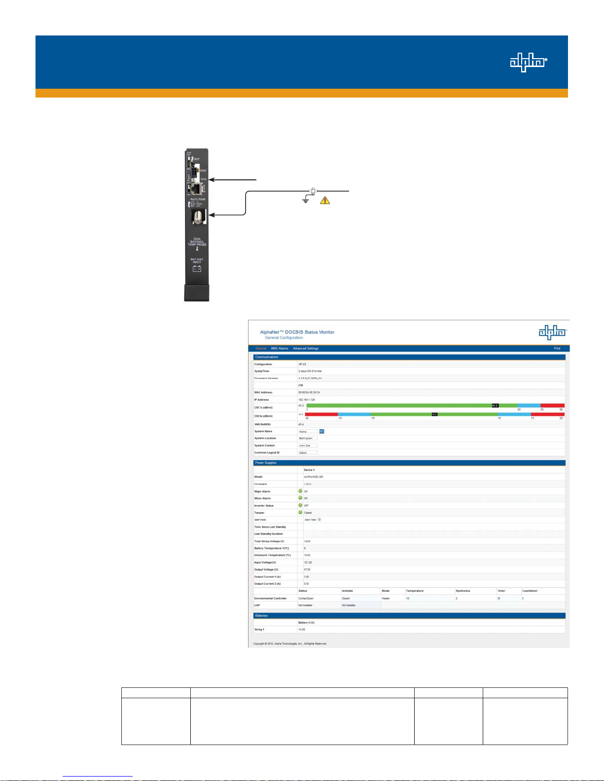
4. Test the Connection.
Connectivity may be verified via the COMMS
Menu of the XM2-HP smart display (Fig.
1). You may also test the connection using
a computer and a standard ethernet cable.
Connect the computer to the ethernet port
on the transponder, launch an Internet
browser (e.g. Internet Explorer), and
use 192.168.100.1 in the address field.
Connectivity, power levels, and security
information will be displayed. The System
Name, System Location, System Contact,
and Common Logical ID may be edited on
this page; when prompted for a User Name
and Password, use "Alpha" and "AlphaGet".
Fig. 8, Configuration Page
RF Cable to Headend
Required
Grounded Surge Protector
(Alpha P/N 162-028-10 or equivalent)
Tamper switch
2. Connect the RF drop and make front panel connections (as shown in Fig. 7).
The DOCSIS specification for downstream power level is ± 15dBmV. However, for optimal performance, set the level as close to
0dBmV as possible.
Fig. 7, Wiring Diagram

Other manuals for XM2-300HP

1

This manual suits for next models

1

Popular Circuit Breaker manuals by other brands

ABB SACE Emax 2 manual

ABB

ABB SACE Emax 2 manual

TERASAKI TemBreak 2 instruction manual

TERASAKI

TERASAKI TemBreak 2 instruction manual

Block ECONOMY SMART PC-FU/DC24 manual

Block

Block ECONOMY SMART PC-FU/DC24 manual

Eaton Bussmann Series installation manual

Eaton

Eaton Bussmann Series installation manual

CHINT RT36 Mounting instructions

CHINT

CHINT RT36 Mounting instructions

Allis-Chalmers LA-600 Instruction book

Allis-Chalmers

Allis-Chalmers LA-600 Instruction book

Siemens Energy SB ICCB Installing

Siemens Energy

Siemens Energy SB ICCB Installing

Block ECONOMY SMART manual

Block

Block ECONOMY SMART manual

Siemens 3VL7710 6 Series operating instructions

Siemens

Siemens 3VL7710 6 Series operating instructions

ABB AF40 operating instructions

ABB

ABB AF40 operating instructions

Gewiss MSX manual

Gewiss

Gewiss MSX manual

Siemens Sentron WL operating instructions

Siemens

Siemens Sentron WL operating instructions

Siemens 3AH47 series operating instructions

Siemens

Siemens 3AH47 series operating instructions

Eaton QSA200N Series Instruction leaflet

Eaton

Eaton QSA200N Series Instruction leaflet

GE Spectra Series AMCB6FGB installation instructions

GE

GE Spectra Series AMCB6FGB installation instructions

Siemens 3VA10-ED Series operating instructions

Siemens

Siemens 3VA10-ED Series operating instructions

Eaton FBSmV Instruction leaflet

Eaton

Eaton FBSmV Instruction leaflet

ABB OHB Installation, service and maintenance

ABB

ABB OHB Installation, service and maintenance

manuals.online logo
manuals.online logoBrands
  • About & Mission
  • Contact us
  • Privacy Policy
  • Terms and Conditions

Copyright 2025 Manuals.Online. All Rights Reserved.