Alpha 5i User manual

Alpha 5i RTK User Guide
Alpha 5i GNSS RECEIVER QUICK GUIDE
Keep this manual safe for reference and future maintenance
Alpha Surveying and mapping
5
i
1、 GNSS Receiver
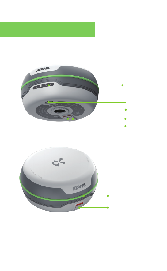
1.1 Alpha 5i Description
Indicator Lights
Power On/Off
)C-epyt(stroP gnigrahC
TNC Interface
Height-measurement Line
5
iSIM Card Slot

1.2 Indicator Light
Indicators color Description
Green light on: power 30%-100%
Green light flashing: power 10%-30%
Red light flashing:power<10%
Red light on:charging
Light off:no stars found
Red light flashing:few stars found
without positioning
Green light flashing: effective
positioning but don't get fixed
Green light on: fixed
Red light on:GNSS mainboard abnormal
Green light flashing: data transmission
Red light flashing: recording static
Red and green lights flash alternately :
record static and transmit data
green&red
green&red
green&red
Satellite
Data link
Power
Bluetooth
blue
Light off: no connection
Light on: being connected
Flashing: being connected and
downloading differential data
1.3 Self-test Function
The self-test is used to examine whether each module of the
receiver is working healthily. When the instrument is working
abnormally, you can use the self-test function to test the receiver.

2.1 Red Positioning Button
a.Turn on the DiMap: You can directly turn on the DiMap by
pressing the red button when the controller is powered on;
b.Measuring: When the DiMap is in the survey or stakeout
interface, press the red button to collect and store the data.(
1st press for gathering data, 2nd press for confirming the
storage coordinates.)
2、 Alpha Bi Controller
Operating instruction:
Two short press plus a long press until a long beep sound is heard,
the instrument will begin the self-test process. If there is nothing
wrong with the machine, there will be two short beep as a
reminder, otherwise, the warning alarm will sound for a longer
period of time.

2.2 Dat Button
a.Show point database. The Dat button is connected to the
point database when doing survey or stakeout work. The Dat
button coordinated with the red positioning button makes
possible a fast and direct interaction between measuring and
stakeout work.
b.Open the output folder. Press the Dat button can get quick
access to the data output folder once the user logs out the
DiMap.
2.3 Fn Button
The Fn button is used to switch the working mode of the key
2,4,6,8: Direction control mode / Digital mode.
When the Fn button is activated, there will be a start prompt at
the top of the controller.
The following instructions are easy-to-follow tips for new surveyors.
For detailed guidance,please read the user manuals. (Note:The
manuals can be downloaded on the official website:alpha-survey-
ing.com)
(1) Set up the base.
(2) Open the controller and DiMap, connect them to the base station
in a new project and set the parameters of the coordinate system
and base station for sending differential data.
(3) Connect the controller to the rover and prepare it for receiving
differential signals from the base and getting the fixed solution.
(4) Move the rover to a certain place in the measurement area to find
out the original coordinates of the place. Calculate and apply the
transfer parameters.
3.1 General Working Process Of Base & Rover:
3、 Guide For Outdoor Surveying
3.2 Detailed operation instructions of RTK:
Set up the base,and install the UHF antenna when using the radio
mode. Press the power button to turn on the receiver, and wait for
the base to target the satellite.
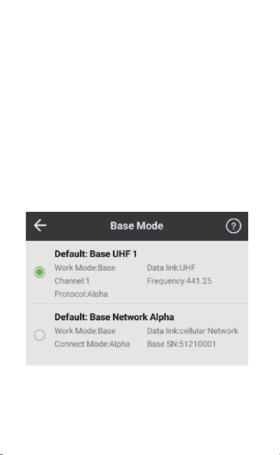
When the controller is connected to the reference station, click
[Device] - [Base Mode] to select the configuration set required in the
measurement work.
3.2.1 Set up the base
(5) Go to another known point to check whether the coordinates are
right after coordinate transformation.
(6) Start the work.
*If the start-up coordinate or the position of the base station change,
you need to perform a maker point calibration process.
(7) Finish the work and export the data file as required.
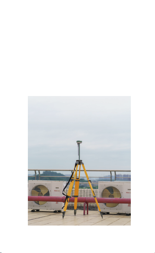
*E.g. Base station set at the top of a building
Requirements of the place you set up the base:
a. Cut-off angle larger than 15 degrees; Open area
without large obstructions.
b. No electromagnetic interference(No microwave
stations, radar stations, or cell phone tower within
200 meters; And no power lines within 50 meters.)
c. Base station should be set up in higher places. There
should be no large obstructions between the base
and the rover or the differential data transmission
distance would be shorter.
*Normally, it is recommended to set up the base stations in open
areas or on the top of high buildings.

Open the DiMap, select [Project]-[Project management]-[New ] and
then name the new project;
Select the coordinate system in the“Preset coordinate system” to
confirm the new project in the new interface.
3.2.2 Create A New Project
Click the positioning button to get the local central meridian
in the Projection interface of the Coordinate system setting.
Then go back and click [Confirm] to keep the settings.
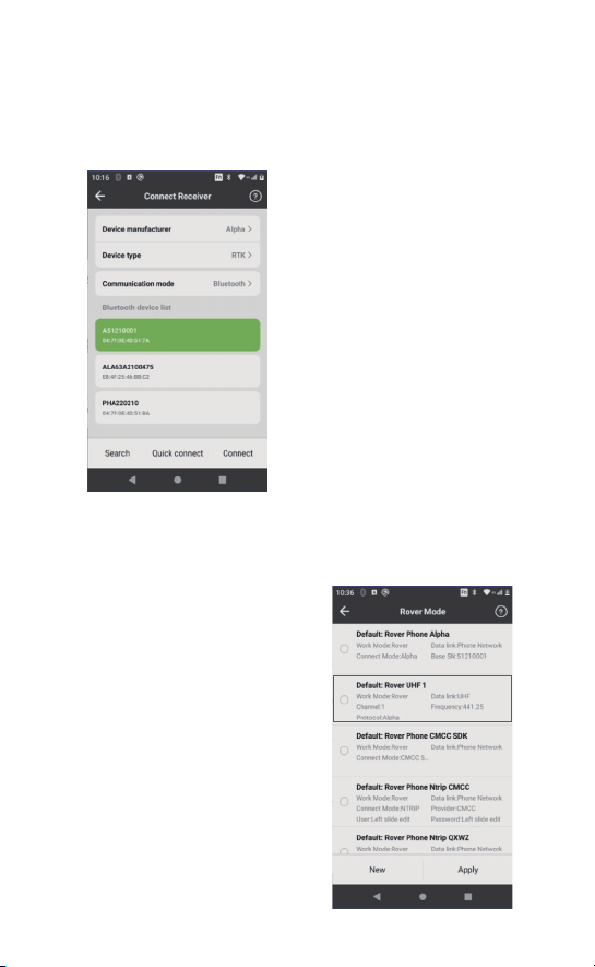
Click[Device]-[Connect Receiver], then search for correspond-
ing serial number to connect the receiver.
①Click [Search] on the bottom
left.
② Choose the corresponding
Alpha device.
③ Click[Connect] to connect the
instrument (bottom right)
(If there is only one Alpha device
nearby, click [Quick connect] on
the middle and the controller will
automatically search and connect
the receiver)
3.2.3 Connection Between Controller And Receiver
3.2.4 Setting Rover Mode
After bluetooth connectivity, click [Device]- [Rover Mode]. The
settings are as follows according to the datalink mode:
【Built-in Radio】 In this mode,
the radio antenna needs to be
inserted, click [Rover
Mode]-[Default:Rover UHF 1],
Click [ Apply] to open the
built-in radio. After setting,
the data link indicator light on
the recriver flashes once per
second, indicates that
differential data is received
normally.
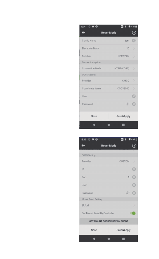
【Network of the instrument】
The mode is connected to
the Internet by the network
of RTK. Open the rover mode
interface, click[New] to
create a new config set. As
for the data link, select the
NETWORK,connection mode
As for the CORS setting,
”motsuc“ esoohc redivorp -
type the right IP address and
ports, username and
password first and then click
[GET MOUNT COORDINATE
BY PHONE] to connect to
the network. Pick the correct
mount point and click
[Save&Apply] to begin
using the network. Wait for
the initialization process of
the rover. The datalink light
on the receiver is green and
flashes once per second,
indicating that the receiver is
able to receive differential
Table of contents
Other Alpha Receiver manuals


