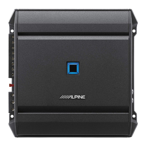
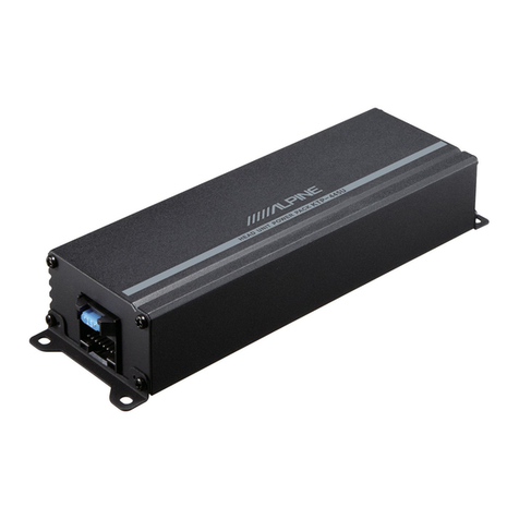
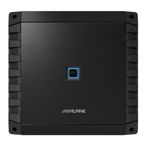
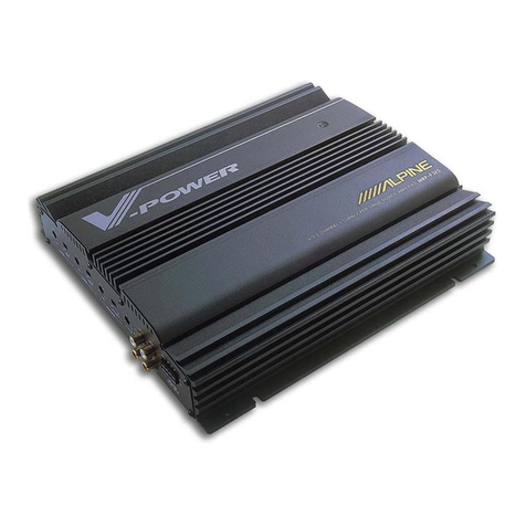
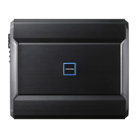
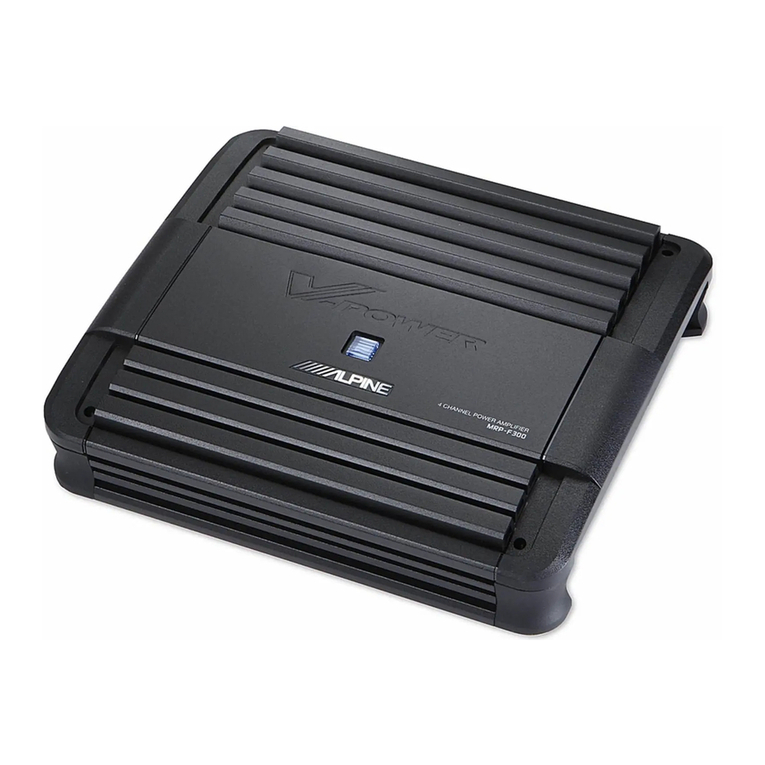
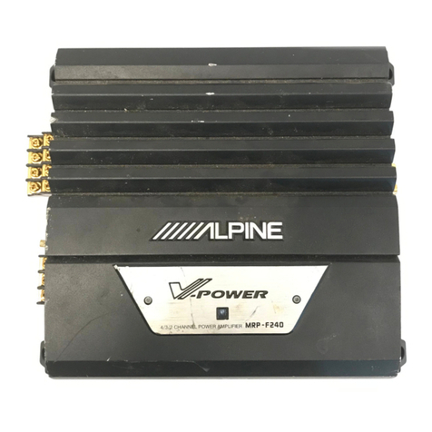
Alpine 35278 User manual

OWNER’S
MANUAL/BEDIENUNGSANLEITUNG/
MANUEL
DU
PROPRIETAIRE/MANUALE
DEL
PROPRIETARIO/
MANUAL
DEL
PROPIETARIO/BRUKSANVISNING
35278
4/3/2
Channel
Power
Amplifier

SYSTEM
CHARTS/SYSTEMAUFBAU/DIAGRAMMES
DU
SYSTEME/DISPOSIZIONI
DEL
SISTEMA/
DIAGRAMAS
DEL
SISTEMA/SYSTEM-OVERSIKT
Figg
VIADD.
4:
seis
sccceccsssceetcacesdeosstieces
cecaneestnedbectieccbeotsasocne’
SWITCHES
AND
TERMINALS/SCHALTER
UND
ANSCHLUSSE/COMMUTATEURS
ET
BORNES/INTERRUTTORI
E
TERMINALI/INTERRUPTORES
Y
TERMINALES/OMKOPPLARE
OCH
ANSLUTNINGAR
Fig.
QVADD.
2
.ccccsssccccsssesosssssssssccssscssessssssossnsssnssnnesesneessee
INSTALLATION/EINBAU/INSTALLATION/INSTALLAZIONE/INSTALACION/AINSTALLATION
@
Fig.
3/Abb.
3
CONNECTIONS/ANSCHLUSSE/CONNEXIONS/COLLEGAMENTI/CONEXIONES/ANSLUTNINGAR
"ENGLISH"
INTRODUCTION
woecsccsccsssesssssccsssccsseesssseccssussssssesssvesssecssesenate
7
FEATURES
i.
schertccciesssocste
cous
htsederevuitéctusacsasteorsuvssnvaliorbeanits
8,9
SWITCHES
AND
TERMINALS
..
..10
PRECAUTIONS
o..cccccssecssseccssccssscesssececessecesnessesesesnereseseceeses
10
CONNECTIONS
wel
-13
TYPICAL
SYSTEM
CONNECTIONS
14-18
INSTALLATION.
csss-iscssuvccusctiaccccnssevassosurseodas
thevasessncensvenulses
19
SWITCH
SETTINGS
20-22
SPECIFICATIONS
....cccecscesscsccscssccsssesssnssssssvesssessesseeesteseneees
23
"DEUTSCH"
EINFUHRUNG
MERKMALE
SCHALTER
UND
ANSCHLUSSE
......scsccscsssossssccssecssscssssssssessrenssesessesseesetsssenuee
27
VORSICHTSMASSNAHMEN
.....cceccssecsscssstsssecsstesseeseeessees
27
ANSCHLUSSE
uu...
.secsesesecsseessees
28-30
TYPISCHE
SYSTEMANSCHLUSSE
31—35
EINBAU
iscczcosdecscectsecdescscedccctsotcetsuceatetecscctassssatiataniensitooveel
36
SCHALTER-EINSTELLUNG
...
37-39
TECHNISCHE
DATEN
..eeccccssesssecsseeccstessecssecsssrsssressrecsneneees
40
"FRANCAIS"
INTRODUCTION
...ccsccssscsssssssccssesssscsssssecsssecsssvestssecsnseesseees
CARACTERISTIQUES
COMMUTATEURS
ET
BORNES
.......cccsscccesssecsseesesseeanes
44
PRECAUTIONS
CONNEXIONS
CONNEXIONS
TYPIQUES
DU
SYSTEME.......
INSTALLATION
REGLAGE
DES
COMMUTATEURS
.
SPECIFICATIONS
eandegs
desesssstwivcustossiscbesnstcceszteoedecsdacesdetesasessascsastectnievedersuqacesssueaacuatte
6
ecitenadoveunenesenazastea
sdgastnnescsuscssssssusasvagyighaseetcovete
locdbondbesedaghstsecsbssnedest
6
"ITALIANO"
INTRODUZIONE
oie.
saascr
sea
cteycnsccyensasvinatageateasbeagdescnesseneeeeedes
58
CARATTERISTICHE
............
59,
60
INTERRUTTORI
E
TERMINAL]
61
PRECAUZIONI
......ceeseeeseseeee
61
COLLEGAMENT
......eeeeeecsceeeeees
62
—
64
SISTEMI
TIPICI
DI
COLLEGAMENTO
65
—
69
INSTALLAZIONE
ooo
ese
eeeseeseesestenesnsncereessesesneseensseseeseees
70
REGOLAZIONE
DEGLI
INTERRUT
CORD!
soc:
cccsscseccscssscsscaiscecvanisvenstvcescssesusivenst
71-73
SPECIPICAZIONU
...c.:occcecessecccosccecseschiaccdacnedendeceuapeadsnecucsdenen
74
"ESPANOL"
INTERRUPTORES
Y
TERMINALES
..
PRECAUCIONES.
.......scscssccssssssssesseessesssecscssesssecssnsessuseseases
78
CONEXIONES
.......csecsssccsssssssscssscsanscovsessscnsesoeesouecnasers
79-81
CONEXIONES
TIPICAS
DEL
SISTEMA
o...cscsssssssesssscesssessecsssecsssccassesssensesnscessees
82-86
INSTALAGION
ic.
cscSucssavceclvssesssusssnsaugcokvavegetaussemmeasanuiesn’
87
AJUSTE
DE
INTERRUPTORES......
..88
-
90
ESPECIFICACIONES
.......cccscsssssssssesssessscecsccssssnsesseeesseessees
91
"SVENSKA"
INTRODUKTION
.o...cccscscessscesssesseecceseesssssseessessneeseceseeesssensess
92
EGENSKAPER
OMKOPPLARE
OCH
ANSLUTNINGAR
.....csssssccessessssteesees
95
FORSIKTIGHETSATGARDER
.....ccccssssscssecsssccssesssreesesneess
95
ANSLUTNINGAR
7
TYPISKA
SYSTEMANSLUTNINGAR
.....csssccseessseseese
99
-
103
INSTALLATION
22cccscccicosdeccecocsbuscusctosessateatilocec’cesassaasvetbane
OMKOPPLARPOSITIONER
.
SPECIFIKATIONER
@
CHARACTERISTIC
CURVES/CHARAKTERISTISCHE
ENTZERRERKURVEN/COURBES
CARACTERISTIQUES/
CURVE
CARATTERISTICHE/CURVAS
CARACTERISTICAS/FREKVENSKURVOR
Fig.
1/Abb.
1

®
Ground
Lead
<>
@
Chassis
@
Holes
Fig.
2/Abb.
2
CONNECTIONS
SSE
Vesey
Oe
cO
eee
_
CONEXIONES/ANSLUTNINGAR.
|
@
RCA
input
Jacks
@
Speaker
Output
Terminals
@
Speaker
Input
Leads
lal
8
©
®
(white)
MU ||
Front
;
Lett
Speaker
\©
®
(White/Black)
9
C
©
(Gray)
Front
Right
Speaker
o®
(Gray/Black)
@
Battery
Lead
(Yellow)
care
:
©
Remote
Turn-On
Lead
(Blue/White)
@
@®
{Green)
=
Heat
e®@
(Green/Black)
wan
Left
Speaker
®
©
B
(violet)
Rear
Right
Speaker
\©
©
(violevBlack)
Fig.
3/Abb.
3

At
Alpine,
Sonic
Excellence
is
a
goal
we
consider
most
important.
Your
purchase
of
this
component
has
told
us
you
feel
the
same.
We
take
great
pride
in
the
long
tradition
of
excellence
in
sound
quality
and
reliability
that
the
Alpine
name
represents.
Now
as
a
part
of
that
tradition,
we
welcome
you
to
the
growing
number
of
discerning
audiophiles
who
own
Alpine
products.
This
manual
has
been
prepared
to
help
you
maximize
your
enjoyment
of
the
outstanding
performance
&
features
of
your
new
Alpine
3527S
4/3/2
Channel
Power
Amplifier.
This
power
amplifier
incorporates
many
advanced
technical
&
perform-
ance
features.
To
realize
the
exceptional
performance
for
which
this
product
is
capable,
it
is
necessary
that
all
signal
sources,
speakers
and
interconnec-
tion
devices
are
of
the
highest
sonic
quality.
We
recommend
Alpine
Head-Units,
Active
Dividing
Networks,
Speaker
Systems,
High
Quality
Interconnection/Speaker
Cables
&
Accessories
wherever
possible.
This
power
amplifier
is
capable
of
producing
over
100
watts
per
channel
in
its
2-channel
bridged
mode.
Therefore,
it
is
imperative
to
use
speakers
that
can
handle
such
high
power
levels.
Due
to
the
complexity
of
this
product,
we
strongly
recommend
that
the
3527S
be
installed
by
your
authorized
Alpine
dealer.
Please
study
this
manual
carefully
and
become
acquainted
with
all
the
special
features
and
capabilities
of
your
new
3527S.
Should
you
have
any
questions,
please
consult
your
authorized
Alpine
dealer.

4/3/2-CHANNEL
OPERATION
The
3527S
can
be
used
as:
a.
4-channel
amplifier,
producing
25W
per
channel
into
4
Q.
b.
3-channel
amplifier,
producing
70W
(4
Q)
into
channels
1
&
2,
and
140W
(4
Q)
into
the
third
channel.
c.
2-channel
amplifier,
producing
140W
per
channel
into
4
Q.
MULTIMODE
CAPABILITY
The
3527S
can
power
2
pairs
of
stereo
tweeter/midrange
satellites
and
1
or
2
bridged
subwoofers
simultaneously.
ACTIVE
DIVIDING
NETWORK
With
two
independent,
built-in
crossover
networks,
each
pair
of
the
3527S,
channels
will
operate
as
a
low-pass
(subwoofer),
high-pass
(tweeter/midrange
satellite)
or
full-range
amplifier.
The
crossover
is
fixed
at
80
Hz
(18
dB
per
octave).
ACOUSTIC
COMPENSATION
CIRCUITRY
A
selectable
(Off
or
On)
equalization
curve
can
be
added
to
the
amplifier's
output
signal,
compensating
for
the
inherent
non-linearities
of
the
automobile
interior.
It
extends
low
bass
response
and
eliminates
mid-bass
boominess,
giving
the
low
frequency
response
of
the
audio
system
tightness
and
accuracy.
DUO-8
FEEDBACK
CIRCUITRY
Alpine's
proprietary
Duo-Beta
is
a
technologically
advanced
form
of
feedback
circuitry.
Duo-Beta
supplies
low
negative
feedback
throughout
the
audio
fre-
quency
bandwidth
and
very
high
negative
feedback
at
DC.
This
stabilizes
the
amplifier,
removes
DC
offset,
and
offers
excellent
total
harmonic
distortion
(T.H.D.)
characteristics.
It
also
provides
low
transient
intermodulation
distortion
(T.I.M.),
excellent
slew
rate,
Stability,
and
musicality.
,
NO
CURRENT
LIMITING
Absence
of
current
limiters
in
the
audio
section
ensures
low
T.I.M.,
excellent
transient
response,
and
superb
sonic
quality.
LINE
LEVEL
AND
SPEAKER
LEVEL
INPUT
CAPABILITY
INPUT
MODE
SELECTOR
(MONO/ST/L+R)
This
switch
allows
the
user
to
specify
the
input
signal
entering
the
amplifier.
Among
other
benefits,
it
eliminates
the
need
for
RCA-type
Y-adaptors
when
bridging
the
amplifier.
INPUT
CHANNEL
SELECTOR
This
switch
allows
the
user
to
specify
the
input
signal
entering
channels
3
and
4
of
the
amplifier.

POWER
MOSFET
DC-TO-DC
SWITCHING
MODE
POWER
SUPPLY
Provides
excellent
power
output
throughout
the
audio
bandwidth
(20Hz
to
20kHz).
lts
soft
clipping
characteristics
ensure
superb
transient
response
and
musicality.
INDEPENDENT,
CONTINUOUSLY
ADJUSTABLE
GAIN
CONTROLS
FOR
CH1/2
AND
CH3/4
Allow
different
level
settings
for
both
pairs
of
channels.
GOLD-PLATED
RCA
INPUT
CONNECTORS
For
most
accurate
signal
transmission
and
lowest
possible
loss.
Gold-plated
terminals
are
immune
to
signal
deterioration
caused
by
corrosion
in
the
connec-
tors
that
can
develop
over
time.
GOLD-PLATED,
SCREW-DOWN
POWER
AND
SPEAKER
TERMINALS
For
high
definition,
minimum
loss
power
transfer
and
oxidization
resistance.
FULLY
DISCRETE,
COMPLEMENTARY
OUTPUT
CIRCUITRY
For
excellent
reliability,
superb
sonic
performance
and
high
current
capability
for
accurate
transient
response.
HIGH
PERFORMANCE,
LOW
NOISE,
AUDIOPHILE
QUALITY
ACTIVE
AND
PASSIVE
COMPONENTS
For
best
possible
performance
and
consistency
from
unit
to
unit.
THIRD-ORDER,
(18
dB
PER
OCTAVE)
CAPACITIVE/INDUCTIVE
POWER
SUPPLY
INPUT
AND
OUTPUT
FILTERING
Prevents
radio
frequency
interference
(RFI)
and
immunity
to
system
noises
(such
as
alternator
whine).
S.T.A.R.
CIRCUITRY
The
Alpine-developed
Signal
Transit
for
Accurate
Response
circuit
topology
improves
sonic
properties
by
reducing
interaction
between
different
sections
of
the
circuitry.
EXTRA HEAVY
DUTY
CONSTRUCTION
Glass-epoxy
printed
circuit
boards
and
separate
high
current
power
transfer
bus-
bars
for
primary
voltage
and
ground
connections
inside
the
amplifier.
STATUS
MONITOR
This
indicator
illuminates
in
green
when
the
amplifier
is
on
and
operational.
This
light
will
turn
orange
if
any
internal
protection
circuitry
is
activated.
In
case
of
an
installation
problem,
the
STATUS
MONITOR
can
aid
in
troubleshooting
the
system.

Refer
to
Fig.
1
on
page
5.
@
Status
Monitor
@
Acoustic
Compensation
Switch
@
Input
Gain
Adjustment
Control
(Channels
1/2)
@®
Active
Dividing
Network
Mode
Selector
Switch
(Channels
1/2)
©
Input
Mode
Selector
Switch
(Channels
1/2)
©
Input
Gain
Adjustment
Control
(Channels
3/4)
Active
Dividing
Network
Mode
Selector
Switch
(Channels
3/4)
Input
Mode
Selector
Switch
(Channels
3/4)
Input
Channel
Selector
Switch
RCA
Input
Jacks
(Channels
1/2)
QO@e9
Speaker
Output
Terminals
(Channels
1/2)
Fuse
Block
Battery
Lead
Terminal
Remote
Turn-On
Lead
Terminal
Ground
Lead
Terminal
RCA
Input
Jacks
(Channels
3/4)
Speaker
Input
Connector
Speaker
Output
Terminals
(Channels
3/4)
BOGQOOO
@
Improper
wiring
connections
could
cause
damage
to
your
vehicle's
electrical
system
and/or
the
3527S
amplifier.
Carefully
follow
the
wiring
instructions
in
this
manual.
@
Attaching
the
battery
lead
to
the
positive
(+)
terminal
of
the
battery
should
be
the
last
connection
after
all
other
connections
are
made.
@
Due
to
the
high
power
output
of
the
3527S,
it
is
important
that
all
connections
are
clean
and
well
secured,
or
damage
could
result.
@
Be
sure
that
the
3527S
is
mounted
in
a
way
that
will
allow
for
free
air
circulation
and
heat
dissipation.
@
When
changing
fuses,
be
sure
to
replace
the
old
fuse
with
one
of
the
same
amperage.
Use
of
improper
fuses
can
lead
to
serious
damage
to
components.
10

Refer
to
Fig.
3
on
page
6.
Before
making
connections,
be
sure
to
turn
the
power
off
to
all
audio
components.
Insulation
tubes
for
the
speaker
leads
and
the
power
supply
leads
are
supplied
with
the
3527S,
route
the
speaker
leads
and
the
power
supply
leads
separately
through
these
tubes.
CAUTION:
When
the
INPUT
CHANNEL
selector
switch
is in
the
3/4
or
1+3/2+4
mode,
keep
the
CH
3/4
RCA
inputs
of
the
3527S
connected
to
a
signal
source
at
all
times.
Failure
to
do
so
may
result
in
very
high
output
distortion
during
amplifier
operation.
This
is
due
to
the
special
grounding
characteristics
that
have
been
implemented
in
the
3527S
to
prevent
installation
related
noises
from
entering
the
system.
,
©
Speaker
Output
Terminals
The
3527S
has
two
sets
of
speaker
outputs.
Be
sure
to
observe
correct
speaker
output
connections
and
phasing.
In
the
stereo
mode,
connect
the
right
and
left
positive
outputs
to
the
right
and
left
positive
speaker
terminals;
connect
the
right
and
left
negative
outputs
to
the
right
and
left
negative
speaker
terminals.
In
the
bridged
mode,
connect
the
left
positive
output
to
the
positive
speaker
terminal
and
the
right
negative
output
to
the
negative
speaker
terminal.
NOTE:
Never
connect
any
of
the
speaker
leads
together
or
to
chassis
ground.
@
Speaker
Input
Leads
When
operating
this
amplifier
with
head
units
not
equipped
with
preamp
output
connectors,
the
Speaker
Input
leads
should
be
used.
These
wires
will
connect
directly
to
the
speaker
output
wires
of
the
head
unit.
The
3527S
will
accept
output
from
either
high
power
or
standard
power
head
units.
©
RCA
Input
Jacks
Connect
these
jacks
to
the
line
out
leads
on
your
head
unit
using
RCA
extension
cables
(sold
separately).
Be
sure
to
observe
correct
channel
connections;
Left
to
Left,
Right
to
Right,
Front
to
Front,
and
Rear
to
Rear.
©
Battery
Lead
(Yellow)
Connect
this
lead
directly
to
the
positive
(+)
terminal
of
the
vehicle's
battery.
Do
not
connect
this
lead
to
wiring
in
the
vehicle's
electrical
system.
Be
sure
to
add
a
‘40
amp
(or
two
20A
fuses
in
parallel)
as
close
as
possible
to
the
battery's
positive
(+)
terminal.
This
fuse
will
protect
your
vehicle's
electrical
system
in
case
of
a
short
circuit.
If
you
need
to
extend
this
lead,
the
wire
gauge
should
be
8
AWG
or
larger.
11

©
Remote
Turn-On
Lead
(Blue/White)
Connect
this
lead
to
the
remote
turn-on
or
power
antenna
(positive
trigger,
(+)
12V
only)
lead
of
your
head
unit.
©
Ground
Lead
(Black)
Connect
this
lead
securely
to
a
clean,
bare
metal
spot
on
the
vehicle's
chassis.
Verify
this
point
to
be
a
true
ground
by
checking
for
continuity
between
that
point
and
the
negative
(—)
terminal
of
the
vehicle's
battery.
Ground
all
your
audio
components
to
the
same
point
on
the
chassis
to
prevent
ground
loops.
@
insulation
Tube
Use
these tubes
to
cover
the
power
and
speaker
terminals
after
connections
have
been
made.
This
will
prevent
inadvertent
shorting
of
the
terminals.
®
Front
Left
Speaker
©
Front
Right
Speaker
@
Rear
Left
Speaker
@®
Rear
Right
Speaker
®
White
®
White/Black
®
Gray
®
Gray/Black
©
Green
@
Green/Black
®
Violet
®
Violet/Black
12

Please
check
your
head
unit
for
the
conditions
listed
below:
a.
The
head
unit
does
not
have
a
remote
turn-on
or
power
antenna
lead.
b.
The
head
unit's
power
antenna
lead
is
activated
only
when
the
radio
is
on
(turns
off
in
the
tape
or
CD
Mode).
c.
The
head
unit's
power
antenna
lead
is
logic
level
output
(+)
5V,
negative
trigger
(grounding
type),
or
cannot
sustain
(+)
12V
when
connected
to
other
equipment
in
addition
to
the
vehicle's
power
antenna.
If
any
of
the
above
conditions
exist,
the
remote
turn-on
lead
of
your
3527S
must
be
connected
to
a
switched
power
source
(ignition)
in
the
vehicle.
Be
sure
to
use
a
3A
fuse
as
close
as
possible
to
this
ignition
tap.
Using
this
connection
method,
the
3527S
will
turn
on
and
stay
on
as
long
as
the
ignition
switch
is
on.
If
this
is
objectionable,
a
SPST
(Single
Pole,
Single
Throw)
switch,
in
addition
to
the
3A
fuse
mentioned
above,
may
be
installed
in-line
on
the
3527S
turn-on
lead.
This
switch
will
then
be
used
to
turn
on
(and
off)
the
3527S.
Therefore,
the
switch
should
be
mounted
so
that
is
accessible
by
the
driver.
Make
sure
the
switch
is
turned
off
when
the
vehicle
is
not
running.
Otherwise,
if
the
amplifier
will
remain
on
and
drain
the
battery.
Remote
Turn-On
Lead
(Blue/White)
‘=
ve
=I
Fuse
(3A)
|
Ignition
|
As
close
as
la)
P
r
Fhe
ks
— —
=
possible
to
SPST
Switch
the
vehicle's
(optional)
ignition
tap
Remote
Turn-On
Lead
To
other
Alpine
components’
Remote
Turn-On
leads
13

-
|
6
@
4-CHANNEL
OPERATION:
High-Pass
Satellites
or
Full-Range
Speakers
SWITCH
SETTINGS
INPUT
MODE
FILTER
INPUT
CHANNEL
ACOUSTIC
COMPENSATION
Pout
iia
ial
Q
ra
OFF
HP
LP
eer
sib
eae
De
BE
Dera
(+)
Front
Left)
|
+)
(+)
(+)
Pv
3
|
(Rear
Left)
~
oer
Right)
O
(+)
RCA
CH4
Extension
|
(Rear
Right)
Cable
-)
Battery
(+)
Lead
(Yellow)
BBp
>
Battery
(+)
Lead
B=<>
Ground
Lead
*
ee
=
CH
1(—)(White/Black)
CH
2(+)(Gray)
xf}
[nm
Gray/
Sach
Head
Unit
with
paeOn
or:
Speaker
Outputs
Only
®
*
|
Power
Antenna
;
|
Remote
Head
Unit
or
Signal
Processor!
Turn-On
or
with
Front
and
Rear
Pre-Amp
|
Power
diiblen
|
Outputs
@
*
Notas
*
Use
Connection
®
or
®
,
But
Never
Both.
**
412V
Should
be
Supplied
to
this
Terminal
to
Turn
the
3527S
On.
***
Extension
Cables
are
Sold
Separately.
See
Remote
Turn-On
Lead
14

3-CHANNEL
OPERATION:
2
High-Pass
Satellites
and
1
Mono
Subwoofer
a
SETTINGS
a
|
MODE
or]
INPUT
CHANNEL.
ACOUSTIC
|
ACOUSTIC
COMPENSATION
|
[a]
of
‘on
Cal
Ca
OFF
ay
(+)
sr
cH]
Submootor
CH
1
|
(Left
Satellite)
(+)
|
einen)
(+)
rm)
CH2
(Right
Satellite)
E
eee
6,
RCA
Extension
Cable
Fes
Battery
(+)
Lead
Bx<>
Ground
Lead
CH
4(-)(Violet/Black)
CH
4(+)(Violet)
CH
3(-)(Green/Biack)
CH
3(+)
(Green)
U
Remote
Turn-On
or
ly
@*
Power
Antenna
i
Head
Unit
with
Speaker
Outputs
Only
Remote
:
Head
Unit
or
Signal
Processor}
Turn-Onor
|
with
Front
and
Rear
Pre-Amp
|
Power
aeebad
Outputs
®
*
Notes:
*
Use
Connection
®
or
®,
But
Never
Both.
**
412V
Should
be
Supplied
to
this
Terminal
to
Turn
the
3527S
On.
***
Extension
Cables
are
Sold
Separately.
Remote
Turn-On
Lead
15

SWITCH
SETTINGS
INPUT
MODE
FILTER
INPUT
CHANNEL
ACOUSTIC
COMPENSATION
Go|
Ge)
CH
2
Prof
errs
brn!
OFF
HP
LP
CHOX(MONO)
ST
CHi}+12}
Fin
Reng
eae
Cal
a
24
i]
fa]
De
Ba
Oe
OFF
=
ON
CH
3/4
eo
mit
OFF
HP
LP
|
OFF
HP
LP
CHEIMONO)
ST
CHEK}
~
cui
pange
Satellites
(+)
|
CH
3/4
(Right)
=)
Speaker
Extension
Cable
»
Battery
(+)
Lead
f=
Ground
Lead
Speaker
:
H
Input
:
:
Leads
‘
Apa”
Sie
a
CH
4(4)(White)
Ill
CH
3(-)(Green/Black)
a
;
CH
1(-)(White/Black)
||I{
CH
3(+)(Green)
:
Note:
Do
Not
Use
CH
2(+)
(Gray),
CH
2(-)
(Gray/Black),
CH
4(+)
(Violet)
and
CH
4(-)
(Violet/Black).
Insulate
Exposed
Conductors
Remote
Turn-On
or
Head
Unit
with
Speaker
Outputs
Only
®*
|
Power
Antenna
;
ne
heheen
tus
acercenscsssepcesttessvageawenescentectedsneeacase-
Sena?
!
SS
1
Processor]
|
Remote
_
ese
Head
Unit
or
Signal
Processor
With
Pre-Amp
Outputs
®
*
Turn-On
or
Power
Antenna
!
Remote
Turn-On
Lead
Notes:
*
Use
Connection
®
or
®
,
But
Never
Both.
**
+12V
Should
be
Supplied
to
this
Terminal
to
Turn
the
3527S
On.
**
Extension
Cables
are
Sold
Separately.
16

2-CHANNEL
OPERATION-B:
Non-Fading
Subwoofers
SWITCH
SETTINGS
INPUT
MODE
FILTER
INPUT
CHANNEL
ACOUSTIC
COMPENSATION
on|
Coal
a
OFF
HP
LP
co)
St
HTH
Sibioctara
—1o
BAH
CH
3/4
of
dp
‘Tp
cHtajwoo)
er
Boo
Subwoofers
(+)
(+)
CH
1/2
i
cael
|
CH
3/4
Subwoofer
(2)
RCA
Extension
Cable
E83
Battery
(+)
Lead
E
BECKS
Ground
Lead
aaa
t
Input
:
Leads
:
CH
4(-)(Violet/Black)
CH
4(+)(Violet)
CH
3(-)(Green/Black)
CH
3(+)
(Green)
U
mm
0
<c
Tirce
mH]
0
<c{
im
iw
Head
Unit
with
a
Speaker
Outputs
Only
®
Remote
Head
Unit
or
Signal
Processor}
Turn-On
or
;
with
Front
and
Rear
Pre-Amp
|
Power
Ante:
Outputs
®
*
Notes:
*
Use
Connection
®
or
©
,
But
Never
Both.
**
+12V
Should
be
Supplied
to
this
Terminal
to
Turn
the
3527S
On.
***
Extension
Cables
are
Soid
Separately.
Remote
Turn-On
Lead
17

MULTIMODE
OPERATION:
2
Pairs
of
High-Pass
Satellites,
and
1
or
2
Subwoofers
INPUT
MODE
INPUT
CHANNEL
|
ACOUSTIC
COMPENSATION
ae
zr
tonal
Eas?
Ca
CHEMONO)
st
CHORE]
La
tinge
oq
OFF
ON
CH
1(+)(White)
,,C*
i@
cH1
Front
Left
()
CH
1(-)(White/Black)
(Satelite)
i]
a
ee
CH
2(+)(Gray)
(+)
¢
+;
ray;
CH14
(Optional)
roar
Front
Right
a
oo
Geue
CH
2(-)(Gray/Black)
iw)
Cocaine
cainane
masa
fe
nee
pee
one
;
}
(1)
00d
CH
3(+)(Green)
1.
****
(+)
ct,
(+)
CH3
Rear
Left
atellite)
CH
3(-)(Green/Black)
¢)
CH
4(+)(Violet)
(+)
q
cH4
om
||
|
(Rear
Right
CH
4(-)(VioletiBlack)
(=
Sata
RECS
Ground
Lead
B
Battery
(+)
Lead
CH
1(+)(White)
‘GH
1(-)(White/Black)
Remote
Turn-On
or
Power
Antenna
Head
Unit with
Re
Speaker
Outputs
Only
®
Remote
Turn-On
or
Power
Antenna
Head
Unit
or
Signal
Processor
with
Front
and
Rear
Pre-Amp
Outputs
®
*
Remote
Turn-On
Lead
Notes:
*
Use
Connection
®
or
®
,
But
Never
Both.
*“*
Extension
Cables
are
Sold
Separately.
**
+12V
Should
be
Supplied
to
this
Terminal
to
Turn
“*
L:
6.2mH,
Air
Core
inductor,
16
AWG
Min.
the
3527S
On.
C:
300pF,
100Voit.
Non-Polarized
Capacitor.
18

Refer
to
Fig.
2
on
page
6.
Due
to
the
high
power
output
of
the
3527S,
considerable
heat
is
produced
when
the
amplifier
is
in
operation.
For
this
reason,
the
amplifier
should
be
mounted
in
a
location
which
will
allow
for
free
circulation
of
air,
such
as
inside
the
trunk.
For
alternate
installation
locations,
please
contact
your
authorized
Alpine
dealer.
1.
Using
the
amplifier
as
a
template,
mark
the
four
screw
locations.
2.
Make
sure
there
are
no
objects
behind
the
surface
that
may
become
damaged
during
drilling.
3.
Drill
the
screw
holes.
4.
Position
the
3527S
over
the
screw
holes,
and
secure
with four
self-tapping
screws.
NOTE:
To
securely
connect
the
ground
lead,
use
an
already
installed
screw
on
the
metal
part
of
the
vehicle
(marked
(x)).
@®
Self-Tapping
Screws
(M4
x
14)
@
Ground
Lead
@®
Chassis
@
Holes
19

input
Mode
Selector
Switches
©
and
The
following
switch
descriptions
apply
to
CH
1/2.
The
same
explanations
will
also
apply
to
CH
3/4.
Simply
replace
the
call-outs
for
CH
1
with
CH
3;
replace
1+2
with
3+4.
a)
Set
to
the
"ST"
position
(center)
when
the
two
channels
are
used
in
stereo.
TH
CH[i](MONO)
ST
CH[1]+[2]
b)
Set
to
the
"|1]
(MONO)"
position
when
the
two
channels
are
used
for
one
channel
of
a
stereo
or
bridged
system.
II
T—
CH[1]
(MONO)
ST
CH[f]}+[2]
c)
Set
to
the
[1]
+ [2]
"
position
when
the
two
channels
are
used
for
a
subwoofer
system
which
uses
the
right
channel
and
left
channel
signals
summed.
<TH
CH[1]
(MONO)
ST
CH[t]+[2]
Active
Dividing
Network
Mode
Selector
Switches
©
and
@
a)
Set
to
the
"LP"
position
when
the
amplifier
is
used
for
the
low-pass
(subwoofer)
system.
The
frequencies
higher
than
80
Hz
will
be
cut
(at
a
rate
of
18
dB
per
octave).
A
TS
OFF
HP
LP
20

b)
Set
to
the
"HP"
position
when
the
3527S
is
used
for
the
high-pass
(tweeter/
midrange)
system.
The
frequencies
lower
than
80
Hz
will
be
cut
(at
a
rate
of
18
dB
per
octave).
Ht
TH
OFF
HP
LP
c)
Set
to
the
"OFF"
position
when
the
3527S
is
used
for
the
regular
stereo
system
with
full-range
speakers.
The
full
bandwidth
will
be
output
without
cutting
the
high
or
low
frequencies.
clos
HP
OFF
LP
Input
Gain
Adjustment
Controls
©
and
©
After
setting
your
head
unit's
volume
control
1/4
of
a
turn
down
from
the
maximum
output
level,
rotate
the
Input
Gain
Adjustment
Controls
@
and
©
with
a
#0
flat
blade
screwdriver
and
adjust
the
input
gain
to
the
point
where
there
is
maximum
volume
with
no
distortion.
Status
Monitor
This
indicator
lights
in
green
when
the
power
is
on.
The
3527S
has
built-in
protection
circuitry.
If,
for
some
reason,
this
protection
circuit
is
activated,
the
indica-
tor
turns
orange.
If
this
happens,
turn
the
system
off,
find
the
cause
of
the
problem
and
remedy
the
situation.
This
includes
checking
all
your
connections
and
wiring.
If
the
indicator
remains
orange
when
the
system
is
turned
on,
consult
your
authorized
Alpine
dealer.
NOTE:
The
indicator
will
illuminate
in
orange
for
a
few
seconds
when
the
power
is
turned
on
as
the
turn
on
muting
circuit
is
activated.
This
is
normal.
21

Input
Channel
Selector
Switch
©
(CH
3/4)
a)
Setting
this
switch
to
[1]
/
[2]
will
send
the
signal
at
the
inputs
of
CH1/2
to
CH3/4
of
the
3527S.
This
eliminate
the
need
for
Y-adaptors
when
using
a
head
unit
with
a
single
pair
of
pre-amp
output.
b)
Set
this
switch
to
[3]
/
[4]
to
have
the
inputs
of
CH3/4
accept
independent
input
signals.
An
example
of
this
application
would
be
the
use
of
a
head
unit
with
dual
pre-amp
outputs.
c)
Setting
this
switch
to
[1]
+
[3]
/
[2]
+
[4]
will
sum
the
CH1
&
CH@
input
and
send
it
to
CH3
while
the
CH2
&
CH4
inputs
are
summed
and
sent
to
CH4.
When
used
with
a
dual-preamp
output
head
unit,
this
will
provide
a
non-fading
(constant
bass)
subwoofer
output
with
fadable
front
and
rear
output
going
to
a
separate
Satellite
amplifier.
Neen
(if2]
[34]
G+{3)f2}4[4]
i
Acoustic
Compensation
Selector
Switch
a)
Turn
this
switch
on
to
compensate
for
the
loss
of
low
bass
and
to
reduce
midbass
boominess.
b)
Listen
to
the
system
with
the
switch
in
both
the
ON
and
OFF
positions.
Since
the
response
of
the
system
can
vary
depending
on
vehicle
type,
interior
size,
and
other
characteristics
of
the
listening
area,
choose
the
position
that
provides
the
best
sound
reproduction.
OFF
ON
Table of contents
Other Alpine Amplifier manuals

Alpine
Alpine PDX-1.600 User manual

Alpine
Alpine 3555 User manual

Alpine
Alpine S-A60M User manual

Alpine
Alpine PDX-4 - Amplifier User manual

Alpine
Alpine PDX-M12GC User manual

Alpine
Alpine Marine PDX-5M User manual

Alpine
Alpine PDX-1.600 User manual

Alpine
Alpine PDX-1.600 User manual

Alpine
Alpine 3519 User manual

Alpine
Alpine 3210 User manual

Alpine
Alpine MRV-F340 User manual

Alpine
Alpine X-A90M User manual

Alpine
Alpine MRV-T320 User manual

Alpine
Alpine KTP-445U User manual

Alpine
Alpine MRD-M1005 User manual

Alpine
Alpine BBX-F1200 User manual

Alpine
Alpine MRV-M500 User manual

Alpine
Alpine MRD-M1000 User manual

Alpine
Alpine MRD-M1001 User manual

Alpine
Alpine R-A75M User manual