Alpine ERE-G180 User manual

1
Français Español
English/Français/Español
ERE-G180
FROM 3331 SCAN 19-10-94
R
11-Band Graphic Equalizer
OWNER'S MANUAL
Please read before using this equipment.
MODE D'EMPLOI
Veuillez lire ce mode d'emploi avant la mise en service de l'appareil.
MANUAL DE OPERACION
Lea antes de utilizar este equipo.
BEDIENUNGSANLEITUNG
Lesen Sie diese Anleitung bitte vor der Inbetriebnahme.
LIBRETTO DELLE ISTRUZIONI
Leggere questo manuale prima di usare l'apparecchio.
BRUKSANVISNING
Läs igenom bruksanvisningen innan bilstereon tas i bruk.
+
15
0
+
12
–
12
+
12
–
12
+
12
–
12
+
12
–
12
+
12
–
12
+
12
–
12
+
12
–
12
+
12
–
12
+
12
–
12
+
12
–
12
+
12
–
12
F
R
FADER
18
K
9
K4.5K2.2K
1
K
5002501901256331.5
ERE
-
G
180
CROSSOVER
PUSH
SUB W.
BBE SUB W.
DEFEAT
EQ
80Hz
50 120

2
EnglishEnglish/Français/Español
PRECAUTIONS ....................................................... 4
OPERATION............................................................ 6
SPECIFICATIONS ................................................. 12
Contents
PRECAUTIONS ....................................................... 5
FONCTIONNEMENT ............................................... 7
SPECIFICATIONS ................................................. 13
Contenu
PRECAUCIONES .................................................... 5
OPERACION ........................................................... 7
ESPECIFICACIONES............................................ 13
Indice

3
Français Español
English/Français/Español
VORSICHTSMASSNAHMEN ................................ 14
BEDIENUNG.......................................................... 16
TECHNISCHE DATEN .......................................... 22
Inhalt
PRECAUZIONI ...................................................... 15
FUNZIONAMENTO................................................ 17
SPECIFICAZIONI .................................................. 23
Indice
FÖRSIKTIGHETSÅTGÄRDER.............................. 15
MANÖVRERING.................................................... 17
SPECIFIKATIONER .............................................. 23
Innehåll
Deutsch/Italiano/Svenska

4
EnglishEnglish/Français/Español
Depending on the head unit connected to
the ERE-G180, some features may not
work. The display on the head unit may also
vary.
Installation Location
Make sure the ERE-G180 will not be
installed in a location subjected to:
• Direct sun and heat
• High humidity and water
• Excessive dust
• Excessive vibrations
Replacing Fuses
Replace the fuse with one with the same
amperage (3A).
Precautions
Note/Remarque/Nota
3 A

5
Français Español
English/Français/Español
Précautions Precauciones
Selon l'unité principale connectée à l'ERE-
G180, quelques opérations peuvent ne pas
fonctionner. L'affichage de l'unité principale
peut varier aussi.
Emplacement de montage
Ne pas installer l'ERE-G180 dans un endroit
exposé:
• au soleil et à la chaleur
• à l'humidité et à l'eau
• à la poussière
• à des vibrations excessives
Remplacement des fusibles
Vous devez remplacer le fusible par un fusible
de même ampérage (3A).
Según la unidad principal conectada al ERE-
G180, algunas características pueden no
funcionar. El visualizador de la unidad principal
puede variar también.
Ubicación de instalación
Cerciórese de que el ERE-G180 no sea
instalado en un lugar expuesto a:
• La luz solar directa ni el calor
• Gran humedad y agua
• Polvo excesivo
• Vibraciones excesivas
Reemplazo de fusibles
Cuando tenga que reemplazar el fusible, utilice
uno del mismo amperaje (3A).

6
EnglishEnglish/Français/Español
Turning Power On and Off
The ERE-G180 is turned on and off automati-
cally when your head unit is switched on and
off.
Adjusting the Subwoofer
Level
The ERE-G180 provides full user control of the
subwoofer output. Not only can the output
level be adjusted to +15 dB but frequency of
the crossover point is continuously adjustable,
input can be summed using the STEREO/
MONO switch and a PHASE switch provides 0
or 180°phase shift.
The LED on the SUBWOOFER LEVEL control
will be off when the SUBWOOFER ON/OFF
switch is in the "OFF" position. In this mode,
the FRONT and REAR outputs will be full-
range signals with no signal to the SUB-
WOOFER output.
The LED on the SUBWOOFER LEVEL control
will illuminate in amber when the SUB-
WOOFER ON/OFF switch is in the "ON"
position. In this mode, the FRONT and REAR
outputs will be high-pass and the SUB-
WOOFER output will receive the low-pass
signals.
Note: Push the SUBWOOFER ON/OFF switch
to set the subwoofer mode to ON.
Push the switch again to set the mode
to OFF.
Select a crossover frequency between 50 and
120 Hz using the CROSSOVER
FREQUENCY control.
Operation
11
2
CROSSOVER
PUSH
SUB W.
80Hz
50 120
2
1
CROSSOVER
PUSH
SUB W.
80Hz
50 120
+
15
0
SUB W.

7
Français Español
English/Français/Español
Mise sous et hors tension
L'ERE-G180 est allumé et éteint automatique-
ment quand l'unité principale est mise sous
tension et hors circuit.
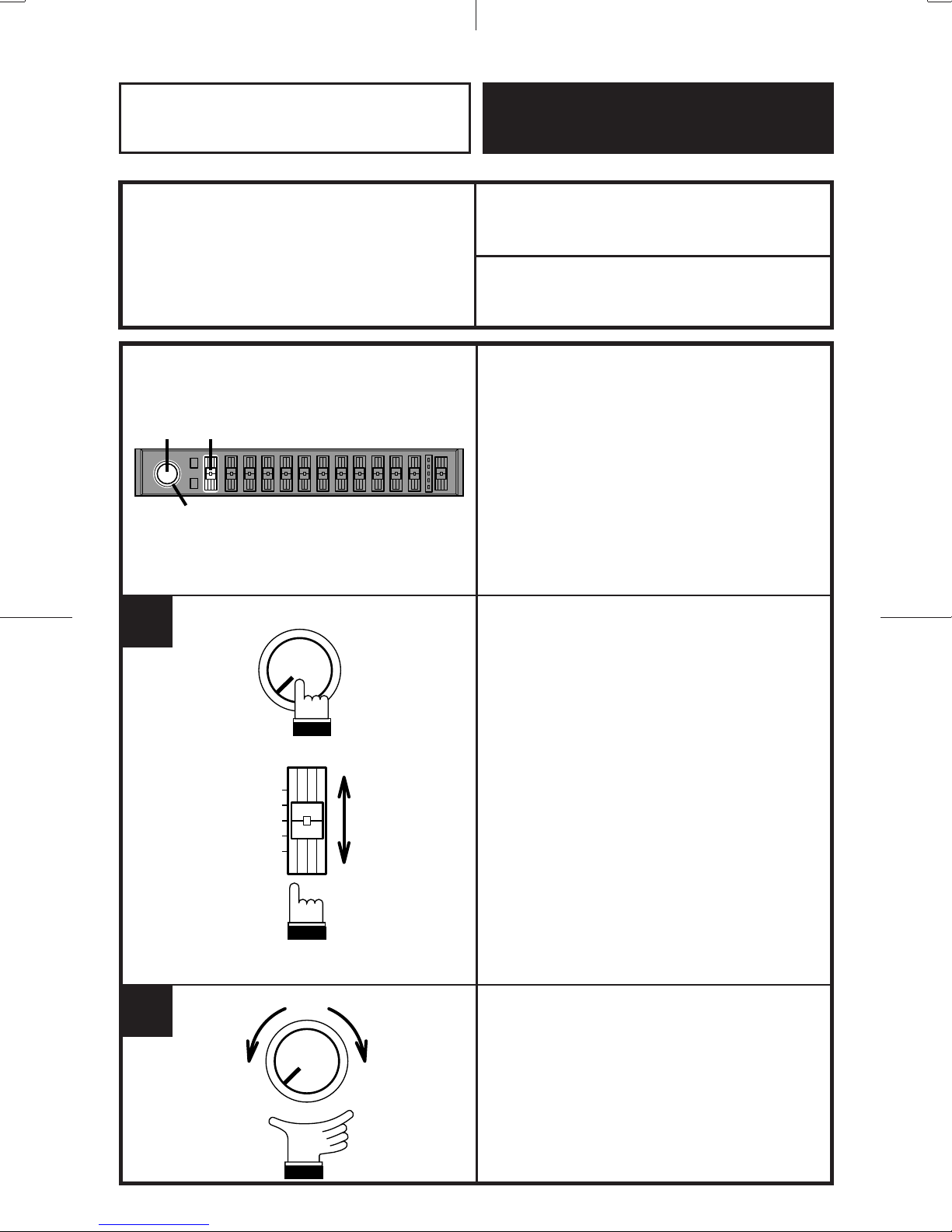
Réglage de niveau du sub-
woofer
L'ERE-G180 assure à l'utilisateur un contrôle
complet de la sortie du sub-woofer. Non
seulement le niveau de sortie peut être réglé
à +15 dB mais aussi la fréquence du point de
croisement est continûment réglable, l'entrée
peut être additionnée en utilisant le commu-
tateur STEREO/MONO et un commutateur
de PHASE fournit un déphasage de 0 ou
180°.
Quand le commutateur SUBWOOFER ON/
OFF est sur la position désactivée (OFF), le
témoin lumineux (LED) sur la commande
SUBWOOFER LEVEL s'éteindra. Dans ce
mode, les sorties avant et arrière seront
signaux de gamme complète avec non-signal
à la sortie de sub-woofer.
Quand le commutateur SUBWOOFER ON/
OFF est sur la position activée (ON), le
témoin lumineux (LED) sur la commande
SUBWOOFER LEVEL s'allumera en ambre.
Dans ce mode, les sorties avant et arrière
seront passe-haut et la sortie de sub-woofer
recevra des signaux passe-bas.
Remarque:Appuyer sur le commutateur
SUBWOOFER ON/OFF pour
régler le sub-woofer en mode
ON. Appuyer de nouveau pour
régler à OFF.
Sélectionner une fréquence de transfert entre
50 et 120 Hz en utilisant la commande
CROSSOVER FREQUENCY.
Fonctionnement Operación
Conexión y desconexión de
la alimentación
El ERE-G180 se encenderá y apagará
automáticamente cuando usted encienda o
apague su unidad principal.
Ajuste de nivel del altavoz
de frecuencias ultrabajas
El ERE-G180 ofrece al usuario control total
de la salida del altavoz de frecuencias
ultrabajas. No sólo el nivel de salida puede
ajustarse a +15 dB, también la frecuencia del
punto de cruce es de ajuste continuo, la
entrada puede ser sumada usando el
interruptor STEREO/MONO y el interruptor
de PHASE proporciona un desfase de 0 o
180°.
Cuando el interruptor SUBWOOFER ON/OFF
se encuentre en posición desactivada (OFF)
el LED del control SUBWOOFER LEVEL se
apagará. En este modo, las salidas delantera
y trasera serán señales de gama completa
con ausencia de señal a la salida del altavoz
de frecuencias ultrabajas.
Cuando el interruptor SUBWOOFER ON/OFF
se encuentre en posición activada (ON) el
LED del control SUBWOOFER LEVEL se
iluminará de color ámbar. En este modo, las
salidas delantera y trasera serán de paso alto
y la salida del altavoz de frecuencias
ultrabajas recibirá las señales de paso bajo.
Nota: Presione el interruptor SUBWOOFER
ON/OFF para activar el modo del
altavoz de frecuencias ultrabajas.
Presione de nuevo el interruptor para
desactivarlo.
Usando el control CROSSOVER
FREQUENCY, seleccione una frecuencia de
cruce entre 50 y 120 Hz.

8
EnglishEnglish/Français/Español
1
Adjusting the Equalizer and
Defeat Controls
The EQUALIZER DEFEAT switch will be
illuminated green when it is in the "OFF"
position. In this mode, all the equalizer
settings are in effect. The LED indicators on
the EQUALIZER controls will be on.
Note: The EQUALIZER DEFEAT switch will
be illuminated amber when it is in the
"ON" position. In this mode, the
equalizer settings will not effect the
output (except for BBE if turned on).
The LED indicators on the EQUALIZER
controls will be off.
2
11
DEFEAT
EQ
+
12
–12
Operation

9
Français Español
English/Français/Español
Réglage des commandes
d'égaliseur et d'annulation
Quand le commutateur EQUALIZER DEFEAT
est sur la position désactivée (OFF), il
s'allumera en vert. Dans ce mode, tous les
réglages d'égaliseur produisent leurs effets.
Les indicateurs lumineux (LED) sur les
commandes d'égaliseur (EQUALIZER) seront
allumés.
Remarque: Quand le commutateur
EQUALIZER DEFEAT est sur la
position activée (ON) il s'allumera
en ambre. Dans ce mode, les
réglages d'égaliseur n'effectue-
ront pas la sortie (excepté pour
BBE, si activé). Les indicateurs
lumineux (LED) sur les comman-
des d'égaliseur (EQUALIZER)
seront éteints.
Ajuste de los controles de
ecualizador y cancelación de
efecto
El interruptor EQUALIZER DEFEAT se ilumina
de color verde cuando está en la posición
"OFF". En este modo, todos los ajustes del
ecualizador estarán activos. Los indicadores
LED de los controles del ecualizador
(EQUALIZER) se iluminarán.
Nota: El interruptor EQUALIZER DEFEAT se
ilumina de color ámbar cuando está en
la posición "ON". En este modo, los
ajustes del ecualizador no efectuarán la
salida (excepto para BBE, si está
activado). Los indicadores LED de los
controles del ecualizador (EQUALIZER)
se apagarán.
Fonctionnement Operación

10
EnglishEnglish/Français/Español
Adjusting the Volume/Tone/
Fader Controls
Adjust the volume and tone controls of your
head unit and the FADER control on the ERE-
G180 to suit your listening preference.
Regardless of the EQUALIZER DEFEAT
switch position, the OUTPUT LEVEL indica-
tors will light up in response to the input signal
levels. The input signal level is controlled by
the volume control of your head unit.
Note: If the red LED lights up continuously,
the output of the ERE-G180 could be
distorted. Reduce the input level using
the head units volume control. The red
LED should only light intermittently for
optimum sound quality.
Selecting the BBE Mode
Press the BBE switch to set the ERE-G180 to
the BBE mode.
With each press, the BBE is toggled On or Off.
Notes:
• When the BBE switch is illuminated in
amber, the BBE is in effect.
• The BBE switch will be illuminated amber
when it is in the "ON" position.
1
1
Operation
F
R
FADER
BBE
1
1

11
Français Español
English/Français/Español
Ajuste des commandes de
volume/tonalité/fondu
Ajuster les commandes de volume et de
tonalité de l'unité principale et la commande
FADER sur l'ERE-G180 selon les préférences
d'écoute.
Indépendamment de la position du commuta-
teur EQUALIZER DEFEAT, les indicateurs de
niveau de sortie (OUTPUT LEVEL) s'allument
en réponse aux niveaux du signal d'entrée. Le
niveau du signal d'entrée est commandé par
la commande de volume de l'unité principale.
Remarque: Si l'indicateur lumineux (LED)
rouge s'allume continûment, la
sortie de l'ERE-G180 peut être
déformée. Réduire le niveau
d'entrée en utilisant la commande
de volume des unités principales.
L'indicateur lumineux (LED)
rouge doit s'allumer seulement
par intermittence pour une
optimale qualité sonore.
Sélection du mode BBE
Appuyer sur le commutateur BBE pour régler
l'ERE-G180 en mode BBE.
A chaque pression sur la touche, BBE sera
activé ou désactivé.
Remarques:
• Si le commutateur BBE s'allume en ambre,
le mode BBE est activé.
• Le commutateur BBE s'allumera en ambre
sur la position "ON".
Ajuste de los controles de
volumen/tono/desvanecedor
Ajuste los controles de volumen y tono de su
unidad principal, y el control FADER del ERE-
G180, según su gusto personal.
Independientemente de la posición del
interruptor EQUALIZER DEFEAT, los
indicadores de nivel de salida (OUTPUT
LEVEL) se iluminarán en respuesta a los
niveles de la señal de entrada. El nivel de la
señal de entrada se regula mediante el
control de volumen de la unidad principal.
Nota: Si el indicador LED rojo está continua-
mente encendido, la salida del ERE-
G180 puede ser distorsionada.
Reduzca el nivel de entrada utilizando
el control de volumen de las unidades
principales. El indicador LED rojo debe
encenderse solamente de forma
intermitente para obtener una calidad
sonora óptima.
Selección de modo BBE
Presione el interruptor BBE para ajustar el
ERE-G180 en modo BBE.
Con cada presión BBE es activado o
desactivado.
Notas:
• Si el conmutador BBE se ilumina en color
ámbar, el modo BBE está activado.
• El conmutador BBE se iluminará en color
ámbar cuando esté en la posición "ON".
Fonctionnement Operación

12
English/Français/Español English
Number of Bands/Nombre de bandes/Número
de bandas .......................................................
Boost/Cut Range/
Gamme d’accentuation/atténuation/
Margen de incremento/corte ...........................
Equalizer Center Frequencies/Fréquences
centrales d’égaliseur/Frecuencias centrales
del ecualizador ................................................
Frequency Response/Réponse en fréquence/
Respuesta de frecuencia ................................
Signal-to-Noise Ratio/Rapport signal-bruit/
Relación señal-ruido .......................................
Crossover Frequency/Fréquence de transfert/
Frecuencia de cruce .......................................
Crossover Slope/Pente de coupure/Curva de
cruce ...............................................................
Subwoofer Level Control/
Commande de niveau du subwoofer/
Control de nivel del altavoz de frecuencias
ultrabajas ........................................................
Input Impedance/Impédance d’entrée/
Impedancia de entrada ...................................
Output Impedance/Impédance de sortie/
Impedancia de salida ......................................
Dimensions (W x H x D)/Dimensions (L x H x
P)/Dimensiones (an. x al. x pr.).......................
Weight/Poids/Peso..........................................
Specifications
.................................................................... 11
.............................................................±12 dB
....... 31.5 Hz, 63 Hz, 125 Hz, 190 Hz, 250 Hz,
500 Hz, 1 kHz, 2.2 kHz, 4.5 kHz, 9 kHz, 18 kHz
..................................20 Hz to 30 kHz (–1 dB)
................................................100 dB (IHF-A)
.....50 Hz to 120 Hz (Continuously adjustable)
................... LOW 18 dB/oct. HIGH 12 dB/oct.
................................................ 0 dB to +15 dB
................................................10k ohms MIN.
.................................................. 1k ohm MAX.
............... 178 x 25 x 130mm (7" x 1" x 5-1/8")
............................................0.65 kg (1 lb. 7 oz.)
Note: Due to product improvement, specifica-
tions and design are subject to change
without notice.

28
82
58
ALPINE ELECTRONICS, INC.
Tokyo office: 1-1-8 Nishi Gotanda,
Shinagawa-ku, Tokyo 141, Japan
Tel.: (03) 3494-1101
ALPINE ELECTRONICS OF AMERICA, INC.
19145 Gramercy Place, Torrance,
California 90501, U.S.A.
Tel.: (310) 326-8000
ALPINE ELECTRONICS OF CANADA, INC.
605 Alden Road, Markham,
Ontario L3R 3L5, Canada
Tel.: (905) 475-7280
ALPINE ELECTRONICS OF AUSTRALIA PTY. LTD.
Redwood Gardens Estate, 3 Plane-tree
Avenue, Dingley, Victoria 3172, Australia
Tel.: 3-551-8811
ALPINE ELECTRONICS GmbH
Brandenburger Strasse 2-6 D-40880 Ratingen,
Germany
Tel.: 02102-45 50
ALPINE ITALIA S.p.A.
Via C. Colombo 8, 20090 Trezzano Sul
Naviglio MI, Italy
Tel.: 02-48 40 16 24
ALPINE ELECTRONICS FRANCE S.A.R.L.
98, Rue De La Belle Etoile, Z.I. Paris Nord II
B.P. 50016 F-95945, Roissy,
Charles de Gaulle Cedex, France
Tel.: 01-48 63 89 89
ALPINE ELECTRONICS OF U. K., LTD.
13 Tanners Drive, Blakelands,
Milton Keynes GB-MK14 5BU, U.K.
Tel.: 0908-61 15 56
ALPINE ELECTRONICS DE ESPAÑA, S.A.
Portal De Gamarra 36, Pabellón 32
01013 Vitoria (Alava) - Apdo. 133, Spain
Tel.: 34-45-283588
R
68P61487W42-O
Printed in Korea

mLPINt,
LIMITED WARRANTY
ALPINE ELECTRONICS OF AMERICA, INC. AND ALPINE OF CANADA INC. (“Alpine”), are dedicated to
quality craftsmanshrp and are pleased to offer this Warranty. We suggest that you read it thoroughly. Should you have
any questrons, please contact your Dealer or contact Alpine at one of the telephone numbers listed below.
l
PROOUCTS COVERED:
This Warranty covers Car Audro Products and Related
Accessones (“the product”). Products purchased in the
Canada are covered only in the Canada Products pur-
chased rn the U S.A. are covered only In the U S.A.
product was shopped to an Authorized Alpine Ser-
vrce Center or Alpine, Alpine WIIIpay the return ship-
ping charges.
l
LENGTH OF WARRANTY:
ThusWarranty is In effect for one year from the date of
the first consumer purchase.
@ You should provide a detailed description of the
problem(s) for which service is required.
@ You must supply proof of your purchase of the prod-
uct.
@ You must package the product securely to avoid
damage during shipment
l
LIFETIME TAPE HEAD WARRANTY:
All Alprne Car Audro analog tape heads are warranted
for life agarnst manufacturing defects causing failure.
l
LIFETIME ORB CONNECTOR WARRANTY:
All Alpine Car Audio Quick Release Bracket connectors
are warranted for life agarnst manufacturrng defects
causrng farlure
l
HOW WE LIMIT IMPLIED WARRANTIES:
ANY IMPLIED WARRANTIES INCLUDING FITNESS FOR
USE AND MERCHANTABILITY ARE LIMITED IN DURA-
TION TO THE PERIOD OF THE EXPRESS WARRANTY
SET FORTH ABOVE AND NO PERSON IS AUTHORIZED
TO ASSUME FOR ALPINE ANY OTHER LIABILITY IN
CONNECTION WITH THE SALE OF THE PRODUCT.
l
WHO IS COVERED:
This Warranty only covers the orrginal purchaser of the
product, who must reside rn the Unrted States, Puerto
RICOor Canada.
l
WHAT IS COVERED:
This Warranty covers defects rn materials or workman-
ship (parts and labor) rn the product
l
WHAT IS NOT COVERED:
This Warranty does not cover the followrng:
@ Damage occurrrng durrng shrpment of the product
to Alpine for repair (claims must be presented to the
carrrer)
@ Damage caused by accident, abuse, negligence,
misuse, Improper operation or failure to follow in-
structions contained rn the Owner’s manual
@ Damage caused by act of God, including without
limitation, earthquake, fire, flood, storms or other
acts of nature
l
HOW WE EXCLUDE CERTAIN DAMAGES:
ALPINE EXPRESSLY DISCLAIMS LIABILITY FOR INCI-
DENTAL AND CONSEQUENTiAL DAMAGES CAUSED
BY THE PRODUCT. THE TERM “INCIDENTAL DAM-
AGES” REFERS TO EXPENSES OF TRANSPORTING
THE PRODUCT TO THE ALPINE SERVICE CENTER,
LOSS OF THE ORIGINAL PURCHASER’S TIME, LOSS
OF THE USE OF THE PRODUCT, BUS FARES, CAR
RENTALS OR OTHERS COSTS RELATING TO THE
CARE AND CUSTODY OF THE PRODUCT. THE TERM
“CONSEQUENTIAL DAMAGES” REFERS TO THE COST
OF REPAIRING OR REPLACING OTHER PROPERTY
WHICH IS DAMAGED WHEN THIS PRODUCT DOES
NOT WORK PROPERLY. THE REMEDIES PROVIDED
UNDER THIS WARRANTY ARE EXCLUSIVE AND IN
LIEU OF ALL OTHERS.
l
HOW STATE/PROVINCIAL LAW RELATES TO THE
WARRANTY:
@ Any cost or expense related to the removal or rein-
stallatron of the product.
@ Service performed by an unauthorized person, com-
pany or assocratron
@ Any product which has the serial number defaced,
altered or removed.
@ Any product whrch has been adjusted, altered or
modified wrthout Alprne’s consent.
@I Any product not distributed by Alprne wrthin the
Unrted States, Puerto Rico or Canada.
@ Any product not purchased from an Authorized Al-
prne Dealer
This Warranty gives you specific legal rights, and you
may also have other rrghts which vary from state to state
and province to province. In addition, some states/prov-
inces do not allow limitations on how long an implied
warranty lasts, and some do not allow the exclusion or
limitation of incrdental or consequential damages. Ac-
cordingly, limitatrons as to these matters contained
herein may not apply to you
l
IN CANADA ONLY:
l
HOW TO OBTAIN WARRANTY SERVICE:
@ You are responsible for delivery of the product to an
Authorrzed Alpine Service Center or Alpine for repair
and for payment of any initral shipping charges. Al-
pine wrll, at its option, reparr or replace the product
wrth a new or reconditioned product without charge.
If the reparrs are covered by the warranty, and if the
This Warranty is not valrd unless your Alpine car audio
product has been installed in your vehicle by an Autho-
rized Installation Center, and this warranty stamped
upon installation by the installation center.
l
HOW TO CONTACT CUSTOMER SERVICE:
Should the product require service, please call the fol-
lowing number for your nearest Authorized Alpine Ser-
vrce Center.
U.S.A. l-800-ALPINE-1 (l-800-257-4831)
CANADA l-800-ALPINE-1 (l-800-257-4831)
Alpine Electronics of America, Inc., 19145 Gramercy Place, Torrance, California 90501, U.S.A.
Alpine Electronics of Canada, Inc., Suite 203, 7300 Warden Ave. Markham, Ontarro L3R 9Z6, Canada
54641874WQ1 -E
3354010602-E

GARANTIE LlMlTiE
Fldeles a leur engagement de ne fournlr que des products de qualite, ALPINE ELECTRONIQUE DE L’AMERIQUE INC. et
ALPINE ELECTRONIQUE DU CANADA INC (Alptne) sent heureuses de vous offrlr cette garantie Nous vous sugg&ons de le
lyre attentlvement et en en&r SI vous avez la molndre question, veulllez contacter I’un de nos concesslonnalres ou appeler
dlrectement Alpine au numeros Llste wdessous
l PRODUITS COUVERT PAR LA GARANTIE
Cette garantle cowre les products audio pour I’auto et les
accesolres correspondants Elle ne cowre les products que
dans le pays olj II ant Bte acheles
l DUR6E DE LA GARANTIE
Cette garantle est en vlgueur pendant un an & partlr de la
date du prerner achat du client
.GARANTIE A VIE DES TeTES DE LECTURE DES
MAGNETOPHONES A CASSElTES
Toutes les t&es de lecture des magetophones & cassettes
analoglques pour l’auto Alplne sent garanties g vie contre
les defauts de fabrlcatlon qui provoquent un panne
.GARANTIE A VIE DES CONNECTEURS DE SUP-
PORT A DECLENCHEMENT RAPIDE
Tous les connecteurs de support B d&&nchement raplde
des products audio pour l’auto Alplne sent garantls B vie
contre les defauts de fabrlcatlon qua provoquent un panne
l PERSONNEL PROTlkGtES PAR LA GARANTIE
Seul i’acheteur orIgInal du product. S’II r&stsde aux Etats-
Unls, a Porte RICO ou au Canada, peut se prevalolr de la
garantle
l CE WI EST COUVERT
Cette garantle couvre tous les defauts de matenaux et de
fabrication (p~&ces et main d‘ceuvre) du product
l CE GUI N’EST PAS COUVERT
Cette garantle ne couwe pas ce qul suit
@I Les dommages suwenus durant le transport des
products renvoyes a Alpine pour &re v&pares (les
r&clamations dwent &tie adressees au transporteur),
@ Les dommages quf sent la consequence d’un accident,
de mauvals traltements de negligence. du mauvals us-
age, de I’utillsation mpropre. ou du fait de ne pas avoir
SUIVI les wtructlons du Guide de I’ut,llsateur,
@ Les dommages dus a la force majeure, notamment aux
tremblements de terre au feu. aux Inondatlons, aux
tempetes ou aux autres cataclysmes natureis,
@ Les frals ou les depenses relatlfs a I’enl&ement ou B la
r&nstallatlon du product,
@ Les serwces rendus par une personne. physique ou mo-
rale non autorisee.
@ Les produlis doni le num&o de s&rle a BtB efface,
modlfi& ou retlre.
6 Les products qul ant ele adaptes ou modltles saris le
consentement d’Alplne.
@ Les products qui ne sent pas dlstrlbues par Alpine aux
Etats-Unls. B Porte RICO ou au Canada.
@ Les products qul n’ont pas Bte ache& par l’entremlse
d’un concesslonnalre Alpine autowe.
WZOMMENT SE PRCVALOIR DE LA GARANTIE
@I II vous faut remettre le product necessltant des
reparations a un centre de serwe autor~se Alpine ou B
Alpine meme et en assumer les frals dB transport Alpine
a le cholx entre &parer le product ou le remplacer par un
product neuf ou r&se le tout saris frais pour vous SI les
reparations sent couvertes par la garantie et SI le produit
a et8 envoy6 a un centre de serwx Alpine ou a Alpine, le
palement des frals de r&exp&dltlon du produit incombe
AlpIne
@ Vous devez dormer une descrlptwn detaillee des
problemes qul sent g I’ortglne de votre demande de
r6paratlon.
@ Vow devez ]olndre la preuve de votre achat du produit.
@I Vous devez emballer solgneusement le produit pour
Bwter tout dommage durant son transport.
l LIMITATION DES GARANTIES TACITES
LA DURiE DE TOUTES LES GARANTIES TACITIES. Y
COMPRIS LA GARANTIE D’ADAPTATION A L’UTILISATION
ET LA GARANTIE DE QUALlTi LOYALE ET MARCHANDE.
EST LlMlTiE A CELLE DE LA GARANTIE EXPRESSE
DiTERMlNiE Cl-DESSUS PERSONNE N’EST AUTORlSi A
ENGAGER AUTREMENT LA RESPONSABlLlTi D’ALPINE
EN VERTU DE LA VENTE D’UN PRODUIT
l EXCLUSIONS DE LA GARANTIE
ALPINE STIPULE EXPRESSiMENT QU’ELLE N’EST PAS
RESPONSABLE DES DOMMAGES DOMMAGES-INTiRiTS
ET DOMMAGES INDIRECTS PROVOQUiS PAR LE
PRODUIT LES DOMMAGES DOMMAGES-INT&cTS SONT
LES FRAIS DE TRANSPORT DU PRODUIT VERS UN CEN-
TRE DE SERVICE ALPINE, LA PERTE DE TEMPS DE
L’ACHETEUR ORIGINAL, LA PERTE D’UTILISATION DU
PRODUIT, LES BILLETS D’AUTOBUS. LA LOCATION DE
VOITURES ET TOUS LES AUTRES FRAIS LI& A LA GARDE
DU PRODUIT
LES DOMMAGES INDIRECTS SONT LES FRAIS DE
RiPARATlON OU DE REMPLACEMENT D’AUTRES BIENS
ENDOMMAGES SUITE AU MAUVAIS FONCTIONNEMENT
ml! PRODlIlT
LESRECOURSPREVUSPARLESPRiSENTESEXCLUENT
ET REMPLACENT TOUTE AUTRE FORME DE RECOURS.
l LIEN ENTRE LA GARANTIE ET LA LOI
La garantle vous donne des droits sp&fiques, mals vous
pouvez aussf ]ou~r d’autres drolts. qul varlent d’un Btat ou
d’une province a l’autre En outre, certains &tats et certaines
provinces lnterdlsent de llmlter la d&e des garantles
tacltes ou d‘exclure les dommages accessoves ou IndIrects.
Dans ce cas, les llmltes et les exclusions de la garantie
peuvent ne pas s’appllquer a vous
l CLAUSE APPLICABLE AU CANADA SEULEMENT
Pour que la garantle soIt valable, II faut qu’un centre
d’nstallatlon autowe alt lnstall& le systeme audio pour I’auto
dans votre v&hicule et qu’ll alt ensuite appose son cachet
sur la garantie
l
NUMEROS D’APPEL DU SERVICE A LA CLIENTELE
SI vow aver besoln de nos services. veulllez appeler le cen-
tre de serwce autorIse Alpine le plus proche.
U.S.A. l-800-ALPINE-1 (l-800-257-4831)
CANADA l-800-ALPINE-1 (l-800-257-4831)
Alpine electronique de L’AmBrique, Inc.,
19145 Gramercy Place, Torrance, California 90501, U S A
Alpine hectronique du Canada, Inc.,
Suite 203, 7300 Warden Ave Markham, Ontario L3R 9Z6, Canada

ERE-G180
1l-Band Graphic Equalizer
GUIDE FOR INSTALLATION AND CONNECTIONS
GUIDE D’INSTALLATION ET DE CONNEXIONS
GUIA DE INSTALACION Y CONEXIONES
Please read this GUIDE FOR INSTALLATION AND
CONNECTIONS and the OWNER’S MANUAL thor-
oughly to familiarize yourself with each control and
function. We at ALPINE hope that your new ERE-
G180 will give you many years of listening enjoyment.
In case of problems when installing your unit, please
contact your authorized ALPINE dealer.
Priere de lire attentivement ce GUIDE D’INSTALLA-
TION ET DE CONNEXIONS et le MODE D’EMPLOI
pour se familiariser avec chaque commande et fonc-
tion. Chez Alpine, nous esperons que le nouveau
ERE-G180 donnera de nombreuses annees de plai-
sir d’ecoute.
En cas de problemes lors de I’installation de I’unite,
priere de contacter le revendeur agree dIALPINE.
Afin de familiarizarse con 10scontroles yfunciones de
la unidad, lea detenidamente esta GUIA DE
INSTALACION Y CONEXIONES junto con el
MANUAL DE OPERACION. Nosotros en ALPINE
esperamos quesu nuevo ERE-Gi 80 lebrinde muchos
ados de placer auditivo.
En case de presentarse algun problema durante la
instalacion de la unidad, tome contact0 con su
distribuidor autorizado ALPINE.
English
1IMPORTANT
Please record the serial number of your unit
in the space provided on the back cover of
Owner’s Manual and keep it as a permanent
record. The serial number plate is located on
the bottom of the unit.
Franpais
1IMPORTANT
Enregistrer le numero de serie de I’appareil
dans I’espace prevu audosdu moded’emploi
et le conserver en permanence. La plaque
de numero de serie est sit&e au fond de
I’appareil.
EspaAol
1IMPORTANTE
Anote el numero de serie de su unidad en el
espacio proporcionado en la cubierta poste-
rior del manual de operation, y conservelo
corn0 un registro permanente. La placa con
el numero de serie esta ubicada en la pane
inferior de la unidad. I
68P61487W41-0
3351156801-O
Printed in Korea

Dashboard
Tableau de bord
Mounting Bracket
Support de montage
Soporte de montaje
Hex Bolts (M4 x 8)
Boulons a six pans (M4 x 8)
Pernos hexagonales (M4 x 8)
Tornillos autorroscantes(M5 x 20)
In Dash or In Console Installation/Installation dans le tableau de bord ou dans la console/
Instalaci6n en el tablero de instrumentos o en la consola
Under-Dash lnstallationllnstallation sous le tableau de botinstalaci6n debajo del tablero de instrumentos
Mounting Bracket
Mounting Opening Support de montage
O~~~~ure de montage Soporte de montaje
Front Trim Plate
Abertura de montaje
\
Plaque de garniture avant
piaca -yvJ,
‘,“+ c
47 Q \
\
Console
/ Console
Consola

NOTE:
+I 2V is required on this line to turn on the ERE-G180. If your head unit does not have a remote-on or power-antenna turn-on wire, a SPST switch must
be connected between an ignition source and this terminal. Then, the ERE-G180 can be turned on.
REMARQUE:
Une tension de +I 2V est necessaire sur cette ligne pour mettre I’ERE-G180 sous tension. Si I’unite prircipale n’a pas de cable de mise sous tension
telecommandee ou de cable de mise sous tension de I’antenne alimentee, un commutateur SPST doit etre connecte entre une source d’allumage et
cette borne. Ensuite, I’ERE-G180 peut Btre mis sous tension.
NOTA:
Esta linea requiere +12V para encender el ERE-G180. Si su unidad principal no esta provista de un alambre de encendido automatic0 o de antena
electrica, sera necesario conectar un interruptor SPST entre una fuente de encendido y este terminal. Solo entonces sera posible encender el ERE-
G180.

‘P.
Front Rear
Avant Arrihre
Delantero Trasero
Subwoofers
Sub-woofers
Altavoces de frecuencias
ultrabajas
SpeakersMaut-parleurs/Altavoces

English
0 Remote On Lead (BLUE/WHITE)
Connect this lead to the remote turn-on lead of your head unit. Applying (+)12V to this lead turns on the
ERE-G180. If your head unit has a power antenna output that provides (+)12V when the unit power is
turned on, you may use that lead to turn the ERE-G180 on.
0 Ground Lead (BLACK)
Connect this lead to a good chassis ground.
Verify this point to be a true ground by checking continuity between this point and the negative terminal of
the vehicle’s battery. For best results and immunity to vehicle induced noise, ground all audio components
at the same ground point.
NOTE:
Secure the ground lead of the unit to bare metal on the car chassis using a sheet metal screw
0 Battery Lead (YELLOW)
Connect this lead to the positive (+) post of the vehicle’s battery
@ Front Output Connector
(to front speaker amplifier or signal processor)
0 Rear Output Connector
(to rear speaker amplifier or signal processor)
@ Subwoofer Output Connector
(to subwoofer amplifier or signal processor)
0 Input Connector
@ PHASE Switch
The acoustical characteristics of different cars varies. When using subwoofers, standing waves may be
produced at low frequencies. These standing waves can cause cancellation and loss of performance at the
low end. To set the PHASE switch, listen to the system while switching the phase to 0 or 180”. Leave it in
the position which provides the best bass response.
@ STEREO/MONO Switch
52
m
PHASE
180” 0”
If you have one subwoofer for your system, set the STEREO/MONO switch to the MONO position. When
using two or more subwoofers, the switch may be set to either MONO or STEREO. In the STEREO mode,
you may gain some sound separation (depending upon the music material). On the other hand, in the
MONO position, the subwoofers will share the load more equally and can play louder. Experiment to see
which sounds better for your application.
NOTE:
The PHASE and STEREO/MONO switches should be set before the installation is completed
Other manuals for ERE-G180
1
Table of contents
Other Alpine Stereo Equalizer manuals
Popular Stereo Equalizer manuals by other brands

Alesis
Alesis DEQ230 Reference manual

Telex Pro Audio Group
Telex Pro Audio Group DN3600C Operators & service manual

MFJ
MFJ MFJ-616 instruction manual

Coyote Point Systems
Coyote Point Systems Equalizer Installation and administration guide

Behringer
Behringer MiniFBQ FBQ800 quick start guide

Rane
Rane SP 15 Operating and service manual