ALS 475 User manual

ALS Schmiertechnik GmbH & Co. KG ▪ Martinsgasse 2 ▪ 71063 Sindelfingen, Germany ▪ Phone +49 7031/879392
Fax +49 7031/879707 ▪Web: www.als-info.com ▪E-mail: in[email protected] 1
ALS lubricant dispenser
Type 475
Technical manual

ALS Schmiertechnik GmbH & Co. KG ▪ Martinsgasse 2 ▪ 71063 Sindelfingen, Germany ▪ Phone +49 7031/879392
Fax +49 7031/879707 ▪Web: www.als-info.com ▪E-mail: in[email protected] 2
Table of contents
1. Notes on instructions
2. Safety notes
2.1 Use
2.2 Warning and safety notes
2.3 Reports and certificates
3. Product description
3.1 General
3.2 Applications
3.3 Technical data
3.4 Properties and features
3.5 Structure and function
3.6 Liability
4. Storage
5. Installation
6. Commissioning
6.1 Commissioning the ALS lubricant dispenser
6.2 Using extension lines
6.3 Using lubricants
6.4 Recommissioning after idle time
6.5 Synchronization with machine operating time
6.6 Setting combinations for delivering lubricant
7. Maintenance
8. Optional accessories
9. Removal and replacement
10.Environment, disposal and recycling
11.Troubleshooting

ALS Schmiertechnik GmbH & Co. KG ▪ Martinsgasse 2 ▪ 71063 Sindelfingen, Germany ▪ Phone +49 7031/879392
Fax +49 7031/879707 ▪Web: www.als-info.com ▪E-mail: in[email protected] 3
1. Notes on instructions
These instructions contain important information about the ALS Type 475 lubricant dispenser and are used for safely
working with the product. Here you can find technical information about the structure, application, installation and
disposal of the ALS lubricant dispenser. If you have further questions, please contact ALS Schmiertechnik GmbH &
Co. KG or a sales partner.
The following designations are used in these instructions:
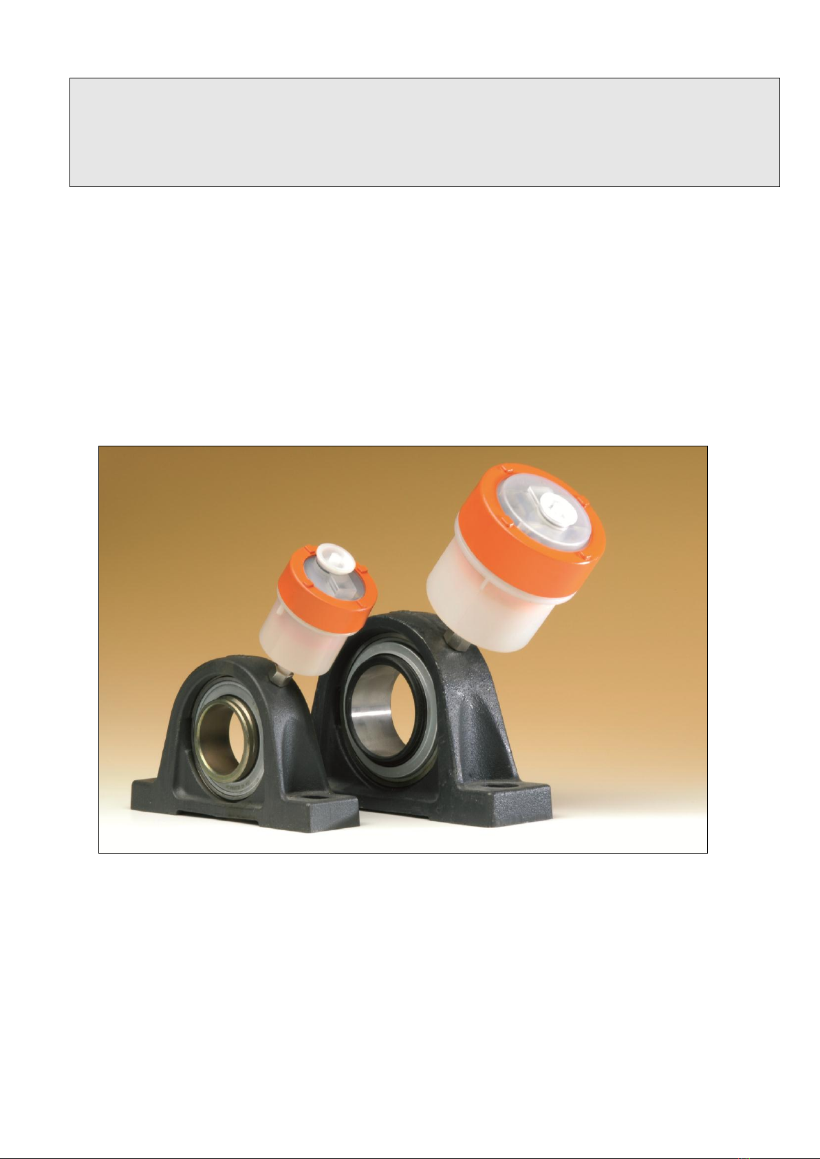
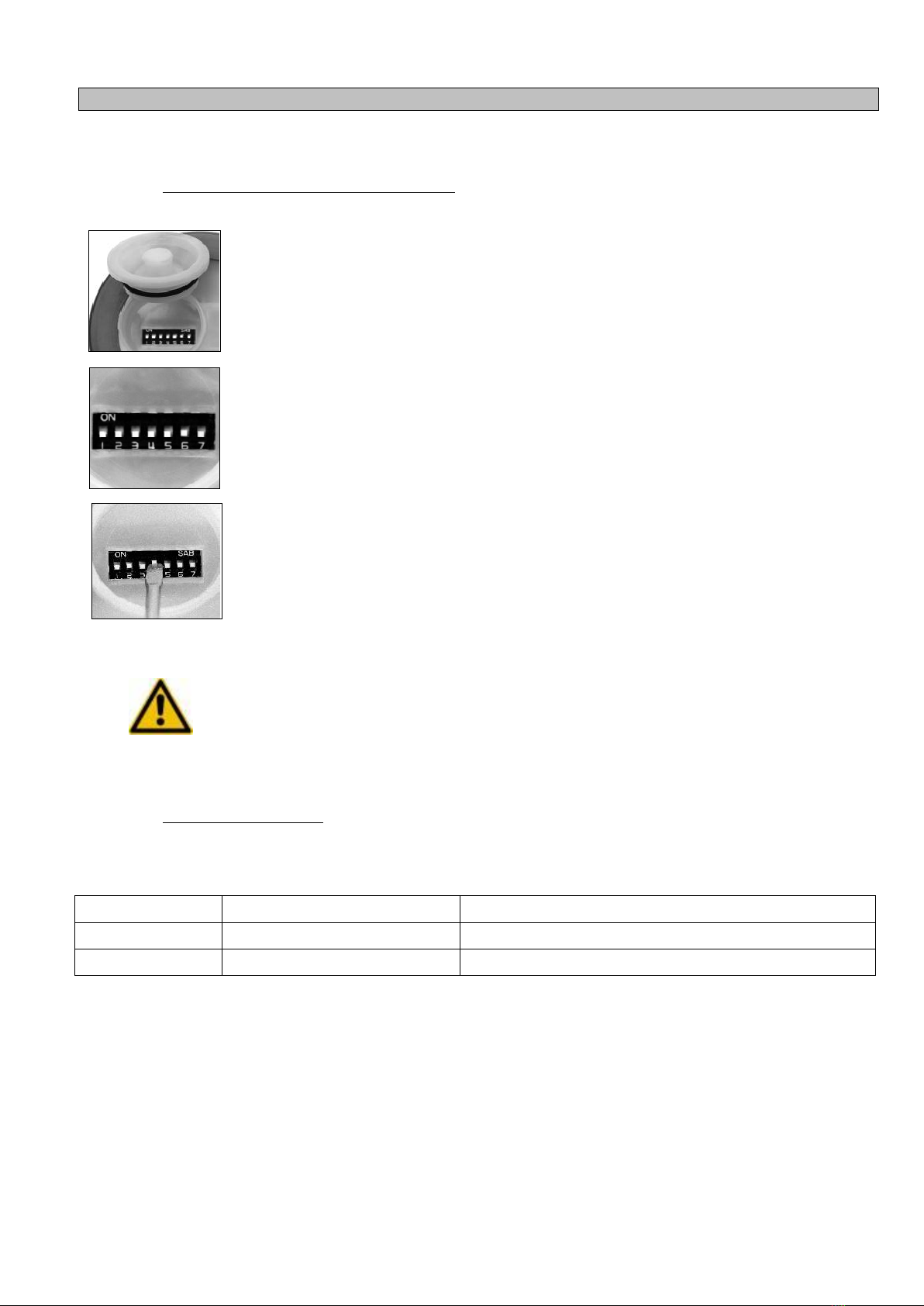
–Type 475: 460 cm³ volume
2. Safety notes
These safety notes do not claim to be complete. If you have questions or problems, please contact ALS
Schmiertechnik. The ALS lubricant dispenser has been developed to take into account current, state-of-the-art
technology and recognized safety-related regulations. The following general safety and warning notes in these
instructions should be followed at all times to prevent potential property damage or personal injury.
• Please read through these instructions carefully before using the ALS lubricant dispenser.
• If the product is resold, the technical manual should always be included. The newest version can be downloaded
from the ALS website, http://www.als-info.com.
• The technical ALS manual is available in German and English. Resellers from countries speaking other
languages are obligated to translate the information into the respective language properly.
2.1 Use
• The ALS lubricant dispenser is a technical tool developed to counteract wear and friction on machine
components using targeted lubrication.
• The ALS lubricant dispenser contributes to the safety of maintenance personnel since dangerous system
and machine areas have to be visited substantially less often due to fact lubricant is supplied automatically.
• Proper use requires that these instructions, and Chapter 2 on safety notes in particular, are read and
followed.
• The ALS lubricant dispenser is a product as defined by Machinery Directive 94/9/EC.
• Installation, commissioning, operation and maintenance should be carried out by trained, qualified
specialists since fundamental mechanical knowledge, knowledge of associated specialized terminology and
knowledge of applicable standards, stipulations and accident prevention measures are necessary.
2.2 Warning and safety notes
The warning notes provide information about the risk of personal injury and property damage. Please pay particular
attention to sections that contain this symbol:
• Indicates a risk to personal well-being that may result in severe injuries.

ALS Schmiertechnik GmbH & Co. KG ▪ Martinsgasse 2 ▪ 71063 Sindelfingen, Germany ▪ Phone +49 7031/879392
Fax +49 7031/879707 ▪Web: www.als-info.com ▪E-mail: in[email protected] 4
General safety notes:
• Please follow country-specific regulations regarding accident prevention and environmental protection and at the
workplace.
• Only use the ALS lubricant dispenser when it is in good condition and free of defects.
• Check the product for apparent defects, such as cracks in the hose and/or housing or missing screws and seals.
• The ALS lubricant dispenser must not be modified, opened or rebuilt, otherwise the manufacturer's warranty is void
and there is a risk of personal injury or damage to applications.
• The lid located on the top of the lubricant dispenser may only be opened by a specialist; the same applies to
removing the orange-colored ring.
• Pay attention to the safety data sheets for oils and greases.
• Only use the device in the application range specified in the technical data.
• The warranty is void if the product is installed improperly, is not used properly, is modified and/or is handled
improperly.
• Always shut off the power supply before installation or removal.
Safety notes for handling batteries:
• Prevent materials from the batteries from coming into contact with eyes, skin or clothing!
• Do not swallow materials or substances from batteries!
• Follow the safety data sheets!
• Pay attention to the temperature specifications for the batteries. Do not expose to open flame!
• Do not open batteries.
• Do not recharge the batteries!
• The batteries must be disposed of in accordance with regulations.
• Only the batteries specified by the manufacturer may be used.
Safety notes for installation and operation:
• Wear safety gloves, protective clothing and eye protection during installation.
• During installation, ensure that the lubricant dispenser and its components are securely in place.
• The safety notes and corresponding operating instructions must be followed when installing or providing
maintenance on machines and systems.
• Ensure that all seals and closures are correctly installed and are undamaged to prevent the
ingress of foreign material.

ALS Schmiertechnik GmbH & Co. KG ▪ Martinsgasse 2 ▪ 71063 Sindelfingen, Germany ▪ Phone +49 7031/879392
Fax +49 7031/879707 ▪Web: www.als-info.com ▪E-mail: in[email protected] 5
• Ensure that all electrical connections are assigned or closed off. Only put a fully installed product into operation.
• Check that the lubricant infeed is set up properly.
Safety notes for maintenance:
• Do not use any solvents or corrosive cleaning agents on ALS lubricant dispensers.
• Avoid electrostatic discharges by cleaning the lubricant dispenser from the outside with light pressure using an anti-
static cloth.
• The ALS lubricant dispenser must be disposed of in accordance with the respective national regulations.
Responsibilities of the operator:
The operator of the ALS lubricant dispenser must regularly inform personnel on the following topics:
• Following and using operating instructions and legal regulations.
• Properly operating and using the ALS lubricant dispenser.
• Following plant protection instructions and the operator's operating instructions.
• How to behave in case of an emergency.
2.3 Reports and certificates
Our products have been inspected by the following testing institutes:
• Fraunhofer Institute for Interfacial Engineering and Biotechnology
• Materials Testing Institute University of Stuttgart (FMPA), Baden-Wuerttemberg
Food and drink test values met
Legal regulations regarding food and drink were met
• ELMAC GmbH test lab
CE test certificate No. 76087-1BCD
• Germany's National Metrology Institute (PTB)
Certificate of conformity
• DEKRA EXAM GmbH
Technical authority for the safety of electrical equipment
EC type-examination certificate for areas prone to explosions
BVS 03 ATEX E 223 in accordance with Directive 94/9/EC
and 2nd addendum to test log BVS PP 03.2138 EC

ALS Schmiertechnik GmbH & Co. KG ▪ Martinsgasse 2 ▪ 71063 Sindelfingen, Germany ▪ Phone +49 7031/879392
Fax +49 7031/879707 ▪Web: www.als-info.com ▪E-mail: in[email protected] 6
3. Product description
3.1 General
The ALS lubricant dispenser is an electronically controlled lubricating device, which is driven electrochemically and
autonomously provides lubrication points with oil or grease. The ALS lubricant dispenser is simply screwed into the
threaded hole of a previously removed lubricating nipple or to an extension line. It delivers the specified lubricant
quantity over a particular time frame depending on the setting.
Designation
Volume
ALS Type 475
460 cm³
The ALS lubricant dispenser is also available in special versions with end position detection and/or a cable
connection. For more detailed information on this topic, see the "Synchronization with machine operating time" page
and the "Optional accessories" page.
3.2 Application
The ALS lubricant dispenser is suited for providing lubricant to individual lubrication points and/or hard-to-reach
lubrication points. It can be used at lubrication points belonging to:
–Roller bearings and sliding bearings
–Linear guides
–Shafts, spindles
Roller chains and toothed chains
–Seals
–Cables
–Open gears
3.3 Technical data
Type
475
Volume
460 cm³
Dimensions: Height x diameter
150 x 115 mm
Connecting thread
G ½
Empty weight
approx. 570 g
Pressure
approx. 0.2 –3 bar
Operating voltage
3 V
Battery capacity
6000 mAh
IP
64
Battery (standard design)
Varta Industrial 4006
Temperature range (approx.)
-30°C to +50°C
Relative humidity
30% - 80%, non-condensing
Lubrication duration, setting range
14 days to 18 months
Ex protection
BVS 03 ATEX E 223
(Not for the cable version)
Identification
II 2G Ex ib IIC T4 / T3 Gb
I M2 Ex ib I Mb
(Not for the cable version)

ALS Schmiertechnik GmbH & Co. KG ▪ Martinsgasse 2 ▪ 71063 Sindelfingen, Germany ▪ Phone +49 7031/879392
Fax +49 7031/879707 ▪Web: www.als-info.com ▪E-mail: in[email protected] 7
Standards and directives taken into account:
Directive 94/9/ EC
Equipment and protective systems intended for use in
potentially explosive atmospheres
Directive 98/37 EC
"Machine safety"
Directive 97/23 EC
"Pressure equipment safety"
Directive 89/336 EEC
"Electromagnetic compatibility"
EMC directive
3.4 Properties, features and advantages
▪ALS lubricant dispensers can either be delivered empty or filled with lubricant on the customer's request. The
lubricant can be ordered by the customer or be obtained directly from ALS Schmiertechnik.
▪Variable setting for the lubrication time and/or lubricant delivery quantity using DIP switches.
▪Function check using a red and green signal light (LED).
▪Constant pressure build-up from 0.2 bar to 3 bar.
▪Weather resistant, splash proof and corrosion resistant.
▪Temperature resistant from -30°C to +50°C.
▪Visual check of the fill level.
▪Optional synchronization to machine operating time possible.
▪Can be used in any orientation.
▪Optionally suited for underwater and wet areas as well.
▪After the operating time has passed, the lubricant dispenser is simply replaced with a new unit.
▪ALS lubricant dispensers are refillable and - after changing the battery compartment - can be reused.
▪Cost savings compared to manual lubrication.
▪Increases productivity by lowering the maintenance-related idle times of machines and systems.
▪Increased operating safety.
▪The bearing is sealed if the ALS lubricant dispenser is screwed in. This prevents dust and humidity from getting into
the bearing.
▪The lubrication point remains clean; there is no superfluous lubricant to affect system cleanliness or the
environment.
▪Electrically controlled via a microcontroller
▪Monitoring for the cup function
▪Visual display via a green flashing signal
▪Error display via a red LED

ALS Schmiertechnik GmbH & Co. KG ▪ Martinsgasse 2 ▪ 71063 Sindelfingen, Germany ▪ Phone +49 7031/879392
Fax +49 7031/879707 ▪Web: www.als-info.com ▪E-mail: in[email protected] 8
3.5 Structure and function
The lubricant dispenser is activated by setting DIP switch number 7 to the ON position. An electrochemical reaction
is triggered when the contacts close. The reaction releases nitrogen as an intermediate and causes a pressure build-
up in the nitrogen chamber. This pressure is transmitted to the plunger via a bellows. The plunger squeezes out the
lubricant which initiates lubrication. The lubricant delivery quantity is specified using the corresponding DIP switch
setting (see Settings table, page 13)
One red and one green signal light (LED) are located on top of the ALS lubricant dispenser. The green LED flashes
briefly when switch 7 is activated. Subsequently, the red LED normally flashes 15 times in a row until the actual
dosing or time setting has been made via the DIP switches. Then the red LED goes out and the green LED flashes
about every 30 seconds.
Cross-section:
3.6 Liability
The information, data and notes specified in this technical manual correspond to the most up-to-date status as of the
time of publication. Specifications, figures and descriptions can deviate from lubricant dispensers that have already
been delivered. Claims based on this cannot be enforced.
In the event of genuine product defects, subject to technical changes, ALS Schmiertechnik shall provide a
replacement free of charge. Additional claims by the purchaser, particularly claims for damages, shall be prohibited
to the extent that ALS Schmiertechnik did not cause the damage intentionally or as the result of gross negligence.
ALS assumes no liability for damages and disruptions caused by improper handling, misuse or failure to observe the
operating instructions for theALS lubricant dispenser.

ALS Schmiertechnik GmbH & Co. KG ▪ Martinsgasse 2 ▪ 71063 Sindelfingen, Germany ▪ Phone +49 7031/879392
Fax +49 7031/879707 ▪Web: www.als-info.com ▪E-mail: in[email protected] 9
4. Storage
• Storage conditions for the ALS lubricant dispenser and its components:
–Relative humidity of 30-60%, non-condensing
–No direct sunlight
–Storage temperature -30 to +50°C
–Storage period max. 3 months after receipt
• The lubricant can leak out in the event of improper storage.
• Store the ALS lubricant dispenser with the opening pointing downward.
• Before putting in storage, check that the lubricant dispenser is leak-tight.
• Stacking and improper storage can lead to malfunctions of the lubricant dispenser.
5. Installation
• Before installing the ALS lubricant dispenser, thoroughly lubricate the bearing position
using a manual grease gun in order to remove blockages and resin deposits that may be
present. In the process, the built-up pressure used to lubricate the bearing should not
exceed 0.5 bar. Then remove the lubricating nipple from the bearing.
• Now install the ALS lubricant dispenser by screwing it onto the bearing. If you need an
adapter for reducing the thread size from G1/4 to M 6x1, M 8x1, M 10x1 or G1/8, you can
find a large selection in our ALS product catalog. If a hose extension is needed for the
lubrication point, it should be filled ahead of time with the same lubricant that is in the
lubricant dispenser.
• Remove the protective cover and switch on the lubricant dispenser by activating the
desired DIP switch combination and DIP switch 7. The point is lubricated according to the
setting times (see p. 13).
In places with temperatures exceeding +60°C, distance the lubricant dispenser from the heat
source using a pipe extension (Caution: Pay attention to the line lengths, see p. 10). We
recommend using a pipe clamp (see Optional accessories, p. 15) when securing an ALS
lubricant dispenser in place sideways.
• The lubricant dispenser may be installed only by qualified specialists (see General safety
notes p. 3).
• Wear protective gloves, protective clothing and eye protection during installation.
• Do not install the lubricant dispenser directly at sources of vibration.
• Do not install the lubricant dispenser at heat sources.
• A protective hood is recommended for installation outdoors.
▪The ALS lubricant dispenser must not be installed in electromagnetic areas.

ALS Schmiertechnik GmbH & Co. KG ▪ Martinsgasse 2 ▪ 71063 Sindelfingen, Germany ▪ Phone +49 7031/879392
Fax +49 7031/879707 ▪Web: www.als-info.com ▪E-mail: in[email protected] 10
6. Commissioning
6.1 Commissioning the lubricant dispenser
Once the lubricant dispenser has been installed on the lubrication point, remove the
protective cover and switch on the lubricant dispenser. To do so, activate the DIP switch
according to the following instructions:
The "ON" designation only describes the switch-on direction and does not relate to the
function of DIP switch 1. Activate all of the DIP switches (No. 1-7). The green LED flashes
twice in a row every 8-10 seconds. The contact is closed and pressure begins building up.
This takes about 6-8 hours. As soon as lubricant comes out, put DIP switches No. 1-6 in the
"Off" position. DIP switch 7 remains in the "ON" position. Afterwards the red LED lights up 15
times in a row.
Now configure the desired dosing using the respective combination of DIP switches (see
Table, page 13). A green control light on top of the lubricant dispenser flashes approx. every
30 seconds. Now place the protective cover back on the DIP switches. The lubricant
dispenser has now been activated and configured.
• Check the ALS lubricant dispenser for external damage.
• Check the installation of the lubricant dispenser.
• Regularly check the fill level and the functionality of the lubricant dispenser.
• Check whether the DIP switch setting is correct.
• Protect from direct overheating.
6.2 Using extension lines
In the event that supply lines to the lubrication points are necessary, they should be pre-filled with the same lubricant
used in the lubricant dispenser. Do not mix different greases and/or oils!
Lubricant
Max. line length
Required min. internal diameter of line
Greases, pastes
0.5 m
6 mm
Oil
2 m
6 mm
The length of the supply lines depends on the consistency of the grease or the viscosity of the oil and on respective
environmental parameters.
Only one ALS lubricant dispenser should be used per lubrication point. A lubrication point requiring more lubricant
can also be supplied by 2 lubricant dispensers using a T-supply piece.

ALS Schmiertechnik GmbH & Co. KG ▪ Martinsgasse 2 ▪ 71063 Sindelfingen, Germany ▪ Phone +49 7031/879392
Fax +49 7031/879707 ▪Web: www.als-info.com ▪E-mail: in[email protected] 11
6.3 Using lubricants
The ALS lubricant dispenser is provided empty or filled. The ALS lubricant dispenser can be filled with greases up to
NLGI grade 2 or with oil in a viscosity range of ISO VG 46 to ISO VG 3000.
Important: Filling with oil: Operating time setting approx. 40% longer. In this case, it is recommended that a check
valve with 0.2 bar be used in front of the lubrication point to prevent the lines from running dry.
In the following table you can find a selection of common lubricants which cover a majority of applications. We would
be happy to consult with you regarding a suitable lubricant and we are available for information regarding special
fillings with the lubricant of your choice. In general, the specifications of the grease, oil and bearing manufacturer
should be followed. Product data sheets and safety data sheets are available upon request.
Here you can see a listing of our standard greases and oils:
Product designation
NLGI grade /
viscosity at 40°C
Temperature range /
pour point
Description
Multi-purpose grease
2
-30°C to +150°C
For roller bearings and sliding bearings
at low and/or high temperatures.
High-temperature
grease
1-2
-10°C to +180°C
For roller bearings and sliding bearings
for high operating temperatures.
Low-temperature
grease
2
-50°C to +150°C
For roller bearings and sliding bearings
at low temperatures.
Fluid grease
0
-20°C to +90°C
Specifically for applications at heavy-duty
friction points and more mixed friction
conditions.
Biodegradable grease
2
-20°C to +110°C
Environmentally friendly grease based on
vegetable oils.
USDA H1 food-safe
grease
1
- 40°C to +180°C
Color-neutral, taste-neutral, no smell.
Multi-purpose oil 46
46
-24°C
Universally applicable hydraulic oil.
Adhesive oil 220
220
-21°C
Wear-resistant, ropy special oil with
pronounced adhesion.
Adhesive oil 68
68
-27°C
Wear-resistant, ropy special oil with
pronounced adhesion.
USDA H1 food-safe oil
220
-33°C
Color-neutral, taste-neutral, no smell.
Biodegradable oil
68
-30°C
For nearly all hydraulic systems,
particularly when environmental
friendliness is required.
6.4 Recommissioning after idle time
The built-up pressure in the battery compartment remains present for about five days. Lubrication starts after a short
delay after reactivation of the ALS lubricant dispenser.
–Set switch 7 to "ON" for this.
–The green LED flashes twice in a row every 8-10 seconds.
–If necessary, set the lubrication duration again.

ALS Schmiertechnik GmbH & Co. KG ▪ Martinsgasse 2 ▪ 71063 Sindelfingen, Germany ▪ Phone +49 7031/879392
Fax +49 7031/879707 ▪Web: www.als-info.com ▪E-mail: in[email protected] 12
6.5 Synchronization to machine operating time
The ALS Type 475 lubricant dispenser with cable connection is recommended for machines that exhibit idle times
lasting from at least one week up to a maximum idle time of 6 months. However, longer idle times are possible
depending on the configured operating time for the ALS lubricant dispenser and the respective applications and
conditions. More information is available on request.
Installation:
The ALS Type 475 lubricant dispenser with cable connection has two contact screws. The
cable is connected to these screws with solder lugs as soon as the lubricant dispenser is
installed, thus connecting it to the machine control system. Required: A dry contact (NO
contact)
No additional power supply is required. Connected only by specialists. The maximum line
length between the lubricant dispenser and machine is 5 m. If necessary, use shielded lines
to prevent magnetic interference with the lubricant dispenser's electronics.
• Do not use an external power supply!
• Only connect the ALS lubricant dispenser to a dry contact.
• Strong electric motors, magnets or other potential interference should not be located in the
area near the cables.
6.6 Setting combinations for delivering lubricant
As described in 6.1, carry out commissioning of the ALS lubricant dispenser and switch on
the respective DIP switch combination depending on the desired metering quantity or
operating time.
NOTE: The delivery quantity or delivery period can be changed at any time, even during
ongoing operations. Simply set the desired DIP switch combination or change the present
setting.
• The operating time and lubricant delivery quantity from the ALS lubricant dispenser can vary if optimal ambient
temperature changes over a long period.
•Short-term upward or downward temperature deviations have little or no effect on the total operating time of the
ALS lubricant dispenser.
• On the following pages you can find the possible DIP switch combinations for the correct delivery quantity and/or
the correct lubrication duration for the Type 475 lubricant dispenser.

ALS Schmiertechnik GmbH & Co. KG ▪ Martinsgasse 2 ▪ 71063 Sindelfingen, Germany ▪ Phone +49 7031/879392
Fax +49 7031/879707 ▪Web: www.als-info.com ▪E-mail: in[email protected] 13
ALS Type 475 lubricant dispenser
DIP switch position
Daily lubricant delivery
Lubrication time
7
Switch for "On". The green LED lights up briefly.
6
0.60 cm³
18 months
5
1.20 cm³
12 months
4
2.50 cm³
6 months
3
4.50 cm³
3 months
2
7.50 cm³
2 months
1
14.00 cm³
1 month
All switches activated
34.00 cm³
14 days
Other combinations
5 + 4
3.50 cm³
121 days
5 + 3
6.00 cm³
71 days
4 + 3
7.30 cm³
57 days
5 + 4 + 3
8.50 cm³
51 days
5 + 2
8.50 cm³
52 days
4 + 2
9.10 cm³
45 days
3 + 2
12.20 cm³
35 days
5 + 3 + 2
13.40 cm³
28 days
4 + 3 + 2
14.50 cm³
30 days
5 + 4 + 3 + 2
15.80 cm³
27 days
4 + 1
16.80 cm³
24 days
3 + 1
19.50 cm³
23.5 days
2 + 1
22.00 cm³
20 days
5 + 2 + 1
23.10 cm³
19 days
3 + 2 + 1
26.80 cm³
17 days
5 + 3 + 2 + 1
28.00 cm³
16 days
4 + 3 + 2 + 1
30.00 cm³
15 days
5 + 4 + 3 + 2 + 1
30.50 cm³
14.5 days

ALS Schmiertechnik GmbH & Co. KG ▪ Martinsgasse 2 ▪ 71063 Sindelfingen, Germany ▪ Phone +49 7031/879392
Fax +49 7031/879707 ▪Web: www.als-info.com ▪E-mail: in[email protected] 14
7. Maintenance
• The lubricant dispenser must not be opened.
• Ensure that no fluids can get in.
• Only clean the lubricant dispenser from the outside.
• Only clean the lubricant dispenser using a moist cloth.
• Avoid using any corrosive solvents or cleaning agents.
•Regularly check the state of the grease and function of the lubricant dispenser.
8. Optional accessories
• End position detection for the ALS Type 475:
A magnetic ring is fitted into the ALS cylinder. The magnetic sensor scans the
position of the ejection plunger and emits an "empty" status message from the
electronic lubricant dispenser to a signaling device (e.g. signal lamp, loudspeaker) or
to the control system.At the time of the "empty" message, approximately 5% of the
grease or oil reserves in the lubricant dispenser are still present.
A device such as a lamp or relay coil can be connected between pin Bk (black) and
pin Bu (blue).
If the switch is closed (yellow LED lights up), a + (positive) signal from the power
supply is present at pin Bk (black), max. possible current of 200 mA, with a 30 V
supply voltage. In this case, for instance, the lamp or relay coil between pin Bk
(black) and pin Bu (blue) would be energized, which would lead to the lamp lighting
up or the relay operating.
In the event a relay is connected, a protective diode should be attached across the
relay coil so that the inductive voltage induced in the relay during dropout mode is
short-circuited and thus cannot destroy the switch (technical data available on
request).
• Pipe clamp for securing the ALS Type 475 in place:
|------------------------------ A -------------------------------|
| C |
O O|
|------------------------ B ---------------------|
Installation dimensions in mm
Type
A
B
C
D
475
128
105
8.5
25

ALS Schmiertechnik GmbH & Co. KG ▪ Martinsgasse 2 ▪ 71063 Sindelfingen, Germany ▪ Phone +49 7031/879392
Fax +49 7031/879707 ▪Web: www.als-info.com ▪E-mail: in[email protected] 15
• Accessories for ALS lubricant dispensers:
We provide a comprehensive assortment of accessories for ALS lubricant
dispensers, such as:
- Fittings
- Reducing nipples
- Bushings and pipe brackets
- Plastic and high-pressure hoses
- Round brushes, flat brushes and roller brushes.
You can find more product information about this in our ALS product catalog.
9. Removal and replacement
• De-energize and remove the power to the lubricant dispenser and the system.
• Deactivate the lubricant dispenser by putting all of the DIP switches in the down position (opposite of "ON").
• If the lubricant dispenser is secured in place with a pipe clamp, unscrew the clamping screw for the pipe clamp.
• Remove the lubricant dispenser and close the outlet opening.
• Now install a new ALS lubricant dispenser; retighten the clamping screw.
• Be sure to avoid touching any lubricant that may escape.The lubricant can cause irritation
to the skin and mucous membranes and can make clothing dirty.
• Wear protective gloves, protective clothing and eye protection.
• When using oil, the outlet opening should point upward after removing the lubricant
dispenser. It should be closed with a closure plug.
10. Environment, disposal and recycling
• ALS lubricant dispensers have to be disposed of in accordance with the national regulations of the respective
country.
▪Used ALS lubricant dispensers can be returned to ALS, where they can be recycled or disposed of by a certified
waste disposal company.
• Remaining lubricant has to be disposed of in accordance with the safety data sheets for the respective lubricant.

ALS Schmiertechnik GmbH & Co. KG ▪ Martinsgasse 2 ▪ 71063 Sindelfingen, Germany ▪ Phone +49 7031/879392
Fax +49 7031/879707 ▪Web: www.als-info.com ▪E-mail: in[email protected] 16
11. Troubleshooting
Observation
Possible causes
Suggested solution
No lubricant comes out; LED is flashing
Lubricant dispenser is not
switched on
Activate the lubricant dispenser
The batteries are empty
Replace the lubricant dispenser; send
the lubricant dispenser in for repair or
have the batteries replaced by a
specialist.
Control board is damaged
Replace the lubricant dispenser and
send it in for repair
No lubricant comes out; LED is not
flashing
DIP switches not activated
Switch on the lubrication duration
No more lubricant
Replace the lubricant dispenser
and/or have it refilled
The bearing to be lubricated is
blocked
Thoroughly lubricate or clean the
bearing using a manual grease gun
The lubricant dispenser is
defective
Replace the lubricant dispenser;
contact ALS Schmiertechnik
Water in the plastic cover
Formation of condensation
Replace the lubricant dispenser; send
the lubricant dispenser in for repair;
contact ALS Schmiertechnik
Aggressive cleaning using
blasts of compressed air
Replace the lubricant dispenser; send
the lubricant dispenser in for repair;
contact ALS Schmiertechnik
The lubricant empties in a very short
period
DIP switch combination
configured incorrectly
Correct the DIP switch combination
according to instructions
The grease level does not go down
The bearing to be lubricated is
blocked
Thoroughly lubricate or clean the
bearing using a manual grease gun
DIP switches not activated
Activate the desired DIP switch
combination
The batteries are empty
Replace the lubricant dispenser; send
in the lubricant dispenser for repair
© All rights reserved, ALS Schmiertechnik GmbH & Co. KG, Norbert Frick.
ALS Schmiertechnik GmbH & Co. KG retains all rights of disposition, such as copyrights and distribution rights.
Subject to change.
This manual suits for next models
1
Table of contents