manuals.online logo
Brands
  1. Home
  2. •
  3. Brands
  4. •
  5. Altec Lansing
  6. •
  7. Speakers
  8. •
  9. Altec Lansing 604-8L DUPLEX SPEAKER User guide

Altec Lansing 604-8L DUPLEX SPEAKER User guide

Other Altec Lansing Speakers manuals

Altec Lansing 421-8LF LF SPEAKER User manual

Altec Lansing

Altec Lansing 421-8LF LF SPEAKER User manual

Altec Lansing 405-8H User manual
Altec Lansing

Altec Lansing 405-8H User manual

Altec Lansing 5382A 5384A 5383A 5385A CEILING SPEAKERS User manual

Altec Lansing

Altec Lansing 5382A 5384A 5383A 5385A CEILING SPEAKERS User manual

Altec Lansing Shockwave 200 User manual

Altec Lansing

Altec Lansing Shockwave 200 User manual

Altec Lansing SoundBar User manual

Altec Lansing

Altec Lansing SoundBar User manual

Altec Lansing DTS942A-F SPEAKER SYSTEM User manual

Altec Lansing

Altec Lansing DTS942A-F SPEAKER SYSTEM User manual

Altec Lansing inMotion iM11 Original operating instructions

Altec Lansing

Altec Lansing inMotion iM11 Original operating instructions

Altec Lansing 405 CEILING SPEAKER User manual

Altec Lansing

Altec Lansing 405 CEILING SPEAKER User manual

Altec Lansing BX20 User manual

Altec Lansing

Altec Lansing BX20 User manual

Altec Lansing 604 SUPER DUPLEX SPEAKER User manual

Altec Lansing

Altec Lansing 604 SUPER DUPLEX SPEAKER User manual

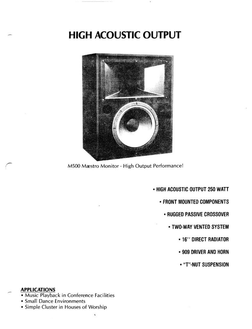
Altec Lansing M500 User manual

Altec Lansing

Altec Lansing M500 User manual

Altec Lansing A7 User manual

Altec Lansing

Altec Lansing A7 User manual

Altec Lansing 409T CEILING SPEAKER User manual

Altec Lansing

Altec Lansing 409T CEILING SPEAKER User manual

Altec Lansing JACKET H2O III User manual

Altec Lansing

Altec Lansing JACKET H2O III User manual

Altec Lansing LF SPEAKER - REPAIR User manual

Altec Lansing

Altec Lansing LF SPEAKER - REPAIR User manual

Altec Lansing BABY BOOM User manual

Altec Lansing

Altec Lansing BABY BOOM User manual

Altec Lansing 407-8A User manual

Altec Lansing

Altec Lansing 407-8A User manual

Altec Lansing ALT-T1500-PK Thunder User manual

Altec Lansing

Altec Lansing ALT-T1500-PK Thunder User manual

Altec Lansing DTS152A-F LF SPEAKER SYSTEM User manual

Altec Lansing

Altec Lansing DTS152A-F LF SPEAKER SYSTEM User manual

Altec Lansing 291-16K HF DRIVER User manual

Altec Lansing

Altec Lansing 291-16K HF DRIVER User manual

Altec Lansing 3184 LF SPEAKER User manual

Altec Lansing

Altec Lansing 3184 LF SPEAKER User manual

Altec Lansing Cone 405A User manual

Altec Lansing

Altec Lansing Cone 405A User manual

Altec Lansing AM9872 SIGNAL PROCESSING User manual

Altec Lansing

Altec Lansing AM9872 SIGNAL PROCESSING User manual

Altec Lansing SOLO MOTION User manual

Altec Lansing

Altec Lansing SOLO MOTION User manual

Popular Speakers manuals by other brands

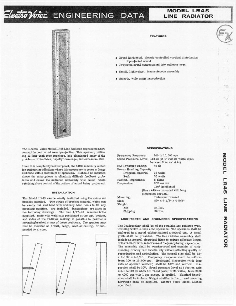
Electro-Voice LR4S engineering data

Electro-Voice

Electro-Voice LR4S engineering data

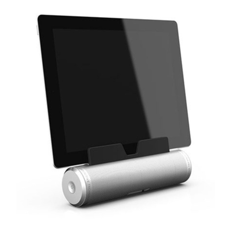
Definitive Technology Sound Cylinder user guide

Definitive Technology

Definitive Technology Sound Cylinder user guide

AudioSource LS545 user manual

AudioSource

AudioSource LS545 user manual

Paso C402-T Instructions for use

Paso

Paso C402-T Instructions for use

Kenwood KFC-1072 Servise manual

Kenwood

Kenwood KFC-1072 Servise manual

Peavey ProSys 112 user guide

Peavey

Peavey ProSys 112 user guide

JBL Control Contractor 60 Series installation instructions

JBL

JBL Control Contractor 60 Series installation instructions

Aura STORM-8 owner's manual

Aura

Aura STORM-8 owner's manual

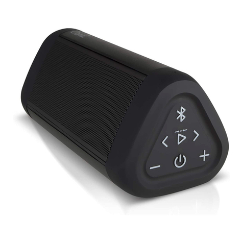
Oontz ANGLE 3 PLUS quick start guide

Oontz

Oontz ANGLE 3 PLUS quick start guide

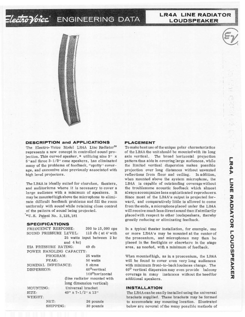
Electro-Voice LR4A engineering data

Electro-Voice

Electro-Voice LR4A engineering data

Rave RK-650-ICA-B owner's manual

Rave

Rave RK-650-ICA-B owner's manual

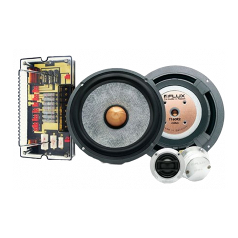
Flux Reference Series installation manual

Flux

Flux Reference Series installation manual

Lanzar AQAWBS64BK installation manual

Lanzar

Lanzar AQAWBS64BK installation manual

DAPAudio DCS-6230 manual

DAPAudio

DAPAudio DCS-6230 manual

Aluratek ABS03F quick start guide

Aluratek

Aluratek ABS03F quick start guide

Kenwood KES-5A instruction manual

Kenwood

Kenwood KES-5A instruction manual

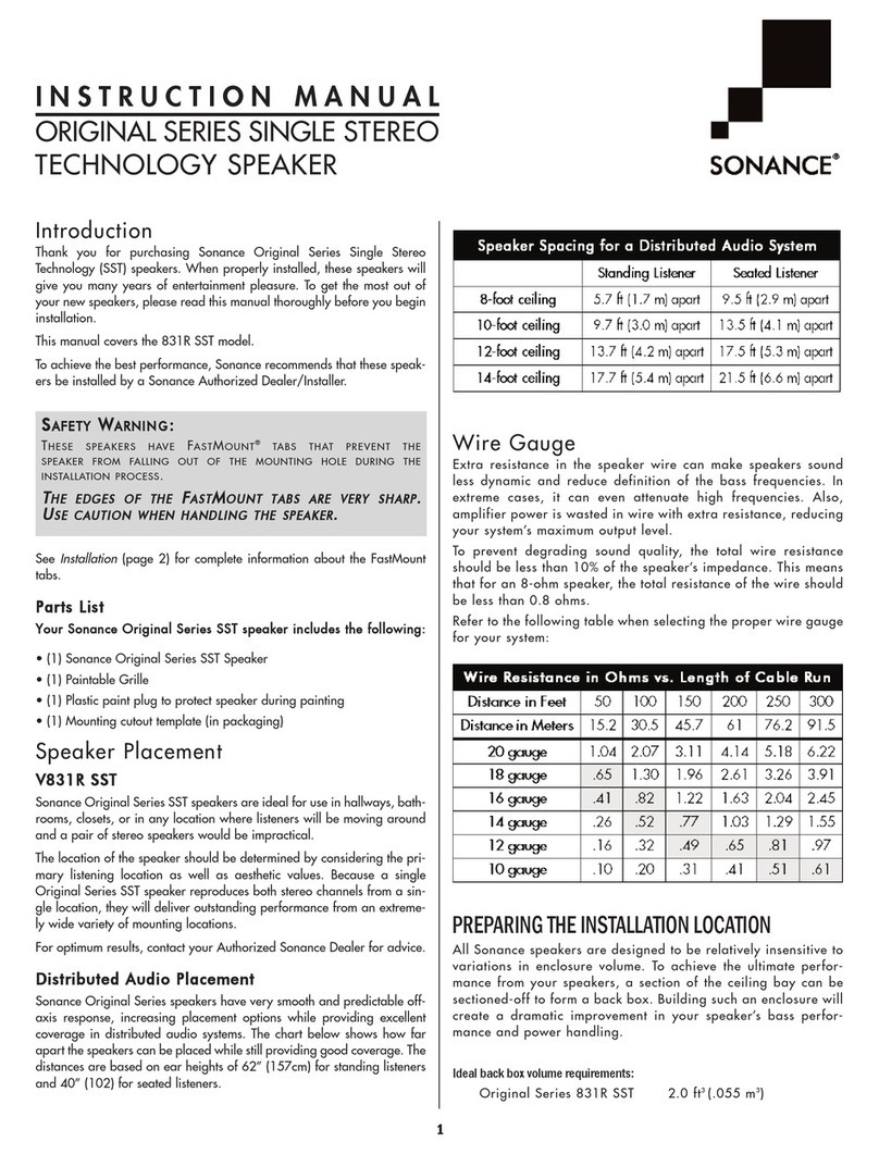
Sonance ORIGINAL SERIES instruction manual

Sonance

Sonance ORIGINAL SERIES instruction manual

Empire S-5000 user manual

Empire

Empire S-5000 user manual

manuals.online logo
manuals.online logoBrands
  • About & Mission
  • Contact us
  • Privacy Policy
  • Terms and Conditions

Copyright 2025 Manuals.Online. All Rights Reserved.

FREQUENCY RESPONSE 1, 2
40 Hz – 20 kHz
USABLE LOW FREQUENCY LIMIT (-10 dB) 1, 2
40 Hz
SENSITIVITY 3
98.5 dB SPL
POWER HANDLING 4
75 W continuous; 300 W peak
PEAK OUTPUT (1 m) 5
123 dB SPL
COVERAGE ANGLES 6
60º (horizontal) x 40º (vertical)
DIRECTIVITY FACTOR, Q 6
15.67
DIRECTIVITY INDEX, DI 6
11.95 dB
TRANSDUCER COMPONENTS
LF: 1 x 15 in., high efficiency, low frequency driver
HF: 1 x 1.0 in., compression driver and MantarayTM horn
IMPEDANCE 7
Nominal: 8.0 Ohms
Minimum: 8.5 Ohms at 12 kHz
CROSSOVER FREQUENCY
Passive LF - HF: 1,500 Hz
HARMONIC DISTORTION 8
THD: 1.25%
INPUT CONNECTIONS
2 x 2 position barrier strip with 0.25 in.
blade type terminals
FINISH
Dark gray enamel
REPLACEMENT HF DIAPHRAGM ASSEMBLY
34647
REPLACEMENT LF CONE KIT
R-604-8L
DIMENSIONS
Outside Diameter: 16.0 in. (406 mm)
Depth: 8.82 in. (224 mm)
Bolt Circle Diameter: 15 in. (381 mm)
Cut-out Diameter: 14.125 in. (359 mm)
WEIGHT
Net: 34.0 lbs. (15.4 kg), includes network
Shipping: 42.0 lbs. (19.1 kg), includes network
604-8L – THEILE-SMALL PARAMETERS
Re:6.4 Ohms
fS:28.5 Hz
VAS:412.86 liters (14.58 ft.3)
QTS:0.20
QES:0.21
QMS:7.5
VD:314.6 cm3(19.2 in.3)
η0:4.3%
Xmax:3.8mm (0.15 in.)
604-8L
15” Duplex®Studio Monitor Component
FEATURES - THE ALTEC LANSING DIFFERENCE
• High Fidelity
• Superior Efficiency
• Accurate Low Frequency Reproduction
• Dual Magnet Construction
• High Performance 75W AES / 300 W Peak Power Handling
• 1,500 Hz Dividing Network, with Dual Equalization System
GENERAL PRODUCT DESCRIPTION
Altec Lansing’s 604 loudspeaker-based systems are probably the most
famous broadcast studio and recording studio monitors of all time. For
over a quarter of a century, the 604 was employed by more studios than
all other monitor systems combined. The 604 approaches transparent
sound reproduction more than any other transducer. As one well-known
engineer stated, “When my eyes were closed, the original performance
was experienced as though it was not an electromechanical
reproduction.” The 604 is known worldwide as the original point source
standard by which other monitors are referenced. Two of the audio
industry’s highest compliments were bestowed to this loudspeaker:
• Doug and Sherwood Sax developed a special dividing network for 604-
based monitors used in over 800 of the world’s most prestigious studios.
• A major loudspeaker manufacturer used the Altec Lansing 604 as
original equipment for one of this competitor’s most famous studio
monitors.
Today’s marketplace boasts many “digital-ready” loudspeaker systems.
Most manufacturers suggest that only their newest models can manage
the dynamics presented through the digital medium. Nothing could be
further from the truth with Altec Lansing’s 604. Whether a vintage
model, or our newest model, the 604-8L, the digital medium only
improves the performance of the 604. In fact, the 604 makes “digital”
sound better.
The Altec Lansing 604-8L includes a two-way loudspeaker and a dividing
network. This Duplex®loudspeaker features a 15 in. (381 mm), low
frequency cone and a 1 in. (25 mm), high frequency compression driver.
Both are mounted to a single 16 in. (406 mm) diameter frame. The dual
magnet construction allows each driver to be structurally, magnetically,
electrically, and mechanically independent of the other.
The 604-8L utilizes a dual-section dividing network with dual
equalization (mid and high frequency). The division is centered at
1,500Hz and provides 12dB/octave of attenuation for the low
frequencies and 18dB/octave of attenuation for the high frequencies.
The low frequency cone driver features a 3.0 in. (76 mm) diameter, edge-
wound, copper-ribbon voice-coil and a 5.6 lbs. (2.54 kg) ferrite magnet -
producing a gap flux density of 1.3 T. The high frequency compression
driver features a 1.75 in. (45 mm) diameter, edge-wound, aluminum-
1000 W. Wilshire Blvd., Suite 362 • Oklahoma City, Oklahoma 73116 • Phone: 1-405-848-3108 • Fax: 1-405-848-3217 • www.altecpro.com
ribbon voice-coil and a 2.5 lbs. (1.13 kg) ferrite magnet - producing
a gap flux density of 1.6 T. The high frequency driver is channeled
through the low frequency magnetic structure and coupled to a 60º
x 40º MantarayTM constant-directivity horn that provides tight control
of frequencies above 1,500 Hz.
The 604-8L provides high acoustic output level capability while
maintaining smooth response, wide bandwidth and constant-
directivity control of the critical mid and high frequencies.
DIVIDING NETWORK INSTALLATION
The dividing network is designed to be mounted from the inside
of the speaker cabinet to a surface that is at least 0.75 in. (19 mm)
thick. Therefore, a 7.25 in. (184 mm) wide x 5 in. (127 mm) high
cutout is required on one of the speaker cabinet’s walls. Be sure
to locate this cutout where there is adequate clearance – 3 in. (76
mm) on each side of the cutout, 2 in. (51 mm) on both the top
and bottom, and at least 3 in. (76 mm) behind the cabinet wall
where the dividing network is to be mounted. Observing polarity,
connect the low frequency driver terminals to the “W” wires, and
connect the high frequency driver terminals to the “T” wires. We
recommend placing a 6.1 in. (155 mm) section of EVA foam tape,
1 in. (25 mm) wide, 0.04 in. (1 mm) thick, along the edge of both
sides of the cutout (adhesive side of the tape placed against the
inside surface of the cabinet). We also recommend placing a 7.25
in. (184 mm) section of EVA foam tape, 1 in. (25 mm) wide, 0.04
in. (1 mm) thick, along the edge of both the top and bottom of
the cutout (adhesive side of the tape placed against the inside
surface of the cabinet). Centering the HF EQ and MF EQ controls,
the input terminal, and the Altec Lansing logo in the cutout
window, firmly press the front of the dividing network plate to
the inside of the speaker cabinet wall. Using 4 each #8 x 0.5 in.
(13 mm), pan-head wood screws (preferably with a type 17 point),
secure the dividing network to the inside of the speaker cabinet
wall.
ARCHITECT’S AND ENGINEER’S SPECIFICATIONS
The loudspeaker shall be a multi-purpose, combination 15 inch
(381 mm) low frequency cone driver and one-inch (25 mm) high
frequency compression driver. The high frequency compression
driver shall be coupled to a MantarayTM constant-directivity horn.
The dividing network shall be a dual-section, 12dB/octave slope
low pass and 18dB/octave slope high pass with an electro-acoustic
crossover frequency of 1,500 Hz and dual equalization (mid and
high frequency) controls. The Duplex®loudspeaker shall have an
operating bandwidth of 40 Hz to 20 kHz with a sensitivity of 98.5
dB when measured at a distance of one meter. The power
handling capability shall be 75 watts AES (300 W peak). The
nominal impedance shall be 8 Ohms with a minimum impedance
of 8.5 Ohms at 12 kHz. The Duplex®loudspeaker shall have
nominal coverage angles of 60 degrees in the horizontal plane
and 40 degrees in the vertical plane. The Duplex®loudspeaker
shall have dimensions of 16.0 in. (406 mm) in diameter and 8.82
in. (224 mm) in depth, and shall weigh 34.0 lbs. (15.4 kg)
(including the dividing network). The Duplex®loudspeaker shall
be the Altec Lansing model 604-8L.
FREQUENCY RESPONSE
As we are continually striving to improve Altec Lansing products, specifications are subject to change without notice.
Please visit www.altecpro.com for the latest information on Altec Lansing Professional products.
1 The frequency response of the loudspeaker is measured at a distance of no less than 3 meters to obtain full range data. The level is then corrected to be
equivalent to a 2.83 V 1 m measurement. A near field measurement of the loudspeaker is performed for frequencies below 500 Hz. This data is then combined
with the full range measurement to give an accurate composite frequency response curve.
2 The limits of the frequency response are referenced to -10 dB of the loudspeaker’s rated sensitivity in a 4 ft.3vented enclosure.
3 The sensitivity of the loudspeaker is the log based average SPL taken over the intended bandwidth of operation for the loudspeaker with a 2.83 V swept sine
stimulus. The data is measured and level corrected in a manner consistent with note 1.
4 The power handling capacity of the loudspeaker is tested using a full range form of AES Standard 2-1984. The test stimulus is band limited (40 Hz – 16 kHz) pink
noise with a 6 dB crest factor. The applied RMS voltage is determined using the minimum impedance of the loudspeaker. The amplifier used to drive the
loudspeaker has a minimum operating headroom of 6 dB referenced to the RMS voltage.
5 The peak output level of the loudspeaker is calculated based on the sensitivity and the peak power handling capabilities of the loudspeaker.
6 The coverage angles for the loudspeaker are taken as the -6 dB points of the directivity response and averaged from 500 Hz – 16 kHz.
7 The minimum impedance of the loudspeaker is taken over its intended band of operation.
8 The distortion measurements of the loudspeaker are performed at a distance of 1 m with RMS input voltages corresponding to 10% of the loudspeaker’s rated
power handling, calculated using minimum loudspeaker impedance. The distortion percentages are log based averages from 300 Hz – 3 kHz.
VISIT WWW.ALTECPRO.COM FOR
• Authorized EASE data on all Altec Lansing Professional loudspeakers
• Specification sheets in .pdf format. Download page 1 of the specification sheet for you submittals.
• One paragraph A&E Specifications in .doc format
SPECIFICATION NOTES
AW1075 REV03
© 2003 Altec Lansing Professional
1000 W. Wilshire Blvd., Suite 362
Oklahoma City, Oklahoma 73116
Phone: 1-405-848-3108 • Fax: 1-405-848-3217
Web: www.altecpro.com • Email: [email protected]
BEAMWIDTH