Altinex MUSE MU600-001 User manual

MUSE™: HDMI+POWER+IR Receiver User’s Guide
400-0598-002
Welcome!
Everyone at Altinex greatly appreciates your purchase of the MUSE
Receiver. We are confident you will find it reliable and simple to use. If
you need support, please do not hesitate to call us at 714-990-2300.
We are committed to developing unique and state of the art Signal
Management Solutions®for demanding audiovisual installations. Welcome
to the Altinex family of satisfied customers around the world.
1. Precautions and Safety Warnings
Please read this manual entirely before using your MU500-112 Receiver.
You can download a full version of this manual on www.altinex.com.
These safety instructions are to ensure the reliable operation of your
MU500-112 Receiver and to prevent fire and shock hazards. Please read
them carefully and heed all warnings.
1.1 General
The MU500-112 Receiver does not contain any user serviceable
parts. Only qualified ALTINEX service personnel may perform
product service.
The MU500-112 Receiver is safety tested and is ETL listed.
The MU500-112 Receiver incorporates a proprietary technology for
transmission of display power and video over a low voltage CAT-6
cable.
1.2 Installation Precautions
To prevent fire or shock, do not expose this unit to water or
moisture. Do not place the MUSE Receiver in direct sunlight, near
heaters or heat-radiating appliances, or near any liquid. Exposure to
direct sunlight, smoke, or steam can harm internal components.
Handle the MU500-112 Receiver carefully. Dropping or jarring can
cause damage.
Do not pull any cables that are attached to the MU500-112 Receiver.
For optimal safety when disassembling the MUSE Receiver, first
unplug the power cord, which supplies power to both the
transmitter and receiver, from the AC outlet.
1.3 Cleaning
Clean the MU500-112 Receiver only with a dry cloth. Never use
strong detergents or solvents such as alcohol or thinner. Do not use
a wet cloth or water to clean.
1.4 FCC Notice
This device complies with Part 15 of the FCC Rules. Operation is
subject to the following two conditions: (1) This device may not
cause harmful interference, and (2) this device must accept any
interference received, including interference that may cause
undesired operation.
This equipment has been tested and found to comply with the limits
for a Class A digital device, pursuant to Part 15 of the FCC Rules.
These limits are designed to provide reasonable protection against
harmful interference when the equipment is operated in a
commercial environment. This equipment generates, uses, and can
radiate radio frequency energy and, if not installed and used in
accordance with the instructions found herein, may cause harmful
interference to radio communications. Operation of this equipment
in a residential area is likely to cause harmful interference in which
case the user will be required to correct the interference at his own
expense.
Any changes or modifications to the unit not expressly approved by
ALTINEX, Inc. could void the user’s authority to operate the
equipment.
2. Installation Procedures
Note: The CAT-6 type cable is a critical component to the functionality of the unit. Use only the recommended cables for optimum performance. See the
minimum cable requirements on the technical specifications page.
Step 1. For detailed information, download and read the entire manual from (www.altinex.com).
Step 2. Connect the MU500-112 Receiver to the monitor using a standard HDMI cable. Plug the display power cord in to the AC receptacle on the MU500-
112 Receiver.
Step 3. Connect the MU500-112 Receiver to the MU400-111 Transmitter using terminated, unshielded CAT-6 cable.
Required cable gauge is AWG23 to achieve full power. (Note: Use MU400-111 Transmitter with Altinex
MU500-112 Receiver only)
Step 4. Apply AC power to the MU400-111 Transmitter. As soon as the transmitter detects the receiver, it will allow
power to be transmitted to the receiver, followed by the HDMI signal. It may take several minutes to monitor
power up and see the image displayed on the monitor.
Step 5. Connect the IR receiver to the MUSE Receiver; place the eye near the front of the display and secure with the adhesive provided.
Step 6. The MUSE Receiver is now ready for operation.
3. Limited Warranty/Return Policies
Please visit the ALTINEX website at www.altinex.com for details on warranty and return policies. In the case of a unit needing repair, please fill out the RMA
(return material authorization) form located on the bottom left hand corner of the Altinex homepage. Once filled out, please email the form to

MUSE™: HDMI+POWER+IR Receiver User’s Guide
400-0598-002
Willkommen!
Wir alle hier bei Altinex schätzen Ihren Kauf des MUSE Receivers. Wir sind
überzeugt, dass Sie ihn sowohl zuverlässig als auch benutzerfreundlich finden
werden. Wenn Sie Hilfe benötigen, rufen Sie uns gerne jederzeit an unter
714-990-2300.
Wir widmen uns der Entwicklung einmaliger, moderner Signal Management
Solutions®für anspruchsvolle audiovisuelle Installationen. Willkommen bei
der Altinex Familie zufriedener Kunden auf der ganzen Welt.
1. Sicherheits- und Warnhinweise
Bitte lesen Sie sich diese Anleitung ganz durch, bevor Sie Ihren MU500-112
Receiver verwenden. Sie können die Vollversion dieser Anleitung auf
www.altinex.com herunterladen. Diese Sicherheitsanweisungen sollen den
zuverlässigen Betrieb Ihres MU500-112 Receiver gewährleisten und Brand-
sowie Stromschlaggefahren vermeiden. Bitte lesen Sie sie sorgfältig durch und
beachten Sie alle Warnhinweise.
1.1 Allgemeines
Der MU500-112 Receiver enthält keine wartbaren Teile.
Wartungsarbeiten am Produkt dürfen nur von qualifiziertem ALTINEX
Kundendienstpersonal durchgeführt werden.
Der MU500-112 Receiver wurde auf Sicherheit getestet und trägt die
ETL-Kennzeichnung.
Der MU500-112 Receiver umfasst geschützte Techniken für die
Übertragung von Anzeigestrom und Video über ein CAT-6-
Niederspannungskabel.
1.2 Vorsichtsmaßnahmen bei der Installation
Um Brand- und Stromschlaggefahr abzuwenden, setzen Sie dieses Gerät
niemals Wasser oder Feuchtigkeit aus. Setzen Sie den MUSE Receiver
nicht direktem Sonnenlicht, Heizkörpern oder
hitzeabstrahlenden -Geräten aus, noch sollte er in der Nähe von
Flüssigkeiten aufgestellt werden. Durch direktes Sonnenlicht, Rauch
oder Dampf können die inneren Komponenten beschädigt werden.
Behandeln Sie den MU500-112 Receiver mit Sorgfalt. Stürze oder
Rütteln können zu inneren oder äußeren Schäden führen.
Ziehen Sie nicht an den Kabeln, die am MU500-112 Receiver
angebracht sind.
Für optimale Sicherheit sollte nur dann Strom angelegt werden, wenn
das System vollständig verkabelt ist.
1.3 Reinigung
Reinigen Sie den MU500-112 Receiver nur mit einem trockenen Tuch.
Verwenden Sie keine Reiniger oder Lösungsmittel wie z.B. Alkohol
oder Verdünnungsmittel. Verwenden Sie kein nasses Tuch oder Wasser
zur Reinigung.
1.4 FCC Hinweis
Dieses Gerät entspricht Teil 15 der FCC Regelungen. Betrieb unterliegt
den folgenden beiden Bedingungen: 1. Dieses Gerät darf keine
gefährlichen Störungen verursachen und 2. Dieses Gerät muss mögliche
empfangene Funkstörungen und dadurch verursachte
Funktionsstörungen akzeptieren.
Diese Anlage wurde getestet und unterliegt den gemäß Teil 15 der
FCC-Vorschriften für digitale Geräte der Klasse A festgelegten
Beschränkungen. Diese Grenzwerte sind so ausgelegt, dass sie in
gewerblichen Bereichen einen ausreichenden Schutz vor schädlichen
Störungen bieten. Dieses Gerät erzeugt, verwendet und emittiert
möglicherweise Energie auf Funkfrequenzen, die bei unsachgemäßer
Installation und Verwendung oder unter Nichtbeachtung der
Anweisungen Störungen des Funkverkehrs verursachen kann. Der
Betrieb des Geräts in einem Wohnbereich zieht wahrscheinlich
negative Störungen nach sich, die der Benutzer auf eigene Kosten zu
korrigieren hat.
Veränderungen oder Modifikationen an diesem Gerät, die nicht
ausdrücklich von ALTINEX genehmigt wurden, können bewirken, dass
der Benutzer das Gerät nicht mehr betreiben darf.
2. Installationsverfahren
Hinweis: Das CAT-6 Kabel ist ein wichtiger Bestandteil für die Funktionalität des Geräts. Verwenden Sie ausschließlich empfohlene Kabel für optimale
Leistung. Die Kabelanforderungen finden Sie auf der Seite für technische Angaben.
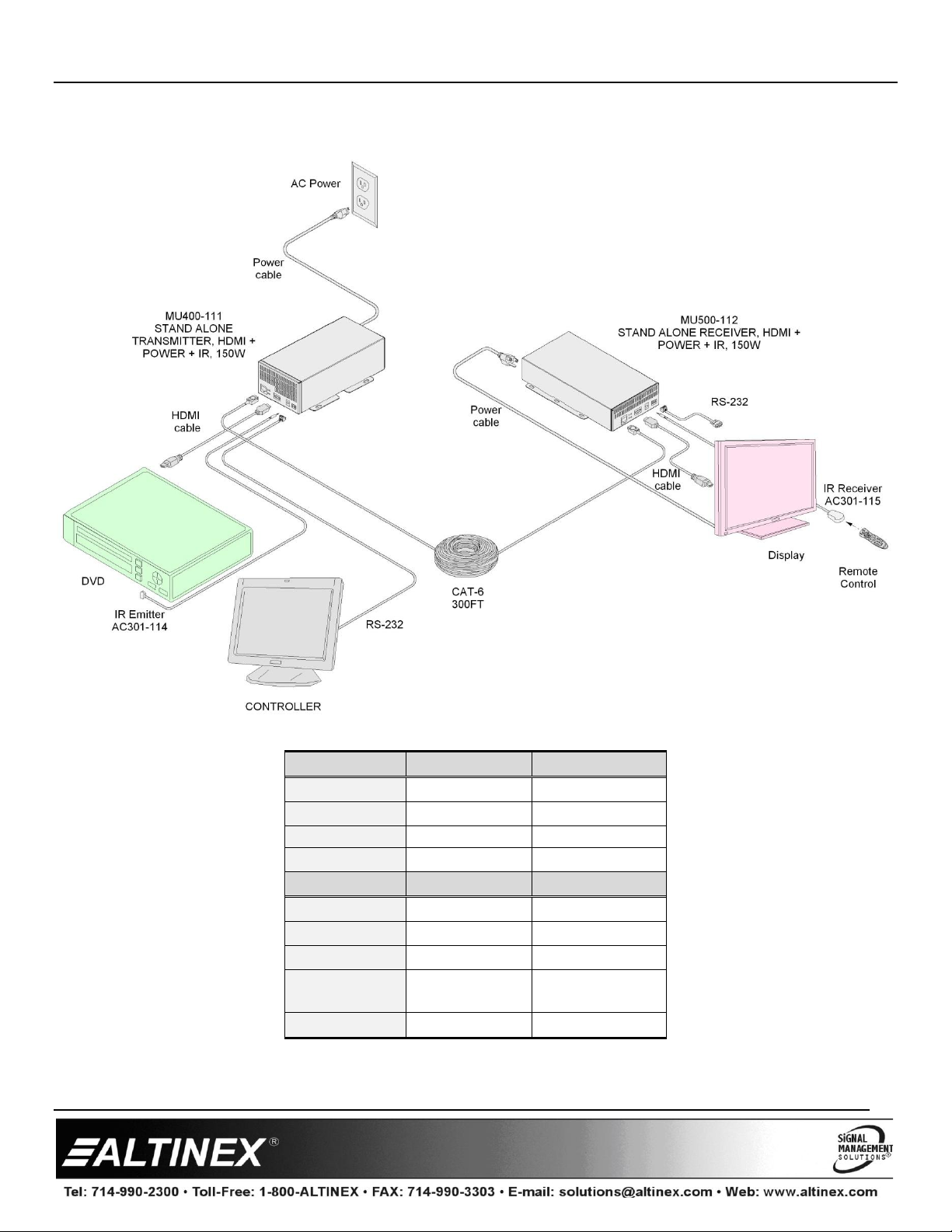
1. Schritt: Für Einzelheiten laden Sie die gesamte Anleitung unter www.altinex.com herunter und lesen Sie durch.
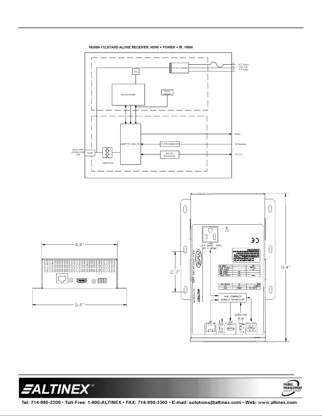
2. Schritt: Verbinden Sie die HDMI-Quelle mit dem Anschluss des MU500-112 Receivers mit einem
herkömmlichen HDMI-Kabel. Stecken Sie das Stromkabel des Bildschirms in die AC-Buchse am
MU500-112 Receiver.
3. Schritt: Verbinden Sie den MU500-112 Receiver mit einem begrenzten, ungeschirmten CAT-6-Kabel am
MU500-111 Transmitter. Die benötigte Kabelstärke für vollständige Leistung ist AWG23. (Hinweis:
Verwenden Sie nur einen MU400-111 Transmitter mit dem Altinex MU500-112 Receiver)
4. Schritt: Schließen Sie den MU400-111 Transmitter an eine Wechselstromquelle an. Sobald der Transmitter den Receiver erkennt, wird Strom an den Receiver
übertragen, gefolgt vom HDMI-Signal. Es kann einige Minuten dauern, bis der Bildschirm startet und ein Bild zu sehen ist.
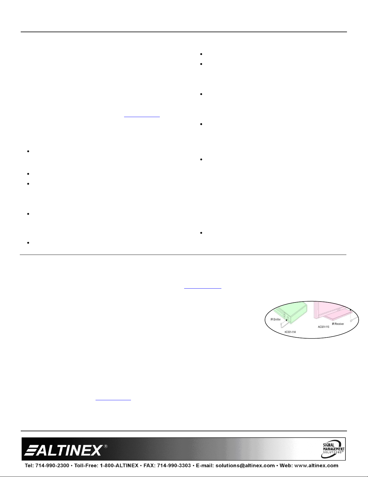
5. Schritt: Verbinden Sie den IR-Receiver mit dem MUSE Receiver; stellen Sie die Linse vor dem Bildschirm auf und befestigen sie mit dem beigefügten
Klebeband.
6. Schritt: Der MUSE Receiver ist nun betriebsbereit.
3. Garantie und Rückgaberichtlinien
Bitte besuchen Sie ALTINEX Website unter www.altinex.com und lesen Sie die Einzelheiten über Garantie- und Rückgaberichtlinien durch. Wenn ein Gerät
repariert werden muss, füllen Sie bitte das RMA (Return Material Authorization) Formular unten links auf der Altinex Homepage aus. Dann senden Sie das
ausgefüllte Formular via E-Mail an support@altinex.com.

MU500-112 User’s Guide
400-0598-002
4. About Your MUSE Receiver
Deliver Power, HDMI, and control 300 ft. (91 m) over a single cable
Power 42”-52” displays with up to 150 W of clean power
Bidirectional pass through RS232 communication (9600 baud rate)
Gives integrators greater control over their AV projects
HDMI** and HDCP Compliant (see details)
Transmit IR signals from receiver (far end) to transmitter (near side)
Easy low voltage installation is safe and reliable
The Muse line of products allow users to transmit HDMI video, display AC power, and IR signals up to 300ft (91m) over a single
unshielded CAT-6 cable. The Muse is powerful enough to power a 150 watt LCD display and can extend power up to 300 ft.
away from a signal and power source. The Muse is fully compliant with HDMI and HDCP standards. Advanced features of the
MU500-112 Receiver provide a safe and reliable way of sending both signal and power over a single unshielded CAT-6 cable as
well as RS232 and infrared control of third party devices. Simplicity of installation makes it a “no brainer” for your next AV
system design.
Output of the transmitter unit is monitored for power consumption and when power is exceeded, the output is turned off to
protect all components. The MUSE can power a 46” to 52” display with a maximum continuous power consumption of 150 watts.
The MU500-112 provides constant power and voltage to the display. When the cable length increases, the system automatically
adjusts itself to provide the maximum possible power to the display. Since CAT type cables have resistance associated with them,
care must be taken to use the smallest possible cable length to maximize power transfer.
The MU500-112 Receiver has many advanced features to safely transmit power to a display. These features include: current
monitoring, auto shutdown and an auto receiver detector. Each unit has a durable metal enclosure with built-in ball bearing
cooling fans to provide years of trouble free operation. Every Muse product comes with a 3 year ALTINEX Warranty.
The transmitter-receiver combination has a built in IR channel that allows s IR signals to be sent from the receiver (display side)
back to the transmitter (source side), to control AV equipment. This feature simplifies setup and provides convenience when AV
equipment is hidden out of sight.
** The HDMI video source MUST support clock stretchingon the Clock line.

MU500-112 User’s Guide
400-0598-002 6
4. About Your MUSE Receiver
Strom, HDMI und 91m-Steuerung über ein einzelnes Kabel.
Versorgen Sie 42-52 Zoll Bildschirme mit bis zu 150 W Ökostrom
Bidirektionaler Durchgang über RS232 Kommunikation (9600 Baudrate)
Bietet Integratoren mehr Kontrolle über ihre AV-Projekte
HDMI**- und HDCP-konform (siehe Details)
Senden Sie IR-Signale vom Receiver (Gegenstelle) an den Transmitter
(Nahseite)
Einfache Niederstrominstallation ist sicher und zuverlässig
Mit der Muse Produktreihe kann der Benutzer HDMI-Video senden und Wechselstrom und IR-Signale 91m weit über ein
einziges ungeschirmtes CAT-6-Kabel anzeigen. Muse ist stark genug, um eine 150 Watt LCD-Anzeige zu betreiben und die
Leistung 91m von der Signal- und Stromquelle erweitern. Muse entspricht allen HDMI- und HDCP-Standards. Die erweiterten
Funktionen des MU500-112 Receiver bieten eine sichere und zuverlässige Art, Signale und Strom über ein einziges,
ungeschirmtes CAT-6-Kabel sowie RS232 und Infrarot-Steuerung von Fremdgeräten zu senden. Die einfache Installation macht
Ihre nächstes AV-Systemdesign "idiotensicher".
Der Stromverbrauche an der Ausgabe des Transmitters wird überwacht und wenn die Leistung überschritten wird, wird die
Ausgabe zum Schutz aller Komponenten abgeschaltet. MUSE kann einen 46-52 Zoll-Bildschirm mit maximalem Stromverbrauch
von 150 Watt betreiben. Der MU500-112 Receiver liefert kontinuierlich Strom und Spannung an den Bildschirm. Wenn die
Kabellänge zunimmt, stellt sich das System automatisch ein, um der Anzeige die höchstmögliche Leistung zu bieten. Da CAT-
Kabel Widerstand leisten, muss sorgfältig darauf geachtet werden, dass das Kabel so kurz wie möglich gehalten wird, um die
Stromübertragung zu maximieren.
Der MU500-112 Receiver besitzt viele fortschrittliche Funktionen zur sicheren Stromübertragung an den Bildschirm. Diese
Funktionen sind u.a.: Spannungsüberwachung, automatische Abschaltung und ein Auto-Receiver-Detektor. Jedes Gerät verfügt
über ein haltbares Metallgehäuse mit eingebauten, kugelgelagerten Ventilatoren, um Jahre störungsfreien Betriebs zu
gewährleisten. Jedes Muse Produkt wird von einer 3-Jahre ALTINEX Garantie begleitet.
Die Kombination aus Transmitter und Receiver besitzt einen eingebauten IR-Kanal, mit dessen Hilfe IR-Signale vom Receiver
(Anzeigeseite) zurück an den Transmitter (Quellenseite) gesendet werden können, um die AV-Anlage zu steuern. Diese
Funktion vereinfacht das Setup und ist praktisch, wenn AV-Anlagen außer Sicht versteckt sind.
** Die HDMI-Videoquelle MUSS Taktdehnung auf der Taktleitung unterstützen
on the Clock line.

MU500-112 User’s Guide
400-0598-002
CONTENTS
English
Power Calculations 6-7
Technical Specifications 8
Application Diagram 9
Internal View/ Dimension Diagrams 10
Recommended Components/ Operation 11
Troubleshooting Guide 12
German
Power Calculations 13-14
Technical Specifications 15
Application Diagram 16
Internal View/ Dimension Diagrams 17
Recommended Components/ Operation 18
Troubleshooting Guide 19

MU500-112 User’s Guide
400-0598-002 6
Available Power
Distance (ft)
Available Power
Available Surge
Power (10 Seconds)
AWG23
25
150
254
50
150
249
75
150
244
100
150
238
125
150
233
150
150
228
175
148
223
200
146
218
225
144
213
250
142
208
275
140
202
300
138
197
Available Power Calculations (Example Calculations for 300ft Cable)
1. Resistance
Resistance of a single strand of CAT-6 Cable: 20Ω per 1000ft
Resistance of the 4 strands in a CAT-6 Cable: 5Ω per 1000ft
Example:
(5Ω x 300ft x 2)/1000ft = 3Ω [NOTE: x2 because cable travels 2 ways (from inverter to receiver and vice versa)]

MU500-112 User’s Guide
400-0598-002 7
2. Voltage
Current across CAT-6 Cable: 2.9A (max)
Inverter Voltage: 60V
Current x Resistance = Voltage Drop
Example:
2.9A x 3Ω = 9V
Inverter Voltage –Voltage Drop = Voltage on Inverter
Example:
60V –9V = 51V
3. Power
Voltage on Inverter x Current = Power to Receiver
Example:
51V x 2.9A = 148W
Power to Receiver - Power Used by Receiver = Available Power
Example:
148W –10W = 138W
Available Surge Power Calculations (Example Calculations for 300ft Cable)
1. Voltage
Surge Current: 4.5 A
Surge Current x Resistance = Surge Voltage Drop
Example:
4.5A x 3Ω = 14V
Inverter Voltage –Surge Voltage Drop = Surge Voltage on Inverter
Example:
60V –14V = 46V
2. Power
Surge Voltage x Surge Current = Surge Power
Example:
46V x 4.5A = 207W
Surge Power to Receiver –Power Used by Receiver = Available Surge Power
Example:
207W –10W = 197W

MU500-112 User’s Guide
400-0598-002 8
5. Technical Specifications
Specifications are subject to change. See www.altinex.com for up-to-date information.
Features/Description
Specification
MU500-112 Receiver
Input Connectors
HDMI + Power
RJ-45 F (1)
IR Receiver
3.5 mm F (1)
Output Connectors
AC Power
NEMA 5-15R (1)
RS-232 Connector
3 POS TB (1)
Compatibility
Signal Types
HDMI
HD TV Resolution
480p to 1080p
Computer Resolution
1920 x 180 at 60Hz
Use with
MU400-111
Optional Accessories
IR Receiver
AC301-115
Table 1. MUSE Receiver General
Mechanical
Specification
Material
0.031” Steel
Color
Clear Zinc
MTBF (calc.)
38,000 hrs.
Receiver: Height
1.7 in (43 mm)
Width
(no mounting ears)
4.3 in (109 mm)
Depth
8.7 in (221 mm)
Weight
2.0 lb. (0.9 kg)
T° Operating
10°C-50°C
T° Maximum
75°C
Humidity
90% non-condensing
Table 2. MUSE Receiver Mechanical
Electrical
Specification
Video
HDBT Input
RJ-45
Video Output
HDMI
Power
Receiver (from MU400-11
Transmitter)
172 W (max)
Receiver to load power
150 W (max)
Receiver Output Voltage
120 VAC (sine wave)
Table 3. MUSE Receiver Electrical
CAT-6 Cable
Minimum Cable
Specifications
Conductor
material/size/quantity:
Bare Copper/ 23 AWG / 8
Conductor Construction:
Solid+ Unshielded
Color code:
Per TIA/EIA 568-B
Flammability Rating:
IEC 60332-1, UL 1581
VW-1
Frequency Range:
1~550 MHz
Voltage:
300 V
Operating Temperature:
–20 °C to +60 °C
HDBT Certified
UTP, CAT-6 or CAT6a
Recommended cable type
See Diagram 6
Table 4. CAT-6 Cable Minimum Specifications

MU500-112 User’s Guide
400-0598-002 9
6. Application Diagrams
Diagram 1: Typical Setup
Table 5: Status of MU500-112 Receiver
TX STATUS
POWER
PAIR
NORMAL
ON
ON
IDLE
ON
SLOW BLINKING
FAULT
FAST BLINKING
FAST BLINKING
VIDEO STATUS
LINK
VIDEO
LINK ACTIVE
ON
LINK FAILED
OFF
HDCP ACTIVE
ON
HDCP
INACTIVE
BLINKING
No video
OFF

MU500-112 User’s Guide
400-0598-002 10
Diagram 2: Receiver Internal View
Diagram 3: Receiver Dimensions

MU500-112 User’s Guide
400-0598-002 11
Recommended Components
7. Operation
The MU500-112 Receiver requires no adjustments for performance. Once set-up, the MU500-112 Receiver will work
trouble-free without user intervention. For technical support please call 1-800-ALTINEX(258-4639).
There are few things that need to be done right to assure trouble-free operation:
1. Assure that the correct cable and connector are used. Use the recommended cables and connectors as they were tested
with the MUSE products. Patch cables should not be used with the MUSE because they do not have the current capacity
to provide sufficient power to a display. Also, patch cables attenuate HDMI signal and therefore will result in unreliable
video.
2. Terminate RJ45 connectors using proper tools. Many plastic termination tools do not have the strength to make good
termination. Use the recommended tool to avoid damaging MUSE RJ-45 connectors. In our experience, the most
damage occurs when connectors are not properly terminated.
3. Use only as much cable as needed to get from a source to display. Do not coil and leave extra cable “just in case”. Every
foot of cable takes little bit of power away from the receiver (Typically 5W per 25ft of cable). Making the cable as short
as possible maximizes the power available to the display.
4. Understand your monitor power consumption. Most monitors 42”-50” screen size can be powered by MUSE. There are
however some exceptions for monitors that have very large initial current requirements. These are typically Plasma
displays or low cost, non-Energy Star compliant displays. If you have difficulty powering up a display, adjust the settings
to Eco mode (which will maximize power consumption).
5. The MUSE can power multiple displays and other equipment. The only limitation is the initial startup current value.
This can be minimized by turning each display ON separately about 5-10 seconds apart.
6. Many monitors have a built in audio amplifier. This amplifier can consume a lot of power when set to maximum
volume. Make sure to adjust the volume to the level that will actually be used. It is not unusual for an audio amplifier to
consume 20-50W of peak power and be listed at 15W RMS power.
7. In addition to displays, the MUSE products can power any other equipment compatible with 120V outputs. This
includes lights, small motors, computers, laptops and many more accessories. Since these accessories have a smaller
initial current (compared to monitors), it will be possible to load the output of the MUSE to its limit.
8. To fully understand your monitor profile, it is advisable to purchase a low cost Watt meter that will display the power
consumption of a display. This will eliminate the hassle of trial and error when selecting the right monitor.
Supplier
Designator
Part Number
Description
Supplier Website
Firefold
Crimp tool
100004C
Modular Crimping Tool
www.firefold.com
RJ45 Connector
CAT6-RJ45-23AWG-
SOL
RJ45 Connector
www.firefold.com
CAT6 cable
1 KCMR-BLU
CAT 6 cable
www.firefold.com
CAT6 cable
CAT6-1KSOL-BLU
CAT 6 cable
www.firefold.com
Teldor
CAT6 cable
750AZ04129
CAT 6 cable
www.teldor.com

MU500-112 User’s Guide
400-0598-002 12
8. Troubleshooting Guide
MUSE
Symptom
Resolution
LEDs Are OFF
1. Make sure the MU400-111 Transmitter is plugged into a working AC outlet.
2. Disconnect the MU500-112 Receiver and verify that the LEDs show Idle mode on the
MU400-111 Transmitter. If the MU500-112 Receiver is causing the problem, the MU400-
111 Transmitter will show normal operation.
3. Verify that the cable is properly terminated. For proper pin-out, check the cable with a
cable checker.
Always Idle Mode
1. Verify the display is connected to the MUSE receiver.
2. Check the CAT-6 cable specifications. The CAT-6 cable is critical to proper operation and
power transfer.
Fault LED is ON
1. Disconnect the display from the MU500-112 Receiver and see if the problem is fixed.
2. Disconnect the MU500-112 Receiver from the MU400-111 Transmitter. If the problem is
fixed, wait 10 seconds and then reconnect the MU500-112 Receiver.
3. Reconnect the display; if the fault returns, check the display power requirements.
Note: There is sufficient power for displays rated at 150 W or less. If the display is rated
above 150 W the MUSE will not be able to power the unit. Try another display.
No Video on Display
1. Check the source and make sure there is a signal present.
2. Make sure the display is turned on.
3. Make sure the display is set to the correct HDMI input.
4. If the display is receiving power and set to the correct input, make sure the cables are
connected properly.
5. Switch the source to a lower resolution and check to see if the image is then displayed.
No Sound
1. Make sure the display/TV is not muted.
2. Set the volume on the display/TV to midrange.
3. If the source is a PC/laptop, make sure the sound is set to the HDMI output. On some
computers, this step must be done manually the first time the computer is connected to a
HDMI device.

MU500-112 User’s Guide
400-0598-002 13
Available Power
Distance (ft)
Available Power
Available Surge
Power (10 Seconds)
AWG23
25
150
254
50
150
249
75
150
244
100
150
238
125
150
233
150
150
228
175
148
223
200
146
218
225
144
213
250
142
208
275
140
202
300
138
197
Verfügbare Leistungskalkulationen (Beispielberechnung für ein 91m-Kabel)
4. Resistance
Resistance of a single strand of CAT-6 Cable: 20Ω per 1000ft
Resistance of the 4 strands in a CAT-6 Cable: 5Ω per 1000ft
Example:
(5Ω x 300ft x 2)/1000ft = 3Ω [NOTE: x2 because cable travels 2 ways (from inverter to receiver and vice versa)]

MU500-112 User’s Guide
400-0598-002 14
5. Voltage
Current across CAT-6 Cable: 2.9A (max)
Inverter Voltage: 60V
Current x Resistance = Voltage Drop
Example:
2.9A x 3Ω = 9V
Inverter Voltage –Voltage Drop = Voltage on Inverter
Example:
60V –9V = 51V
6. Power
Voltage on Inverter x Current = Power to Receiver
Example:
51V x 2.9A = 148W
Power to Receiver - Power Used by Receiver = Available Power
Example:
148W –10W = 138W
Available Surge Power Calculations (Example Calculations for 300ft Cable)
3. Voltage
Surge Current: 4.5 A
Surge Current x Resistance = Surge Voltage Drop
Example:
4.5A x 3Ω = 14V
Inverter Voltage –Surge Voltage Drop = Surge Voltage on Inverter
Example:
60V –14V = 46V
4. Power
Surge Voltage x Surge Current = Surge Power
Example:
46V x 4.5A = 207W
Surge Power to Receiver –Power Used by Receiver = Available Surge Power
Example:
207W –10W = 197W

MU500-112 User’s Guide
400-0598-002 15
5. Technical Specifications
Specifications are subject to change. See www.altinex.com for up-to-date information.
Features/Description
Specification
MU500-112 Receiver
Input Connectors
HDMI + Power
RJ-45 F (1)
IR Receiver
3.5 mm F (1)
Output Connectors
AC Power
NEMA 5-15R (1)
RS-232 Connector
3 POS TB (1)
Compatibility
Signal Types
HDMI
HD TV Resolution
480p to 1080p
Computer Resolution
1920 x 180 at 60Hz
Use with
MU400-111
Optional Accessories
IR Receiver
AC301-115
Table 1. MUSE Receiver General
Mechanical
Specification
Material
0.031” Steel
Color
Clear Zinc
MTBF (calc.)
38,000 hrs.
Receiver: Height
1.7 in (43 mm)
Width
(no mounting ears)
4.3 in (109 mm)
Depth
8.7 in (221 mm)
Weight
2.0 lb. (0.9 kg)
T° Operating
10°C-50°C
T° Maximum
75°C
Humidity
90% non-condensing
Table 2. MUSE Receiver Mechanical
Electrical
Specification
Video
HDBT Input
RJ-45
Video Output
HDMI
Power
Receiver (from MU400-11
Transmitter)
172 W (max)
Receiver to load power
150 W (max)
Receiver Output Voltage
120 VAC (sine wave)
Table 3. MUSE Receiver Electrical
CAT-6 Cable
Minimum Cable
Specifications
Conductor
material/size/quantity:
Bare Copper/ 23 AWG / 8
Conductor Construction:
Solid+ Unshielded
Color code:
Per TIA/EIA 568-B
Flammability Rating:
IEC 60332-1, UL 1581
VW-1
Frequency Range:
1~550 MHz
Voltage:
300 V
Operating Temperature:
–20 °C to +60 °C
HDBT Certified
UTP, CAT-6 or CAT6a
Recommended cable type
See Diagram 6
Table 4. CAT-6 Cable Minimum Specification

MU500-112 User’s Guide
400-0598-002 16
6. Application Diagrams
Diagram 2: Typical Setup
Table 5: Status of MU500-112 Receiver
TX STATUS
POWER
PAIR
NORMAL
ON
ON
IDLE
ON
SLOW BLINKING
FAULT
FAST BLINKING
FAST BLINKING
VIDEO STATUS
LINK
VIDEO
LINK ACTIVE
ON
LINK FAILED
OFF
HDCP ACTIVE
ON
HDCP
INACTIVE
BLINKING
No video
OFF

MU500-112 User’s Guide
400-0598-002 17
Diagram 2: Receiver Internal View
Diagram 3: Receiver Dimensions

MU500-112 User’s Guide
400-0598-002 18
Recommended Components
7. Betrieb
Der MU500-112 Receiver benötigt eine Einstellungen, um Leistung zu erbringen. Wenn er einmal eingerichtet ist, funktioniert
der MU500-112 Receiver störungsfrei und ohne Benutzer-Eingreifen. Sie erhalten technischen Support unter der Rufnummer
1-800-ALTINEX(258-4639).
Für störungsfreien Betrieb sind zuerst einige Punkte zu beachten:
1. Stellen Sie sicher, dass die richtigen Kabel und Anschlüsse verwendet werden. Verwenden Sie die empfohlenen Kabel
und Anschlüsse, da diese an MUSE-Produkten getestet wurden. Patchkabel sollten nicht mit MUSE verwendet werden,
da sie nicht die Stromleistung erbringen, um ausreichenden Strom an einen Bildschirm zu liefern. Außerdem
schwächen Patchkabel das HDMI-Signal, was wiederum zu unzuverlässiger Videoleistung führt.
2. Stellen Sie RJ45-Anschlüsse mit dem entsprechenden Termination-Werkzeug her. Viele Kunststoff-Termination-
Werkzeuge sind nicht stark genug, um eine gute Termination beizuführen. Verwenden Sie die empfohlenen
Werkzeuge, um Schäden an den MUSE RJ-45 Anschlüssen zu vermeiden. Unserer Erfahrung nach treten die meisten
Schäden auf, wenn Anschluss-Termination nicht richtig ausgeführt wurde.
3. Verwenden Sie nur die Menge Kabel, die von einer Quelle zum Bildschirm erforderlich ist. Rollen Sie übriges Kabel
nicht "für alle Fälle" auf. Jedes zusätzliche Stück Kabel nimmt Strom vom Receiver (normalerweise 5W pro 7,5m Kabel).
Halten Sie das Kabel so kurz wie möglich, um die am Bildschirm verfügbare Leistung zu maximieren.
4. Sie sollten den Stromverbrauch Ihres Bildschirms verstehen. MUSE kann die meisten 42-50 Zoll Bildschirme betreiben.
Es gibt jedoch Ausnahmen für Bildschirme mit hohen internen Stromanforderungen. Es handelt sich dabei
hauptsächlich um Plasmabildschirme oder billige Anzeigen, die nicht den Energy-Star Anforderungen entsprechen.
Wenn Sie Schwierigkeiten haben, einen Bildschirm zu starten, stellen Sie die Einstellungen auf Eco-Modus ein,
wodurch der Stromverbrauch maximiert wird.
5. MUSE kann mehrere Bildschirme und andere Geräte mit Strom versorgen. Die einzige Beschränkung ist der Wert des
Einschaltstroms. Dieser kann minimiert werden, indem jeder Bildschirm separat und 5-10 Sekunden nacheinander
eingeschaltet wird.
6. Viele Bildschirme haben eingebaute Audioverstärker. Diese Verstärker können sehr viel Strom verbrauchen, wenn Sie
auf volle Lautstärke eingestellt sind. Achten Sie darauf, dass Sie die Lautstärke auf den Wert einstellen, der tatsächlich
verwendet wird. Es ist nicht ungewöhnlich, dass ein Amplifier 20-50W Spitzenleistung verbraucht und für 15W RMS-
Strom aufgeführt ist.
7. Zusätzlich zu den Bildschirmen können MUSE-Produkte alle anderen Anlagen betreiben, die mit der 120V Ausgabe
kompatibel sind. Dazu gehören Lampen, kleine Motoren, Computer, Laptops und noch mehr Zubehör. Da dieses
Zubehör geringere Startleistung aufweist (im Vergleich zu den Bildschirmen), kann die Ausgabe von MUSE bis zum
Limit ausgelastet werden.
8. Um das Bildschirmprofil ganz zu verstehen, ist es ratsam, einen günstigen Wattmeter zu erstehen, der den
Stromverbrauch des Monitors anzeigt. Auf diese Weise vermeiden Sie Ärger durch Ausprobieren, wenn Sie den
richtigen Bildschirm auswählen.
Zulieferer
Bezeichnung
Teilenummer
Beschreibung
Zulieferer-Website
Firefold
Crimp tool
100004C
Modular Crimping Tool
www.firefold.com
RJ45 Connector
CAT6-RJ45-23AWG-
SOL
RJ45 Connector
www.firefold.com
CAT6 cable
1 KCMR-BLU
CAT 6 cable
www.firefold.com
CAT6 cable
CAT6-1KSOL-BLU
CAT 6 cable
www.firefold.com
Teldor
CAT6 cable
750AZ04129
CAT 6 cable
www.teldor.com

MU500-112 User’s Guide
400-0598-002 19
8. Troubleshooting Guide
MUSE
Symptome
Lösung
LEDs sind AUS
1. Stellen Sie sicher, dass der MU400-111 Transmitter an eine funktionierende Steckdose
angeschlossen ist.
2. Trennen Sie den MU500-112 Receiver ab und prüfen, dass die LEDs auf dem MU400-111
Transmitter Ruhezustand anzeigen. Wenn der MU500-112 Receiver das Problem
verursacht, zeigt der MU400-111 Transmitter normalen Betrieb an.
3. Prüfen Sie die Kabelenden sachgemäß abgeschlossen sind. Prüfen Sie die richtige
Anschlussbelegung mit einem Kabelprüfgerät.
Immer im
Ruhezustand
1. Stellen Sie sicher, dass der Bildschirm mit dem MUSE Receiver verbunden ist.
2. Prüfen Sie die Angaben des CAT-6 Kabels. Das CAT-6 Kabel ist für den ordnungsgemäßen
Betrieb und die Stromübertragung wichtig.
Fehler-LED ist EIN
1. Trennen Sie den Bildschirm vom MU500-112 Receiver ab und prüfen, ob das Problem
dadurch gelöst wird.
2. Trennen Sie den MU500-112 Receiver vom MU400-111 Transmitter ab. Wenn das Problem
gelöst ist, warten Sie 10 Sekunden und schließen den MU500-112 Receiver wieder an.
3. Schließen Sie den Bildschirm wieder an. Wenn das Problem wiederkehrt, prüfen Sie die
Stromanforderungen des Bildschirms.
Hinweis: Es steht ausreichen Strom bereit für Bildschirme bis 150W. Wenn die Anzeige für
mehr als 150 W ausgelegt ist, kann MUSE das Gerät nicht betreiben. Verswenden Sie
einen anderen Bildschirm..
Kein Bild auf der
Anzeige
1. Prüfen Sie die Quelle und stellen Sie sicher, dass ein Signal vorhanden ist.
2. Stellen Sie sicher, dass die Anzeige eingeschaltet ist.
3. Achten Sie darauf, dass die Anzeige auf den richtigen HDMI-Eingang eingestellt ist.
4. Wenn die Anzeige Strom empfängt und auf den richtigen Eingang eingestellt ist, stellen Sie
sicher, dass die Kabel richtig angeschlossen sind.
5. Schalten Sie die Quelle auf eine niedrigere Lösung und prüfen, ob das Bild dann angezeigt
wird
Kein Ton
1. Stellen Sie sicher, dass der Bildschirm/TV nicht stumm geschaltet ist.
2. Stellen Sie die Lautstärke am Bildschirm/TV auf mittlere Einstellung.
3. Wenn die Quelle ein PC/Laptop ist, stellen Sie sicher, dass der Ton auf HDMI-Ausgabe
eingestellt ist. Bei manchen Rechnern muss dies von Hand eingestellt werden, wenn der
Computer an ein HDMI-Gerät angeschlossen wird.
Table of contents
Other Altinex Receiver manuals

Altinex
Altinex Cat-5 Computer Video Receiver DA1921SX User manual

Altinex
Altinex TP115-111 User manual

Altinex
Altinex DA1931CT User manual

Altinex
Altinex DA1931CT User manual

Altinex
Altinex DA1931CT User manual

Altinex
Altinex TP115-111 User manual

Altinex
Altinex VGA Line Receiver DA103-217 User manual

Altinex
Altinex INTERA DS801-111 User guide

Altinex
Altinex VGA Line Receiver DA103-217 User manual

Altinex
Altinex Dual Twisted Pair Receiver to Computer / Component Video + Audio... User manual