altitude A2 User manual

Assembly Instructions
For additional installation information,
simply use your phone’s camera to
hover over the QR code.
1430119200 Rev D
09/2020 Page 1 Of 10
Altitude A2 Height Adjustable Base

WARNINGS
Carefully read all instructions and review all illustrations before installing. Failure to observe these warnings
could result in a fire, electric shock, or personal injury.
Table should be built in the room it is intended to be used in. Use two people when flipping or moving the
table.
Ensure there are no obstacles above or below the table that would prevent movement. All cords must be of
appropriate length to accommodate the table’s full range of heights.
Keep unsupervised children away from this height adjustable table. Ensure children understand the dangers
of operating this table without supervision.
Keep electrical components away from liquids. Components to be opened by professional technicians only.
Use this table indoors only.
This table is designed for a 10% duty cycle, meaning, for every minute of operation the table should be allo-
wed to rest for 9 minutes.
In the event of a power outage, or if any cord is unplugged, an initialization is required. See step 12 for initi-
alization steps.
Do not sit or stand on table’s base or worksurface. Weight rating is 180 lbs including worksurface. Do not
exceed.
Page 2 Of 10
1430119200 Rev D
09/2020
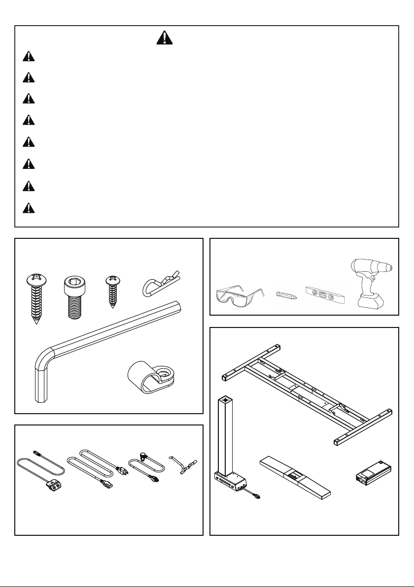
Included Hardware / Tools Other Tools Required
14x M5x25 8x M6x15 13x M3.5x15 2x Cotter Pin
#2 Phillips
Allen Wrench 5mm
10x Cable Clips
Frame Assembly
2x Column
2x Feet Control Box
Keypad Power Cable
2x Cam
Lever
2x Motor
Cable

Page 3 Of 10
1430119200 Rev D
09/2020
- Place worksurface upside down on cardboard or carpeted surface to protect finish.
- Place frame assembly on bottom of worksurface.
Step 1: Worksurface
1
2
- Using the allen wrench, loosen the 8 set screws on frame assembly 1 or 2 turns.
- If using a worksurface with pilot holes, align frame to those holes, sliding the frame apart as needed.
- If using a worksurface without pilot holes, slide the frame apart so the ends are 1” from the side of
the worksurface. Center the frame front to back.
Step 2: Adjust Frame

Page 4 Of 10
1430119200 Rev D
09/2020
- Using a power drill and a #2 Phillips bit, drive 14 - M5x25 screws to attach the frame assembly and
control box to the worksurface. The control box should be placed behind the frame assembly at the
back of the worksurface. There are no pilot holes for the control box location.
Be careful not to overtighten and strip screws.
Screws should be firmly attached to prevent
any movement between the worksurface and
frame assembly / control box.
Step 3: Attach Frame & Control Box
14x M5x25
- Tighten set screws that were loosened in step 2.
Step 4: Tighten Adjustable Frame

Page 5 Of 10
1430119200 Rev D
09/2020
2X
- Insert column into the frame assembly by lining up the protrusions on the column with the slots
in the frame assembly.
- Slide the column back. Ensure the cord is routed under the frame assembly bracket.
- Repeat for the other side.
Step 5: Install Columns

Page 6 Of 10
1430119200 Rev D
09/2020
2X
1
3
2
4
- Remove the cotter pin from the cam lock and save.
- Install the cam lock into frame by sliding the long end into one hole, rotating down, then sliding
the short end into the other hole.
- Rotate the cam lock handle down to lock the column into place.
- Reinstall the cotter pin to prevent the cam lock from unlocking.
- Repeat for other side.
Step 6: Install Cam Locks for Columns

Page 7 Of 10
1430119200 Rev D
09/2020
- Install the feet using 4 – M6x15 screws with the provided allen wrench.
- Loosen the glides using the allen wrench to make leveling easier later.
Step 7: Install Feet
- Place the keypad at the front edge of the worksurface where desired.
- Using a power drill and a #2 Phillips bit, drive 3 - M3.5x15 screws to attach the keypad to the
worksurface.
Step 8: Install Keypad
3x M3.5x15
Be careful not to overtighten screws
to prevent damage to the keypad.
8x M6x15

- Plug in the keypad cable into the control box using either available port.
- Using the motor cables, plug the columns into the control box. The right-angle ends plug into the
top of the control box.
- Plug in the power cable into the control box.
Step 9: Attach Cables
- Use the cable clips and M3.5x15 screws to organize the cables to the underside of the worksurface.
- Do not leave cables hanging.
- Leave enough slack in the power cord to reach electrical outlet when table is at full height.
Step 10: Organize Cables
10x M3.5x15
Page 8 Of 10
1430119200 Rev D
09/2020

TEAM LIFT
- Using 2 people, flip the base over.
- Adjust leveling glides as needed to level base.
- Plug the power cable into an electrical outlet.
Step 11: Prepare for Use
- The base must be initialized before use, after any power loss, and after every 6 months to ensure
proper operation. Remove all obstructions under the base before initializing.
- To initialize, hold down both up and down buttons on the keypad.
- Continue to hold down both buttons as the base lowers to its lowest height, reaches the bottom,
and raises up slightly.
- It is now ok to release the buttons. The base is initialized and ready for use.
Step 12: Initialization
Page 9 Of 10
1430119200 Rev D
09/2020

- This table is equipped with a gyroscopic anti-collision system that is designed to detect unexpected
changes in velocity and quickly reverse the motion of the table. This anti-collision system is only
intended to help reduce the risk of the table causing accidental injury or damage and will not com-
pletely prevent incidents of collision.
Extreme care should always be used when operating this table to ensure no obstructions interfere
with its motion.
Anti-collision
- If the table is not functioning properly, check the following:
o
Verify the base has power from a functioning electrical outlet.
o
Check all cables are securely connected.
o
Verify there is not excessive weight on the worksurface or that it is not distributed across the surface.
o
Perform the initialization procedure from step 12.
- If the table is still not functioning properly, please contact
Allsteel Customer Service at 1-888-255-7833.
Troubleshooting
Page 10 Of 10
1430119200 Rev D
09/2020
Table of contents
Other altitude Industrial Equipment manuals