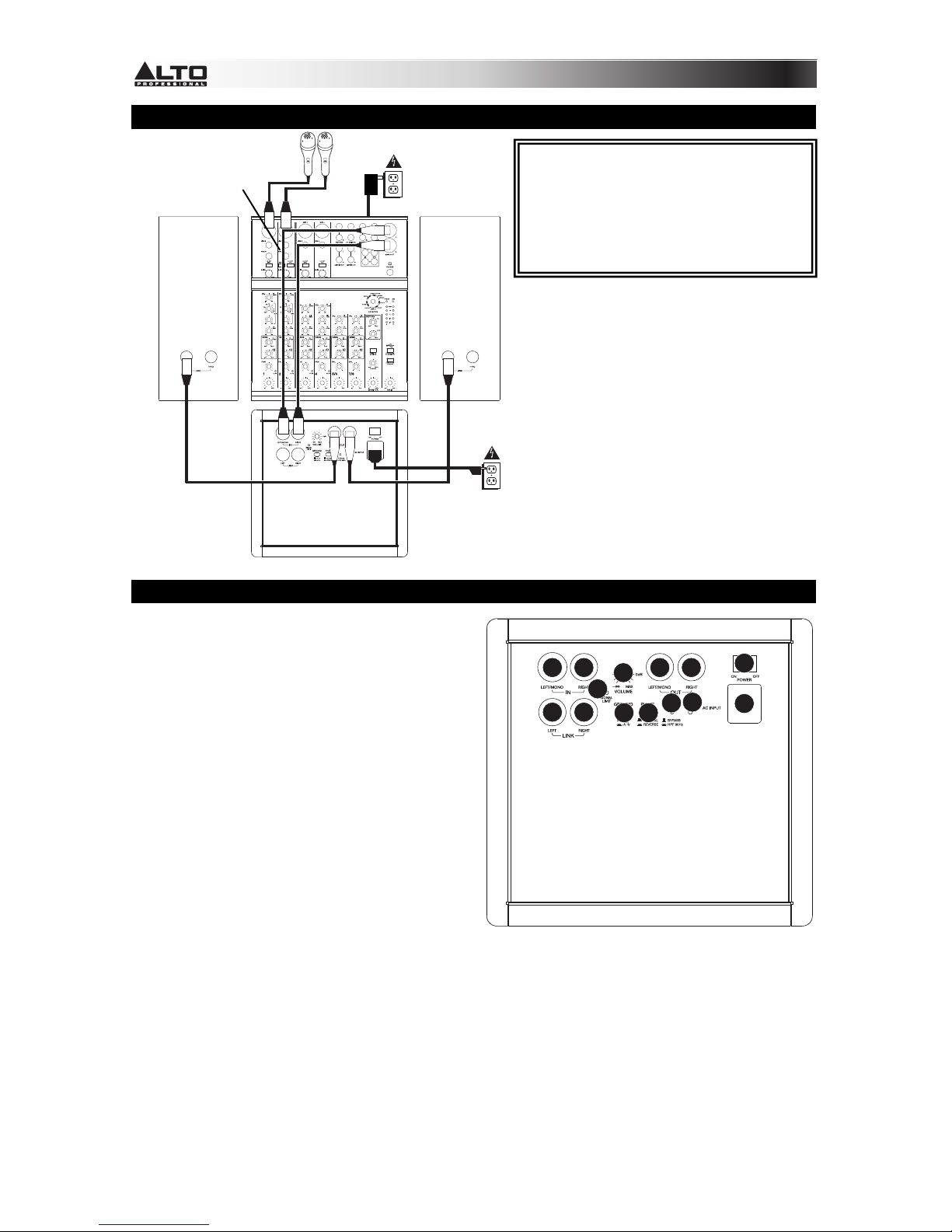
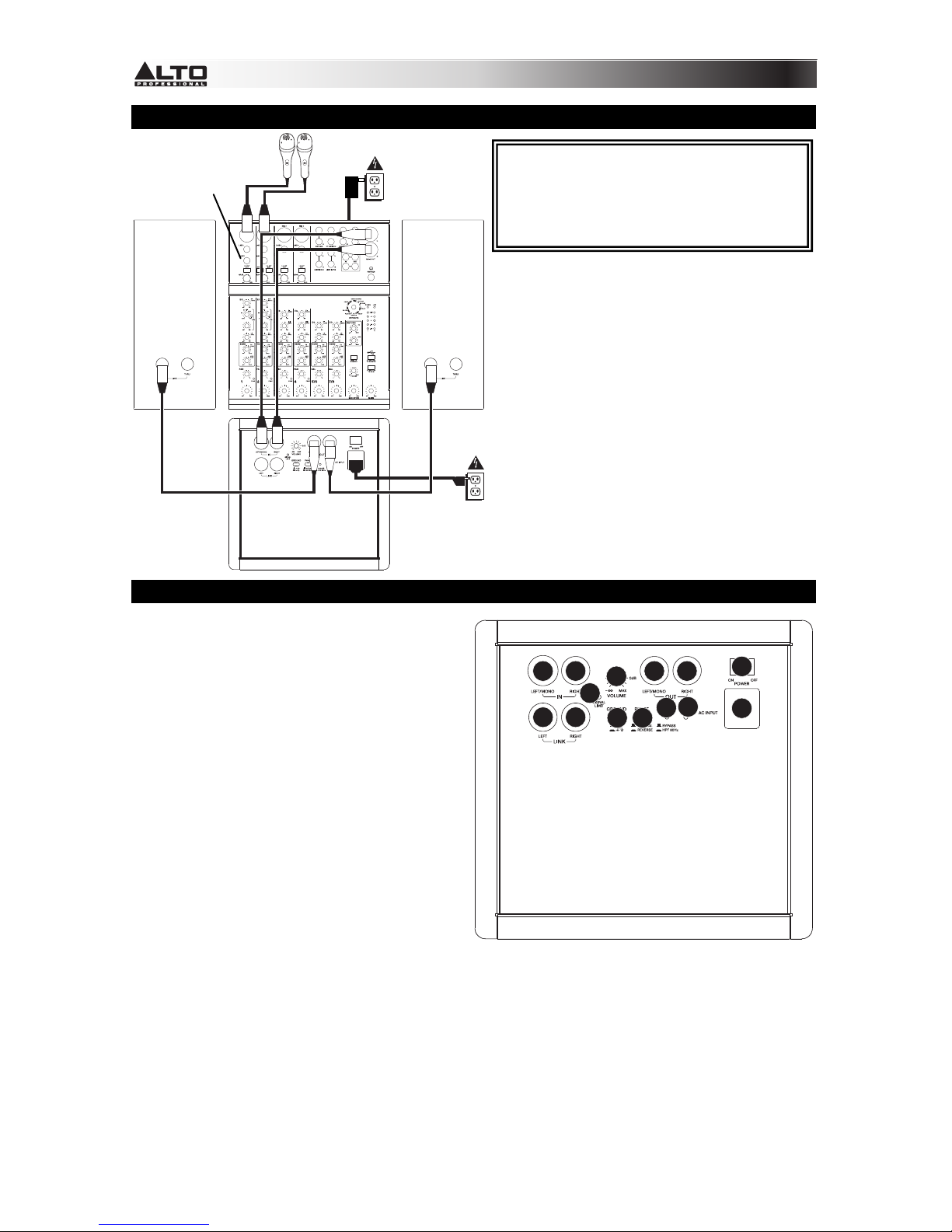
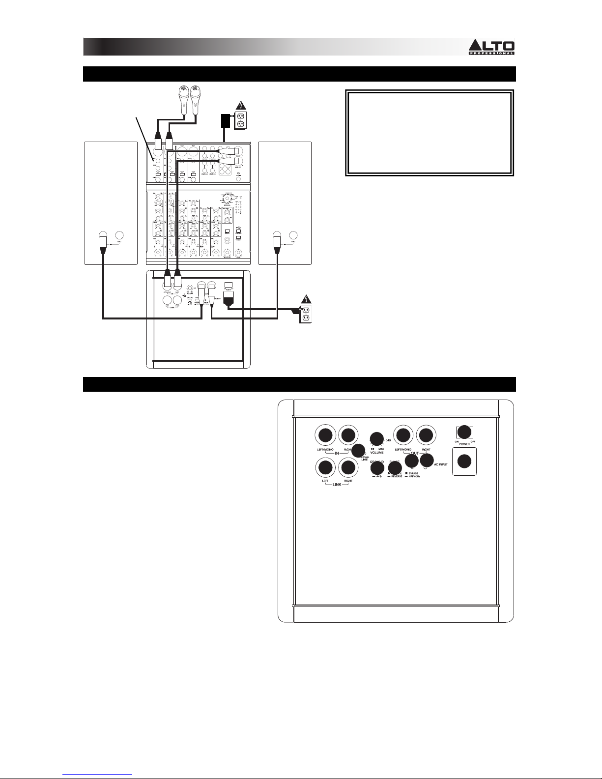
Alto TS SUB 12 TrueSonic User manual

QUICKSTART GUIDE
ENGLISH
GUÍA DE INICIO RÁPIDO
ESPAÑOL
GUIDE D'UTILISATION RAPIDE
FRANÇAIS
GUIDA RAPIDA
ITALIANO
SCHNELLSTART-ANLEITUNG
DEUTSCH
SNELSTARTGIDS
NEDERLANDS

2
CONNECTION DIAGRAM
REAR PANEL OVERVIEW
1. POWER INPUT – Connect the included
power cable to this input and connect the
other end of the cable to a power source.
Make sure the subwoofer's POWER
SWITCH is set to "off" when plugging and
unplugging the cable.
2. POWER SWITCH – Turns the subwoofer
on/off. Make sure the VOLUME knob is set
to "zero" before turning it on.
3. POWER LED – Illuminates when the
subwoofer is on.
4. VOLUME – Turn this knob to adjust the
subwoofer's volume.
5. INPUTS – Use standard XLR cables (not
included) to connect your sound source to
these inputs. The "LEFT/MONO" INPUT can
accept either 1/4" TRS or XLR connections.
(When connecting a mono sound source,
use only the "LEFT/MONO" INPUT.)
6. OUTPUTS – Use standard XLR cables (not
included) to connect the subwoofer to the
inputs of your active speakers or powered amplifier.
7. LINK OUTPUT – Use standard XLR cables (not included) to connect the subwoofer to the inputs of an
additional amplifier (optional).
8. SIGNAL LIMIT LED – Illuminates when the audio signal being sent to the subwoofer is "clipping" or
distorting. If this light illuminates frequently or steadily, reduce the volume of your sound source.
9. GROUND SWITCH – Depressing this switch grounds the subwoofer, which can reduce hum or noise.
10. PHASE SWITCH – Depressing this switch reverses the polarity of the subwoofer's output signal. In
some cases, this can help reduce any interference in the frequency overlap between the subwoofer
and main speaker.
11. BYPASS SWITCH – Depressing this switch activates the subwoofer's high-pass filter (80 Hz).
*Note: Microphones, mixer, speakers,
and cables are not included.
Speaker* Speaker*
Microphones*
Power
Power
Subwoofer
Mixer*
1
2
3
4
55
77
66
8
910
11
BOX CONTENTS
•TRUESONIC subwoofer
•Power cable
•Quickstart Guide
•Safety Instructions & Warranty
Information Booklet

3
DIAGRAMA DE CONEXIÓN
VISTA DEL PANEL TRASERO
1. ENTRADA DE ALIMENTACIÓN – Conecte a esta
entrada el cable de alimentación incluido y luego
conecte el otro extremo del cable al suministro
eléctrico. Asegúrese de que el INTERRUPTOR DE
ENCENDIDO esté en "off" (apagado) cuando
enchufe y desenchufe el cable.
2. INTERRUPTOR DE ENCENDIDO – Enciende y
apaga el altavoz. Asegúrese de que la perilla de
VOLUMEN esté ajustada a "cero" antes de
encenderlo.
3. LED DE ENCENDIDO – Se ilumina cuando el
altavoz está encendido.
4. VOLUMEN – Gire esta perilla para ajustar el
volumen del altavoz.
5. ENTRADAS – Use cables XLR estándar (no
incluidos) para conectar su fuente de sonido a estas
entradas. La ENTRADA "IZQUIERDA/MONO"
puede aceptar conexiones de 1/4" TRS o XLR.
(Cuando conecte una fuente de sonido mono, use
sólo la ENTRADA "IZQUIERDA/MONO".)
6. SALIDAS – Use cables XLR estándar (no incluidos)
para conectar el subwoofer a las entradas de sus altavoces activos o su amplificador alimentado.
7. SALIDA DE ENLACE – Use cables XLR estándar (no incluidos) para conectar el subwoofer a las entradas de
un amplificador adicional (opcional).
8. LED DE LÍMITE DE SEÑAL – Se enciende cuando la señal de audio que se envía al altavoz se "recorta" o
distorsiona. Si esta luz se enciende con frecuencia o en forma permanente, reduzca el volumen de su fuente
de sonido.
9. INTERRUPTOR DE TIERRA – Al oprimir este interruptor, se pone a tierra el subwoofer, con lo que se puede
reducir el zumbido o ruido.
10. CONMUTADOR DE FASE – Al oprimir este conmutador se invierte la polaridad de la señal de salida del
subwoofer. En algunos casos, esto puede ayudar a reducir interferencias en el solapamiento de frecuencias
entre el subwoofer y el altavoz principal.
11. INTERRUPTOR DE DERIVACIÓN – Al oprimir este interruptor se activa el filtro pasaaltos del subwoofer (80
Hz).
*Nota: No se incluyen micrófonos, mezclador,
altavoces y cables.
Altavoz*
Micrófonos*
Potencia
Potencia
Subwoofer
Mezclador*
Altavoz*
1
2
3
4
55
77
66
8
910
11
CONTENIDO DE LA CAJA
•Subwoofer TRUESONIC
•Cable de alimentación
•Guía de inicio rápido
•Folleto de instrucciones de seguridad e
información sobre la
g
arantía

4
SCHÉMA DE CONNEXION
CARACTÉRISTIQUES DU PANNEAU ARRIÈRE
1. ENTRÉE D’ALIMENTATION – Branchez le
câble d’alimentation inclus à cette entrée et
branchez l’autre extrémité à une source
d’alimentation électrique. Assurez-vous que
l’interrupteur de mise en marche est réglé sur
« Off » lorsque vous branchez/débranchez le
câble d’alimentation.
2. INTERRUPTEUR D'ALIMENTATION – Met
l’appareil sous et hors tension. Assurez-vous
que le bouton du volume soit complètement
fermé (« zéro ») avant de mettre le haut-parleur
sous tension.
3. DEL D’ALIMENTATION – S’allume lorsque le
haut-parleur est sous tension.
4. VOLUME – Ce bouton permet d’ajuster le
volume des haut-parleurs.
5. ENTRÉE – Utilisez des câbles XLR (non inclus)
pour brancher une source audio à ces entrées.
L’entrée « LEFT/MONO » peut accueillir une
connexion ¼ po TRS ou XLR. (Lors de
l’utilisation d’une source audio mono, utilisez uniquement l'entrée « LEFT/MONO ».)
6. SORTIES – Utilisez des câbles XLR standard (non inclus) pour brancher le caisson d'extrêmes graves
aux entrées des haut-parleurs actifs ou à l'amplificateur de puissance.
7. SORTIE RELAIS – Utilisez des câbles XLR standard (non inclus) pour brancher le caisson d'extrêmes
graves aux entrées d'un autre amplificateur (facultatif).
8. DEL D'ÉCRÊTEMENT – S’allume pour indiquer l’écrêtement du signal. Si la DEL clignote ou s’allume
de façon constante, diminuez le volume de la source audio.
9. INTERRUPTEUR DE MISE À LA TERRE – Activer cet interrupteur permet de mettre à la terre le
caisson d'extrêmes graves et de réduire les bruits indésirables.
10. INVERSEUR DE PHASE – Cet interrupteur permet d'inverser la polarité du signal de sortie du caisson
d'extrêmes graves. Dans certains cas, ceci permet de réduire les interférences dans le recouvrement
de fréquence entre le caisson d'extrêmes graves et le haut-parleur principal.
11. INTERRUPTEUR DE DÉRIVATION – Cet interrupteur permet d'activer le filtre passe-haut du caisson
d'extrêmes graves (80 Hz).
*Remarqu
e
: Microphones, haut-parleurs,
câbles, console de mixage non inclus.
Haut-
parleur*
Microphones*
Alimentation
électrique
Alimentation
électrique
Caisson d'extrêmes graves
Consoles de mixage*
Haut-
parleur*
CONTENU DE LA BOÎTE
•Caisson d'extrêmes graves TRUESONIC
•Câble d'alimentation
•Guide d’utilisation simplifié
•Consignes de sécurité et informations
concernant la garantie
1
2
3
4
55
77
66
8
910
11

5
SCHEMA DEI COLLEGAMENTI
PANORAMICA PANNELLO POSTERIORE
1. INGRESSO DI ALIMENTAZIONE – Collegare il
cavo di alimentazione in dotazione a questo
ingresso, quindi collegare l’altro capo del cavo
stesso ad una sorgente di alimentazione.
Assicurarsi che l'INTERRUTTORE DI
ALIMENTAZIONE dell'altoparlante sia su "off" al
momento di collegare e scollegare il cavo.
2. INTERRUTTORE DI ALIMENTAZIONE
(POWER) – Accende e spegne l'altoparlante.
Assicurarsi che la manopola VOLUME sia
impostata su "zero" prima di accenderlo.
3. LED DI ALIMENTAZIONE – Si illumina quando
l'altoparlante è acceso.
4. VOLUME – Girare questa manopola per
regolare il volume dell'altoparlante.
5. INGRESSI – Servirsi di cavi stereo XLR (non in
dotazione) per collegare sorgenti sonore a
questi ingressi. L'INGRESSO "LEFT/MONO"
accetta collegamenti TRS o XLR da 1/4". (Al
momento di collegare una fonte audio mono,
servirsi unicamente dell'ingresso "LEFT/MONO")
6. USCITE – Servirsi di cavi standard XLR (non in dotazione) per collegare il subwoofer agli ingressi degli
altoparlanti attivi o a un amplificatore alimentato.
7. USCITA LINK – Servirsi di cavi standard XLR (non in dotazione) per collegare il subwoofer agli
ingressi di un amplificatore aggiuntivo (opzionale).
8. LED LIMITE DI SEGNALE – Si accende quando il segnale audio inviato all'altoparlante "salta" o viene
distorto. Se questa spia si accende spesso o in maniera fissa, ridurre il volume della fonte audio.
9. INTERRUTTORE DI MESSA A TERRA – La pressione di questo interruttore mette a terra il
subwoofer, riducendo ronzii o rumore.
10. INTERRUTTORE PHASE (FASE) – Premendo questo interruttore si inverte la polarità del segnale di
uscita del subwoofer. In alcuni casi, questo aiuta a ridurre qualsiasi interferenza nella sovrapposizione
di frequenze tra il subwoofer e l'altoparlante principale.
11. INTERRUTTORE BYPASS – Premendo questo interruttore si attiva il filtro passa alto del subwoofer
(80 Hz).
*Nota bene: microfoni, mixer, altoparlanti e cavi
non in dotazione.
Altoparlante* Altoparlante*
Microfoni*
Alimentazione
Alimentazione
Subwoofer
Mixer*
CONTENUTI DELLA CONFEZIONE
•Subwoofer TRUESONIC
•Cavo di alimentazione
•Guida rapida
•Istruzioni di sicurezza e garanzia
1
2
3
4
55
77
66
8
910
11

6
ANSCHLUSSÜBERSICHT
ÜBERSICHT RÜCKSEITE
1. NETZEINGANG – Verbinden Sie das
mitgelieferte Netzkabel mit diesem Eingang und
das andere Ende des Kabels mit einer
Stromquelle. Achten Sie darauf, dass der
NETZSCHALTER des Lautsprechers auf "off"
steht, wenn Sie das Kabel anschließen oder
abstecken.
2. NETZSCHALTER – Schaltet den Lautsprecher
ein/aus. Achten Sie darauf, dass der
LAUTSTÄRKE-Regler auf "Null" steht, bevor Sie
den Lautsprecher einschalten.
3. POWER-LED – Leuchtet, wenn der Lautsprecher
eingeschaltet ist.
4. LAUTSTÄRKE – Drehen Sie diesen Knopf, um
die Lautstärke des Lautsprechers einzustellen.
5. EINGÄNGE – Verwenden Sie handelsübliche
XLR-Kabel (nicht im Lieferumfang enthalten), um
Ihre Tonquelle mit diesen Eingängen zu
verbinden. Der "LEFT/MONO"-EINGANG
benötigt 1/4"-Klinken oder XLR-Verbindungen.
(Bei Anschluss einer Mono-Tonquelle verwenden
Sie nur den "LEFT/MONO"-EINGANG.)
6. AUSGÄNGE – Verwenden Sie handelsübliche
XLR-Kabel (nicht im Lieferumfang enthalten), um den Subwoofer mit den Eingängen der Aktiv-Lautsprecher
oder den Ihre Endstufe zu verbinden.
7. LINK-AUSGANG – Verwenden Sie handelsübliche XLR-Kabel (nicht im Lieferumfang enthalten), um den
Subwoofer mit den Eingängen eines zusätzlichen Verstärkers zu verbinden (optional).
8. LIMIT-LED – Leuchtet auf, wenn das an den Lautsprecher gesendete Audiosignal "clippt" oder verzerrt. Sollte
diese LED häufig oder ständig leuchten, reduzieren Sie die Lautstärke Ihrer Tonquelle.
9. ERDUNGSSCHALTER – Das Betätigen dieses Schalters erdet den Subwoofer, wodurch Brummgeräusche
oder Rauschen vermindert werden können.
10. PHASENSCHALTER – Das Herunterdrücken dieses Schalters ändert die Polarität des Subwoofer-
Ausgangssignals. In einigen Fällen kann dies Interferenzen bei der Frequenzüberlappung zwischen Subwoofer
und Haupt-Lautsprecher reduzieren.
11. BYPASS-SCHALTER – Das Herunterdrücken dieses Schalters aktiviert den Subwoofer-Hochpassfilter (80
Hz).
*Hinweis: Mikrofone, Mixer, Lautsprecher und Kabel
sind nicht im Lieferumfang enthalten.
Lautsprecher*
Mikrofone*
Stromversorgung
Stromversorgung
Subwoofer
Mixer*
Lautsprecher*
LIEFERUMFANG
•TRUESONIC Subwoofer
•Netzkabel
•Schnellstart-Anleitung
•Sicherheitshinweise und Garantieinformationen
1
2
3
4
55
77
66
8
910
11

7
VERBINDINGSDIAGRAM
OVERZICHT ACHTERPANEEL
1. POWER INPUT – Sluit de meegeleverde
stroomkabel aan op deze ingang en sluit
het andere uiteinde van de kabel aan op
een stroombron. Zorg ervoor dat de
POWER-schakelaar van de luidspreker op
"off" staat bij het aansluiten en loskoppelen
van de kabel.
2. POWER SWITCH – Schakelt de
luidspreker aan/uit. Zorg ervoor dat de
VOLUME-knop op "nul" staat voor het
inschakelen.
3. POWER LED – Brandt wanneer de
luidspreker is ingeschakeld.
4. VOLUME – Draai deze knop om het
luidsprekervolume aan te passen.
5. INPUTS – Gebruik standaard XLR-kabels
(niet meegeleverd) om uw geluidsbron te
verbinden met deze ingangen. De ingang
"LEFT/MONO" aanvaardt zowel 1/4" TRS-
als XLR-plugs. (Gebruik alleen de ingang
"LEFT/MONO" bij verbinding van een
mono geluidsbron.)
6. OUTPUTS – Gebruik standaard XLR-
kabels (niet meegeleverd) om de
subwoofer aan te sluiten op de ingangen van uw actief speakers of op de versterker.
7. LINK OUTPUT – Gebruik standaard XLR-kabels (niet meegeleverd) om de subwoofer aan te sluiten op de
ingangen van een extra versterker (optioneel).
8. SIGNAL LIMIT LED – Gaat branden wanneer het audiosignaal, verzonden naar de luidspreker, begint te
"clippen" of vervormd is. Als dit lampje vaak of gestaag brandt, verlaag dan het volume van uw geluidsbron.
9. GROUND SWITCH – Druk deze knop in om de subwoofer te aarden, wat brom of ruis kan verminderen.
10. PHASE SWITCH – Het indrukken van deze schakelaar draait de polariteit om van het uitgangssignaal van de
subwoofer. In sommige gevallen kan dit storingen helpen verminderen wanneer de frequenties van de
subwoofer en hoofdspeaker elkaar overlappen.
11. BYPASS SWITCH – Het indrukken van deze schakelaar activeert het hoogdoorlaatfilter van de subwoofer (80
Hz).
*Opmerking: Microfoons, mengpaneel,
luidsprekers en kabels zijn niet inbegrepen.
Luidspreker* Luidspreker*
Microfoons*
Stroom
Stroom
Subwoofer
Mengpaneel* INHOUD VAN DE DOOS
•TRUESONIC subwoofer
•Stroomkabel
•Snelstartgids
•Veiligheidsvoorschriften & boekje
met informatie over de garantie
1
2
3
4
55
77
66
8
910
11

SPECIFICATIONS
Output Power: 300 W Continuous RMS, 600 W Peak
Crossover: L-R output with high-pass filter at 80 Hz
Max SPL @ 1m: 120 dB Continuous, 123 dB Peak
Frequency Response: 47 Hz – 125 Hz (@ -10 dB)
Low Frequency: 12" (305 mm) woofer, 2.5" (64 mm) voice coil, with double ventilation
Input Level: L-R input line at 0dBu
Connectors: Input: Left/mono 1/4" TRS or XLR; Right XLR
Output: Left/mono XLR; Right XLR
Link: Left/mono XLR; Right XLR
Cabinet: 15 mm plywood, glued and reinforced, resistant black paint finish,
metal grille, rubber feet
External Control: Volume control, phase switch, HPF (80Hz or bypass), power-on with LED,
clip limiter with LED, ground lift
Power supply: 100-120V/220-240V, 50/60 Hz
Dimensions (H x W x D): 14.6" x 20.9" x 18.9" (370 mm x 530 mm x 480 mm)
Weight (speaker only): 41 lbs (18.6 kg)
Inrush current at initial switch-on: 5.34 A
Inrush current after power supply interruption: 4.35 A
www.altoprofessional.com
MANUAL VERSION 1.1
Table of contents
Languages:
Other Alto Subwoofer manuals

Alto
Alto SR500SA User manual

Alto
Alto SX-SUB18 TOURMAX User manual

Alto
Alto tssub15 truesonic User manual

Alto
Alto SX-SUB15 TOURMAX User manual

Alto
Alto TS212S User manual

Alto
Alto BLACK 15 SUB User manual

Alto
Alto X23SW User manual

Alto
Alto SX SUB I5 TOURMAX User manual

Alto
Alto TRUESONIC TS-SUB18 User manual