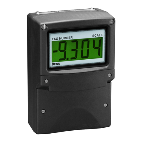
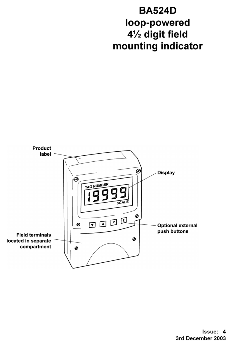
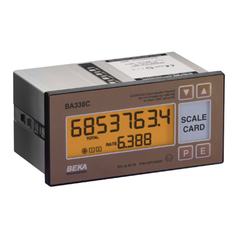
BEKA BA304NC User manual

Issue: 5
11th November 2009
BA304NC
Type nL
Loop-powered
3½ digit field
mounting indicator
issue 5

2
1. Description
2. Operation
3. Type ‘nL’ Certification
3.1 ATEX Certificate
3.2 Zones, gas groups & T rating
3.3 Input parameters
3.4 Certification label information
4. System Design for Zone 2
4.1 Transmitter loops
4.2 Remote indication
5. Installation
5.1 Location
5.2 Installation procedure
5.3 EMC
6. Calibration
6.1 Zero adjustment
6.2 Span adjustment
6.3 Decimal point
6.4 Reverse action
6.5 Calibration example
6.6 Over and under-range
7. Maintenance
7.1 Fault finding during commissioning
7.2 Fault finding after commissioning
7.3 Servicing
7.4 Routine maintenance
7.5 Guarantee
7.6 Customer comments
8. Accessories
8.1 Engraved scale and tag plates
8.2 Root extractor
8.2.1 Calibration example
8.3 Display backlight
8.4 Pipe mounting kits
8.5 Panel mounting kit
The BA304NC is CE marked to show compliance with the
European Explosive Atmospheres Directive 94/9/EC
and the European EMC Directive 2004/108/EC
CONTENTS

3
1. DESCRIPTION
The BA304NC is an Ex nL certified loop powered
digital indicator which displays the current flowing
in a 4/20mA loop in engineering units. The
instrument introduces less than a 1.1V drop which
allows it to be installed into almost any 4/20mA
current loop. No additional power supply or battery
is required.
The main application of the BA304NC is to display
a measured variable or control signal in a Zone 2
hazardous process area. The zero and span of
the display are independently adjustable so that
the indicator may be calibrated to display any
variable represented by the 4/20mA current, e.g.
temperature, flow, pressure or level.
The BA304NC complies with the European ATEX
Directive for Group II Category 3G equipment and
has been issued with an EC Declaration of
Conformity.
The indicator is available in a glass reinforced
polyester (GRP), or an epoxy painted aluminium
enclosure. Both provide IP66 protection.
2. OPERATION
Fig 1 shows a simplified block diagram of a
BA304NC. The 4/20mA input current flows
through resistor R1 and forward biased diode D1.
The voltage developed across D1, which is
relatively constant, is multiplied by a switch mode
power supply and used to power the analogue to
digital converter and liquid crystal display. The
voltage developed across R1, which is proportional
to the 4/20mA input current, provides the input
signal for the analogue to digital converter.
Fig 1 Simplified block diagram of BA304NC
3. TYPE ‘nL’ CERTIFICATION
3.1 ATEX certificate
The BA304NC complies with the European ATEX
Directive 94/9/EC for Group II, Category 3G
equipment. It has been assessed using the
‘Internal Control of Production’ procedure specified
in Annex 8 of the Directive. A technical dossier
has been prepared and an EC Declaration of
Conformity BEKA03ATEX0015 has been issued.
The instrument bears the Community Mark and,
subject to local codes of practice, may be installed
in any of the European Economic Area (EEA)
member countries. i.e. Austria, Belgium,
Denmark, Finland, France, Germany, Greece,
Ireland, Italy, Luxembourg, Norway, The
Netherlands, Portugal, Spain, Sweden and the
United Kingdom. ATEX certificates are also
accepted in Iceland, Liechtenstein, Switzerland
and the Czech Republic.
This instruction manual describes installations
which conform with BS EN60079:Part 14 Electrical
Installation in Hazardous Areas. When designing
systems for installation outside the UK, the local
Code of Practice should be consulted.

4
3.2 Zones, Gas Groups and T rating
The BA304NC has been certified as Group II,
Category 3G apparatus as defined in the ATEC
Directive and as Ex nL IIC T5 Tamb -40 to 60oC.
‘L’ indicates that the BA304NC uses an energy-
limiting technique to achieve compliance as
defined in EN 60079-15. This technique is based
on the philosophy of intrinsic safety which limits the
current and voltage applied to components which
may generate a spark in normal operation. e.g.
switches and potentiometers
These approvals confirm that the BA304NC is safe
in normal operation and may be:
Installed in a Zone 2 hazardous area
At ambient temperatures between
-40 to 60oC.
Used in gase groups:
Group A propane
Group B ethylene
Group C hydrogen
Having a temperature classification of:
T1 450ºC
T2 300ºC
T3 200ºC
T4 135ºC
T5 100ºC
Although certified safe in normal operation at
ambient temperatures between –40 and +60ºC,
the guaranteed operating temperature range of
the BA304NC is –20 to +60ºC.
This allows the BA304NC indicator to be installed
in a Zone 2 low risk hazardous area and to be
used with most common industrial gases.
3.3 Input parameters
Input terminals 1 and 3 may be safely connected in
series with any 4/20mA loop providing that in
normal operation the input current to the indicator
does not exceed 40mA.
3.4 Certification Label Information
The certification information label is fitted on the
top outer surface of the enclosure. It shows the
ATEX certification information plus BEKA
associates name and location.
The instrument serial number and date of
manufacture are shown on a separate label within
the instrument enclosure.
4. SYSTEM DESIGN FOR ZONE 2
4.1 Transmitter loops
A BA304NC indicator may be connected in series
with almost any 4/20mA current loop and
calibrated to display the measured variable or
control signal in engineering units.
Fig 2 illustrates a typical application in which a
BA304NC indicator is connected in series with a 2-
wire transmitter and controller.
Fig 2 BA304NC in a transmitter loop
There are four basic design requirements:
1. In normal operation the voltage, current
and power applied to the terminals 1 and 3
of the BA304NC must not exceed:
Ui = 4V
Ii = 40mA dc
Pi = 0.2W
Providing the maximum input current in
normal operation is less than 40mA, the
maximum voltage between the indicator
terminals and the maximum input power to
the indicator will be automatically limited to
less than the above figures by the internal
safety components.

5
2. Apparatus in safe area must not be
supplied from nor contain under normal
conditions a source of potential with
respect to earth in excess of 250V rms or
250V dc.
3. Both M20 entries must be fitted with an Ex
e or Ex n certified cable gland or blanking
plug.
4. The 4/20mA loop must be able to tolerate
the additional 1.1V required to operate the
indicator.
CAUTION !
The enclosure cover should only be
removed when the measuring loop is not
energised, or when there is no risk of a
flammable atmosphere being present and
dust or water can not enter the
enclosure. Before replacing the
enclosure cover ensure that the sealing
gasket is undamaged and that it is free
from dirt and foreign bodies.
In practice it is only necessary to ensure that in
normal operation the maximum current flowing in
the 4/20mA loop is less than 40mA. Fig 2 shows
a temperature measuring loop in which the
maximum current in normal operation is defined by
the maximum output from the Type n transmitter.
The sum of the maximum voltage drops of all the
components in the loop must be less than the
minimum power supply voltage. Considering the
example shown in Fig 2.
Minimum operating voltage of 2-wire Tx 10.0
Maximum voltage drop caused by controller 5.0
Maximum voltage drop caused by BA304NC 1.1
Maximum voltage drop caused by cables 0.4
_____
16.5V
Therefore at 20mA the power supply in this
example must have an output greater than 16.5V
4.2 Remote indication
A BA304NC indicator may be driven from a
4/20mA safe area signal to provide a remote
indication within a Zone 2 hazardous area. Fig 3
shows a typical application in which the output
from a gas analyser drives a BA304NC. Again it is
necessary to ensure that the loop complies with
the three design requirements listed in section 4.1.
Fig 3 Remote indication
5. INSTALLATION
5.1 Location
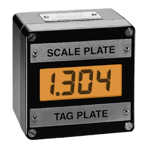
The BA304NC indicator can be supplied in either a
glass reinforced polyester (GRP), or an epoxy
painted aluminium enclosure. Both provide IP66
protection and have a polycarbonate window and
stainless steel fittings. The GRP enclosure is
suitable for most industrial installations including
off-shore and waste water treatment applications.
For installations where solvents may be present,
the aluminium enclosure provides maximum
protection, but it is not recommended for offshore
applications.
Both enclosures are surface mounting, but may be
pipe or panel mounted using the accessory kits
described in section 8 of this manual.
To simplify installation, the enclosure can be
installed and the field wiring terminated prior to the
indicator assembly being fitted. The enclosure
contains diodes to maintain continuity of the
4/20mA loop when the indicator assembly is not
present. Terminals 2 and 4 are internally joined
and may be used for linking the return 4/20mA wire
- see Fig 2. Similarly, terminals 5 and 6 are
internally joined and may be used for linking the
cable screens. Terminal 7 is internally connected
to an insulated radio frequency screen in the GRP
enclosure, and to the case in the aluminium
enclosure .
6
5.2 Installation Procedure
Fig 4 illustrates the instrument installation
procedure.
a. Remove the enclosure cover by unscrewing
the four captive 'A' screws.
b. Remove the indicator assembly from the
enclosure by unscrewing the three captive 'B'
screws.
c. Mount the enclosure on a flat surface and
secure with screws or bolts through the four
corner 'C' holes. Alternatively use one of the
pipe or panel mounting kits described in
sections 8.4 and 8.5
d. Remove the temporary dust seals from the
two cable entries and install Ex e or Ex n
certified glands, conduit fittings or blanking
plugs.
e. Connect the field wiring to the terminals as
shown in Fig 5.
f. Replace the indicator assembly and evenly
tighten the three 'B' screws.
g. Replace the enclosure cover and evenly
tighten the four 'A' screws.
Fig 4 BA304NC installation procedure
5.3 EMC
The BA304NC complies with the requirements of
the European EMC Directive 89/336/EEC. For
specified immunity all 4/20mA wiring should be in
screened twisted pairs, with the screen earthed
within the safe area. Terminal 7 should be
connected to a local earth or to a cable screen
which is earthed in the safe area.
Fig 5 Dimensions and terminal connections

7
6. CALIBRATION
The BA304NC will be supplied calibrated as
requested at time of ordering. If calibration is not
requested, the indicator will be set to display 00.0
with 4.000mA input, and 100.0 with 20.000mA
input.
The BA304NC is conditioned and calibrated by
plug-in links and two multi-turn potentiometers.
For maximum accuracy, the instrument should be
calibrated using an external traceable current
source with a resolution of at least 4µA.
Fig 6 Location of calibration links
and potentiometers
6.1 Zero adjustment
Zero is defined as the number displayed by the
indicator with a 4.000mA input current and may be
adjusted between -1000 and 1000. The zero
potentiometer has two ranges, 0 to 500 and 500 to
1000. Zero polarity is defined by the position of
the suppression / elevation links which are shown
in Fig 6.
Suppression / elevation links
Position Display with 4mA input
adjustable between
Elevation 0 and 1000
Suppression 0 and -1000
Zero link
Position Display with 4mA input
adjustable between
0 to 500 0 and 500
500 to 1000 500 to 1000
6.2 Span adjustment
Span is defined as the difference between the
number displayed with 4.000mA input and the
number displayed with 20.000mA input. It is
adjustable between 0 and 1999 in four ranges. Fig
6 shows the position of the span links and the span
potentiometer.
Difference in display
Position with 4 & 20mA input
of span links adjustable between
000 to 500 000 and 500
or 500 to 1000 500 and 1000
or 1000 to 1500 1000 and 1500
or 1500 to 1999 1500 and 1999
6.3 Decimal point
A dummy decimal point may be displayed between
any of the four digits. The position or absence of
this dummy decimal point is determined by the
position of the decimal point link shown in Fig 6.
When calculating the required span and zero
settings the decimal point should be ignored.
6.4 Reverse action
Normally the BA304NC display increases as the
input current increases, but this can be reversed.
Please contact BEKA associates for details.

8
6.5 Calibration example
The BA304NC is required to display:
25.0 with 4.000mA input
115.0 with 20.000mA input
i.e. A zero of positive 250 (Ignoring decimal point)
A span of 900 (Ignoring decimal point)
A decimal point in position 00.0
The following adjustments are required:
Step 1 The BA304NC is required to display a
positive zero therefore the suppression
/ elevation links should be put in the
elevation position.
Step 2 The required zero is 250, therefore the
zero link should be put in the 0 to 500
position.
Step 3 The required span is 900, therefore the
span links should be placed in the 500
to 1000 position.
Step 4 The decimal point is required in front of
the least significant digit, therefore the
decimal point link should be placed in
the 00.0 position.
Step 5 With 4.000mA input adjust the zero
potentiometer until the indicator
displays 25.0
Step 6 With 20.000mA input adjust the span
potentiometer until the indicator
displays 115.0
Step 7 Repeat steps 5 and 6 until both
calibration points are correct. The span
and zero controls are almost
independent so it should only be
necessary to repeat each adjustment
twice.
6.6 Over and under-range
If the indicator display range is exceeded, the three
least significant digits will be blanked. Under-
range is indicated by -1 and over-range by 1. If
the display range is not exceeded, the BA304NC
will produce accurate readings outside the 4/20mA
current range. Although not guaranteed, most
BA304NC indicators will operate between 3 and
25mA.

9
7. MAINTENANCE
7.1 Fault finding during commissioning
If the BA304NC fails to function during
commissioning the following procedure should be
followed:
Symptom Cause Solution
No display Incorrect There should be 1V
wiring between terminals 1 &
3 with terminal 1
positive.
No display Incorrect Check that a current
with 0V wiring or is flowing in the loop.
between no power
terminals 1 supply.
and 3.
Insufficient Check supply voltage
loop voltage and voltage drops
to operate caused by all
BA304NC. components in the loop.
No display Indicator Check that the three
with 4V assembly screws securing the
between not correctly indicator assembly are
terminals 1 installed in tightened.
and 3 enclosure.
BA304NC Positive The BA304NC has been
displays 1 over-range incorrectly calibrated &
is trying to display a
number greater than
1999.
BA304NC Negative The BA304NC has been
displays -1 over-range incorrectly calibrated &
is trying to display a
number less than
-1999.
Unstable 4/20mA Check loop supply
display input has a voltage.
large ripple
7.2 Fault finding after commissioning
CAUTION!
ENSURE PLANT SAFETY BEFORE
STARTING MAINTENANCE
Live maintenance should only be
performed when there is no risk of a
flammable atmosphere being present,
and dust or water can not enter the
enclosure. Before replacing enclosure
cover ensure that the sealing gasket is
undamaged and free from dirt and
foreign bodies.
If a BA304NC fails after it has been functioning
correctly, the following procedure should be
followed:
Symptom Cause Solution
No display No power Check that a current
with 0V supply is flowing in the loop.
between
terminals 1
and 3
No display Indicator Check that the three
with 4V assembly screws securing the
between not correctly indicator assembly are
terminals 1 installed in tightened.
and 3 enclosure.
Unstable 4/20mA Check loop supply
display input has a voltage.
large ripple
If this procedure does not reveal the cause of the
fault, it is recommended that the indicator
assembly is removed from the enclosure and
replaced. This can be done without disconnecting
power. If the replacement assembly functions, the
fault is within the original indicator assembly. If the
indicator is still faulty, it is likely that the fault is
within the enclosure assembly or field wiring.

10
7.3 Servicing
CAUTION!
ENSURE PLANT SAFETY BEFORE
STARTING MAINTENANCE
Live maintenance should only be
performed when there is no risk of a
flammable atmosphere being present,
and dust or water can not enter the
enclosure. Before replacing enclosure
cover ensure that the sealing gasket is
undamaged and free from dirt and
foreign bodies.
To simplify servicing, all ATEX certified BA304NC
indicators use a common indicator assembly which
may be replaced on site. All ATEX certified
BA304NC indicator assemblies without
accessories are interchangeable.
To replace the indicator assembly remove the
three 'B' screws shown in Fig 4 which will allow the
assembly to be removed. If the instrument is fitted
with a backlight the fly-lead connecting it to the
terminals must be un-plugged. The replacement
indicator assembly may then be installed and the
enclosure reassembled.
Please note that an ATEX certified BA304NC
indicator assembly must not be replaced by a non
ATEX certified BA304NC assembly. The product
code label on all ATEX certified indicator
assemblies carry the legend ‘ATEX’.
If after replacement of the indicator assembly the
instrument still does not function, it is likely that the
fault is within the protection components on the
terminal assembly. Terminal assemblies may also
be replaced on site providing that an instrument
with a backlight is fitted with a replacement board
including terminals 12 and 13.
We recommend that faulty instruments
and instrument assemblies are returned
to BEKA associates or your local BEKA
agent for repair.
7.4 Routine maintenance
The mechanical condition of the instrument and
the electrical calibration should be regularly
checked. The interval between inspections
depends upon environmental conditions. We
recommend that initially instrument calibration
should be checked annually.
7.5 Guarantee
Indicators which fail within the guarantee period
should be returned to BEKA associates or your
local BEKA agent. It is helpful if a brief description
of the fault symptoms is provided.
7.6 Customer comments
BEKA associates is always pleased to receive
comments from customers about our products and
services. All communications are acknowledged
and whenever possible, suggestions are
implemented.

11
8. ACCESSORIES
8.1 Engraved scale and tag plates
All BA304NC indicators are fitted with blank
stainless steel scale and tag plates above and
below the display. These can easily be removed
for engraving, or if requested they can be supplied
engraved with any units of measurement and tag
information. Each plate can accommodate:
1 row of 9 alphanumeric characters 10mm
high.
or 1 row of 11 alphanumeric characters 7mm
high.
or 2 rows of 18 alphanumeric characters 5mm
high.
8.2 Root extractor
The BA304NC can be supplied with a square root
extractor which enables the indicator to accurately
display the output from a differential flow meter in
linear engineering units between 10 and 100% of
full flow (4.16 to 20mA). The root extractor
continues to operate with reduced accuracy down
to 2.5% of maximum flow, or clip-off can be
selected which will force the display to zero at
flows below 5% (4.04mA). The location of the clip-
off link is shown in Fig 7.
Fig 7 Location root extractor clip-off link
When calibrating a root extracting BA304NC the
indicator zero potentiometer should be adjusted to
give the required display at 10% of flow (4.16mA).
The indicator zero potentiometer should not be
used to set the display to zero with a 4mA input.
Zero suppression or elevation may not be used,
i.e. 4mA must correspond to zero flow.
For reference, the following table shows the output
current from a non-linearised differential flowmeter.
% of full flow Current output mA
2.5 4.01
10.0 4.16
25.0 5.00
50.0 8.00
75.0 13.00
100.0 20.00
8.2.1 Calibration example with root extractor
The BA304NC is required to display rate of flow in
gallons per minute, with a resolution of 0.1 gallons.
The differential flowmeter has an output of 20mA
at a flow rate of 140.0 gallons per minute.
i.e. A span of 1400 ignoring the decimal point
A decimal point in position 00.0
The following adjustments are required:
Step 1 Put the suppression / elevation links in
the elevation position.
Step 2 Put the zero link in the 0 to 500
position.
Step 3 The required span is 1400, therefore
the span links should be placed in the
1000 to 1500 position.
Step 4 The decimal point is required between
the least two significant digits, therefore
the decimal point link should be placed
in the 00.0 position.
Step 5 With 4.160mA input current adjust the
zero potentiometer until the indicator
displays 14.0 (10% of flow). If there
is insufficient adjustment to achieve
this, put the elevation/suppression links
in the suppression position and
continue with the calibration procedure.

12
Step 6 With 20.000mA input current adjust the
span potentiometer until the indicator
displays 140.0
Step 7 Repeat steps 5 and 6 until both
calibration points are correct.
8.3 Display backlight
The BA304NC can be supplied with LED
backlighting to improve display contrast in poorly
illuminated areas. This backlight is electrically
segregated from the measuring circuit and has
been certified as a separate Ex nL Group II,
Category 3G circuit.
The Type n input safety parameters ae:
Ui = 30V dc
Ii = 100mA
Pi = 1.3W
This allows the backlight to be powered from a
safe area 18 to 30V dc supply as shown in Fig 8.
Providing the supply voltage is less than 30V dc in
normal operation the backlight safety components
will ensure that the maximum input current and
power are within the safety limits.
Fig 8 Separately powered backlight
Reducing the supply voltage below 18V will reduce
the backlight brilliance.
8.4 Pipe mounting kits
Two pipe mounting kits are available for securing
the BA304NC to a horizontal or vertical pipe.
BA392C Stainless steel bracket secured by two
worm drive hose clips. For 60 to 80mm
outside diameter pipes.
BA393 Heavy duty stainless steel bracket
secured by a single 'V' bolt. Will clamp
to any pipe with an outside diameter
between 40 and 80mm.
8.5 Panel mounting kit
The BA394 stainless steel panel mounting kit will
secure a BA304NC indicator into a panel aperture,
but it does not seal the joint between the indicator
enclosure and the instrument panel.
Other manuals for BA304NC
1
This manual suits for next models
1
Table of contents
Other BEKA Measuring Instrument manuals

BEKA
BEKA BA314E User manual

BEKA
BEKA BA558C User manual

BEKA
BEKA BA364ND User manual

BEKA
BEKA BA488CF-P PROFIBUS PA User manual

BEKA
BEKA BA314NG User manual

BEKA
BEKA BA444NDF-P Installation and operating instructions

BEKA
BEKA BA418CF-F Installation and operating instructions

BEKA
BEKA BA504G User manual

BEKA
BEKA BA307C User manual

BEKA
BEKA BA304NE User manual