manuals.online logo
Brands
  1. Home
  2. •
  3. Brands
  4. •
  5. Altronix
  6. •
  7. Power Supply
  8. •
  9. Altronix AL100UL User manual

Altronix AL100UL User manual

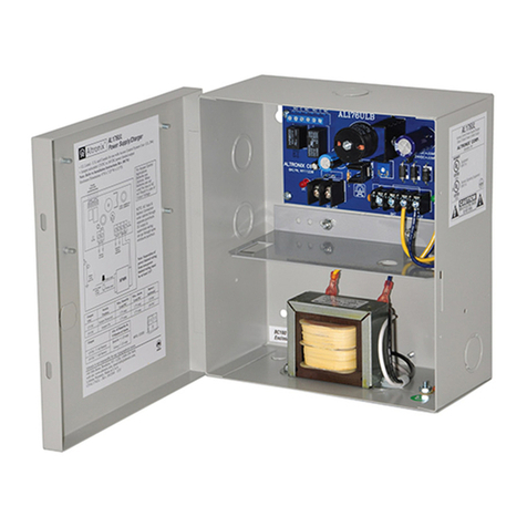
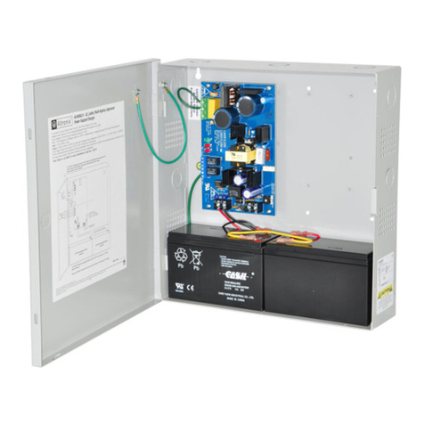
AL100UL
UL Listed
Linear Power Supply/Charger
Installation Guide
Rev. 050101 More than just power.TM
Installing Company: _______________ Service Rep. Name: __________________________________
Address: _____________________________________________ Phone #: __________________
- 2 - AL100UL Installation Guide
Agency Listings:
• UL Listed Standard for Power Supplies for Use with
Burglar Alarm System Units (UL 603).
Burglar Alarm System Power Supply.
• CUL Listed - CSA Standard
C603-M1988, Burglar Alarm System.
Input:
• 16.5VAC, 20VA from UL Listed Class 2
transformer (sold separately).
Output:
• 12VDC Class 2 Rated power-limited output.
• 750mA continuous supply current at 12.5 to 13.9VDC.
• Filtered and electronically regulated output.
Supervision:
• Low battery and AC fail supervision
form “C” contacts (1A @ 28VDC).
Battery Backup:
• Built-in charger for sealed lead acid or
gel type batteries.
• Maximum charge current is 0.5A.
• Automatic switch over to stand-by battery when
AC fails.
• Low battery disconnect prevents batteries from
deep discharge.
Visual Indicators:
• AC input and DC output LED indicators.
Additional Features:
• Short circuit and thermal overload protection.
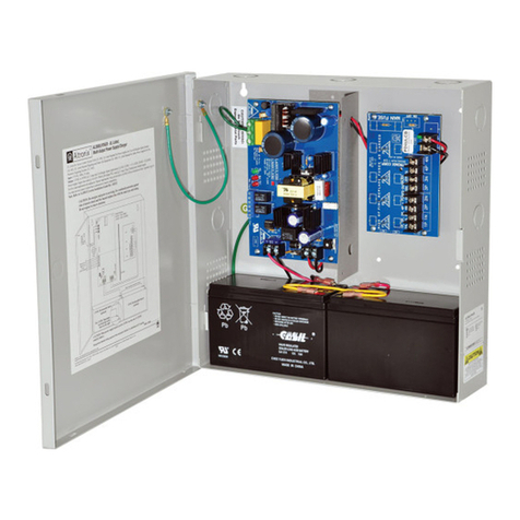
• Unit is complete with power supply and enclosure.
• Includes battery leads.
Enclosure Dimensions (H x W x D approx.):
8.5” x 7.5” x 3.5” (215.9mm x 190.5mm x 88.9mm).
Overview:
Altronix AL100UL power supply converts 16.5VAC, 20VA to a 12VDC power-limited output (see specifications).
The AL100UL is UL Listed for Burglar Alarm applications.
Specifications:
Stand-by Specifications:
Stand-by Battery Current Draw Stand-by Time Alarm Time
12VDC / 4AH Battery 750mA 4 Hours 15 mins.
Installation Instructions:
Wiring methods shall be in accordance with the National Electrical Code/NFPA 70/NFPA 72/ANSI, and with all
local codes and authorities having jurisdiction. Product is intended for indoor use only.
1. Mount the unit in the desired location. Mark and predrill holes in the wall to line up with the top two keyholes
in the enclosure. Install two upper fasteners and screws in the wall with the screw heads protruding. Place the
enclosure’s upper keyholes over the two upper screws; level and secure. Mark the position of the lower two
holes. Remove the enclosure. Drill the lower holes and install two fasteners. Place the enclosure’s upper
keyholes over the two upper screws. Install the two lower screws and make sure to tighten all screws
(Enclosure Dimensions, pg. 4). Secure enclosure to earth ground (Fig 1, pg. 2).
2. Connect a 16.5VAC, 20VA Class 2, UL Listed plug-in transformer to the terminals marked [AC, AC] (Fig 1, pg. 2).
3. Measure output voltage before connecting devices. This helps avoiding potential damage.
4. Connect devices to be powered to the terminals marked [– DC +] (Fig 1, pg. 2).
5. Connect the stand-by battery to the terminals marked [– BAT +] (Fig 1, pg. 2) (battery leads included).
6. Connect appropriate signaling notification devices to the AC Fail and Low Bat supervisory relay outputs
terminals marked [LOW BAT - NC, C, NO, AC FAIL - NC, C, NO] (Fig 1, pg. 2).
Note: To meet UL requirements, AC Supervisory outputs must be connected to the zone of Alarm Control
Panel or to visual AC trouble indicator.
Note: For Access Control applications batteries are optional.
When batteries are not used, a loss of AC will result in the loss of output voltage.
When the use of stand-by batteries is desired, they must be lead acid or gel type.
LED Diagnostics:
Red (DC) Green (AC) Power Supply Status
ON ON Normal operating condition.
ON OFF Loss of AC. Stand-by battery supplying power.
OFF ON No DC output.
OFF OFF Loss of AC. Discharged or no stand-by battery. No DC output.
AL100UL Installation Guide - 3 -
Maintenance:
Unit should be tested at least once a year for the proper operation as follows:
Output Voltage Test: Under normal load conditions the DC output voltage should be checked for proper
voltage level (Stand-by Specifications Chart).
Battery Test: Under normal load conditions check that the battery is fully charged, check specified
voltage both at the battery terminal and at the board terminals marked [– BAT +] to
ensure that there is no break in the battery connection wires.
Note: Maximum charging current under discharge is 500mA.
Note: Expected battery life is 5 years; however, it is recommended changing batteries in
4 years or less if needed.
Terminal Identification:
Terminal Legend Function/Description
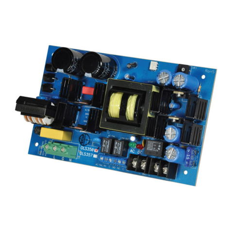
AC/AC Low voltage AC input (16.5VAC/20VA). UL Listed. Class 2 plug-in transformer.
– DC + 12VDC @ 750mA continuous power-limited output.
– BAT + Stand-by battery connections. Maximum charge rate 500mA.
AC FAIL
NC, C, NO
Indicates loss of AC, e.g. connect audible device or alarm panel. Relay is normally
energized when AC power is present. Contact rating 1A @ 28VDC.
LOW BAT
NC, C, NO
Indicates low battery condition e.g connect audible device or alarm panel.
Relay is normally energized. Contact rating 1A @ 28VDC.
AC DC
AC FAIL
LOW BAT
RL2
RL1
PTC1
IC1
C1
NO C NC
NO C NC
Class 2
Output
16.5VAC, 20VA
Plug-in Transformer
(UL Listed Class 2
Transformer)
750mA 12VDC
Power-Limited Output
Stand-by
Battery
Fig. 1
- 4 - AL100UL Installation Guide
Altronix is not responsible for any typographical errors.
––––––––––––––––––––––––––––––––––––––––––––––––––––––––––––––––––––––––––––––––––––––––––––––––––––––––––––––––
140 58th Street, Brooklyn, New York 11220 USA | phone: 718-567-8181 | fax: 718-567-9056
website: www.altronix.com | e-mail: [email protected] | Lifetime Warranty
IIAL100UL F29U MEMBER
7.25” (184.2mm)
3.625” (92mm)
1.25”
(31.8mm)
3.5” (88.9mm)
6.05” (153.7mm)
1.125”
(28.6mm)
1.125”
(28.6mm)
0.6” (15.2mm)0.6” (15.2mm)
2” (50.8mm)2” (50.8mm)
8.125” (206.4mm)
1”
(25.4mm)
1”
(25.4mm)
1”
(25.4mm)
1.25”
(31.75mm)
1.25”
(31.75mm)
1”
(25.4mm)
1”
(25.4mm)
5.25” (133.35mm)
6.05” (153.7mm)
3.5” (88.9mm)
Enclosure Dimensions (H x W x D):
8.5” x 7.5” x 3.5” (215.9mm x 190.5mm x 88.9mm)
The lightning flash with arrowhead symbol within an equilateral triangle is intended to alert the user
to the presence of an insulated DANGEROUS VOLTAGE within the product’s enclosure that may be of
sufficient magnitude to constitute an electric shock.
The exclamation point within an equilateral triangle is intended to alert the user to the presence of impor-
tant operating and maintenance (servicing) instructions in the literature accompanying the appliance.
CAUTION: To reduce the risk of electric shock do not open
enclosure. There are no user serviceable parts inside. Refer servicing
to qualified service personnel.

Other Altronix Power Supply manuals

Altronix ALTV129-DC User manual

Altronix

Altronix ALTV129-DC User manual

Altronix AL300ULX User manual

Altronix

Altronix AL300ULX User manual

Altronix eFlow3NB User manual

Altronix

Altronix eFlow3NB User manual

Altronix T1CVK3F4 User manual

Altronix

Altronix T1CVK3F4 User manual

Altronix TROVE T1RM3F4D User manual

Altronix

Altronix TROVE T1RM3F4D User manual

Altronix ULXB Series User manual

Altronix

Altronix ULXB Series User manual

Altronix AL600ULX Series User manual

Altronix

Altronix AL600ULX Series User manual

Altronix AL175UL User manual

Altronix

Altronix AL175UL User manual

Altronix WayPoint562 User manual

Altronix

Altronix WayPoint562 User manual

Altronix ALTV248UL3 series User manual

Altronix

Altronix ALTV248UL3 series User manual

Altronix SMP7 User manual

Altronix

Altronix SMP7 User manual

Altronix ALTV2432300UL3 User manual

Altronix

Altronix ALTV2432300UL3 User manual

Altronix AL176220 Series User manual

Altronix

Altronix AL176220 Series User manual

Altronix AL300X220 User manual

Altronix

Altronix AL300X220 User manual

Altronix LPS3C24X User manual

Altronix

Altronix LPS3C24X User manual

Altronix SMP7PM User manual

Altronix

Altronix SMP7PM User manual

Altronix ALTV2432220 Series User manual

Altronix

Altronix ALTV2432220 Series User manual

Altronix ALTV2416ULX User manual

Altronix

Altronix ALTV2416ULX User manual

Altronix Maximal Fit Series User manual

Altronix

Altronix Maximal Fit Series User manual

Altronix T1MK14 User manual

Altronix

Altronix T1MK14 User manual

Altronix TROVE DMP 734 User manual

Altronix

Altronix TROVE DMP 734 User manual

Altronix SMP7 User manual

Altronix

Altronix SMP7 User manual

Altronix OLS250 User manual

Altronix

Altronix OLS250 User manual

Altronix ALTV1224DC220 Series User manual

Altronix

Altronix ALTV1224DC220 Series User manual

Popular Power Supply manuals by other brands

Velleman LABPS5005 user manual

Velleman

Velleman LABPS5005 user manual

Valcom VPB-260 user guide

Valcom

Valcom VPB-260 user guide

Conrad 752227 operating instructions

Conrad

Conrad 752227 operating instructions

Whelen Engineering Company UPS158 installation guide

Whelen Engineering Company

Whelen Engineering Company UPS158 installation guide

Gigabyte ODIN Pro 1200W Features

Gigabyte

Gigabyte ODIN Pro 1200W Features

AGRO ELECTRO DL 3200 user manual

AGRO ELECTRO

AGRO ELECTRO DL 3200 user manual

Antec NeoPower 550 user manual

Antec

Antec NeoPower 550 user manual

CAMBRIONIX TS3-C10 user manual

CAMBRIONIX

CAMBRIONIX TS3-C10 user manual

Smart-Fly PowerExpander Sport user guide

Smart-Fly

Smart-Fly PowerExpander Sport user guide

CARLO GAVAZZI XAP10RSEXX Configuration manual

CARLO GAVAZZI

CARLO GAVAZZI XAP10RSEXX Configuration manual

EFLOW eFlow 104N Series installation guide

EFLOW

EFLOW eFlow 104N Series installation guide

EEZ H24005 Building instructions

EEZ

EEZ H24005 Building instructions

Pulsar DING2 Series user manual

Pulsar

Pulsar DING2 Series user manual

Bren-Tronics BTE-70791A-T1B Operation manual

Bren-Tronics

Bren-Tronics BTE-70791A-T1B Operation manual

Crystal Vision Indigo PSU-75i user manual

Crystal Vision

Crystal Vision Indigo PSU-75i user manual

Avansa PREMIUM 300W/500VA-12VDC user manual

Avansa

Avansa PREMIUM 300W/500VA-12VDC user manual

Kikusui PAT20-200T user manual

Kikusui

Kikusui PAT20-200T user manual

Keysight e3620a Operating and owners manual

Keysight

Keysight e3620a Operating and owners manual

manuals.online logo
manuals.online logoBrands
  • About & Mission
  • Contact us
  • Privacy Policy
  • Terms and Conditions

Copyright 2025 Manuals.Online. All Rights Reserved.