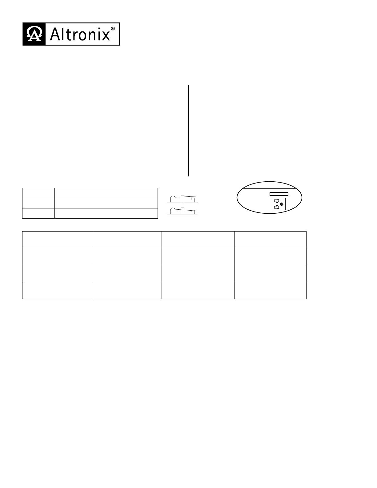
Power Supply Voltage Output Selections:
Output Switch Position
12VDC SW1 - CLOSED (Fig. 1, on right)
24VDC SW1 - OPEN (Fig. 1, on right)
Stand-by Specifications:
Output 4 hr. of Stand-by &
5 Minutes of Alarm
24 hr. of Stand-by &
5 Minutes of Alarm
60 hr. of Stand-by &
5 Minutes of Alarm
12VDC / 40AH Battery Stand-by = 2.5 amp
Alarm = 2.5 amp
Stand-by = 1.0 amp
Alarm = 2.5 amp
Stand-by = 300mA
Alarm = 2.5 amp
24VDC / 12AH Battery -------- Stand-by = 200mA
Alarm = 2.5 amp --------
24VDC / 40AH Battery Stand-by = 2.5 amp
Alarm = 2.5 amp
Stand-by = 1.0 amp
Alarm = 2.5 amp
Stand-by = 300mA
Alarm = 2.5 amp
Installation Instructions:
The AL300XB2V should be installed in accordance with article 760 of The National Electrical Code or NFPA 72
as well as all applicable Local Codes.
1. Mount the AL300XB2V in the desired location/enclosure.
2. Set the AL300XB2V to the desired DC output voltage by setting SW1 (Fig. 2, pg. 2) to the appropriate position
(refer to Power Supply Voltage Output Selections chart).
3. Connect AC power (220VAC 50/60Hz) to the terminals marked [L, G, N] (Fig. 2, pg. 2). Use 18 AWG or larger for all
power connections (Battery, DC output, AC input). Use 22 AWG to 18 AWG for power-limited circuits
(AC Fail/Low Battery reporting).
Keep power-limited wiring separate from non power-limited wiring (220VAC 50/60Hz Input, Battery Wires).
Minimum 0.25” spacing must be provided.
CAUTION: Do not touch exposed metal parts. Shut branch circuit power before installing or servicing equipment.
There are no user serviceable parts inside. Refer installation and servicing to qualified service personnel.
4. Connect devices to be powered to the terminals marked [+DC –] (Fig. 2, pg. 2).
5. Measure output voltage before connecting devices. This helps avoiding potential damage.
6. For Access Control applications batteries are optional. When batteries are not used, a loss of AC will result in the
loss of output voltage. When the use of stand-by batteries is desired, they must be lead acid or gel type.
Connect battery to the terminals marked [+ BAT –] (Fig. 2, pg. 2). Use two (2) 12VDC batteries connected in series
for 24VDC operation (battery leads included).
7. Connect appropriate signaling notification devices to AC FAIL & BAT FAIL (Fig. 2, pg. 2) supervisory relay outputs.
Note: When used in fire alarm, burglar alarm or access control applications, “AC Fail” relay should be utilized to
visually indicate that AC power is on. To delay report for 6 hours cut “AC Delay” jumper (Fig. 2a, pg. 2).
AL300XB2V
Power Supply/Charger
Input Rating:
• Input220VAC50/60Hz,1.7amp.
Output Rating:
• 12VDCor24VDCselectableoutput.
• 12VDCor24VDC@2.5ampcontinuous
supply current.
• Filteredandelectronicallyregulatedoutput.
Battery Backup:
• Built-inchargerforsealedleadacidorgeltypebatteries.
• Maximumchargecurrent0.7amp.
• Automaticswitchovertostand-bybatterywhenACfails.
• Zerovoltagedropwhenswitchedovertobatterybackup.
Visual Indicators:
• ACinput,DCoutputandBatteryLEDindicators.
Supervision:
• ACfailsupervision(form“C”contacts).
• Lowbatteryandbatterypresencesupervision
(form “C” contacts).
Additional Features:
• Shortcircuitandthermaloverloadprotection.
Board Dimensions (W x L x H approximate):
4.5”x7.1” x1.44”(114.3mmx180.34mmx36.58mm).
OPEN SWITCH
CLOSED SWITCH
Switch Detail
+DC ---
NC C NO NC C NO
+ BAT ---
AC DC Bat
Risk of Fire,
Replace Fuses
As Marked
Opened - 24V
Closed - 12V
AC FailBat Fail
J1
SW1
5A 250V
15A 250V
AC Delay
15
L G N
Fig. 1
Overview:
The AL300XB2V is a power supply/charger that converts a 220VAC 50/60Hz input into a 12VDC or 24VDC output
(see specifications).
Specifications:


