Overview:
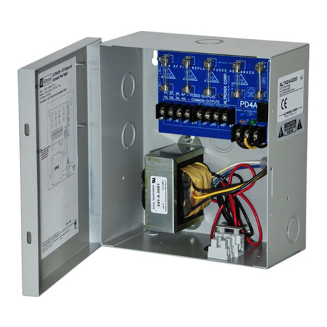
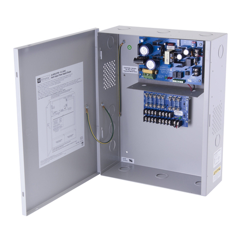
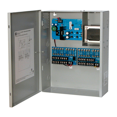
These Altronix CCTV Power Supplies provide 24VAC distributed via four (4) fuse or PTC protected outputs for
powering CCTV Cameras, heaters and other video accessories.
Four (4) Output ALTV244 Reference Chart:
ALTV244 4 amp 24VAC 4 - x 3.5 amp 5 amp/250VA .9 amp
ALTV244CB 4 amp 24VAC 4 x - 2.5 amp - .9 amp
ALTV244175
7.25 amp 24VAC 4-x3.5 amp 10 amp/250VA 1.5 amp
6.25 amp 28VAC
ALTV244175CB
7.25 amp 24VAC 4x-2.5 amp - 1.5 amp
6.25 amp 28VAC
ALTV244300 12.5 amp 24VAC 4-x3.5 amp 25 amp/250VA 2.7 amp
10 amp 28VAC
ALTV244300CB 12.5 amp 24VAC 4x-2.5 amp - 2.7 amp
10 amp 28VAC
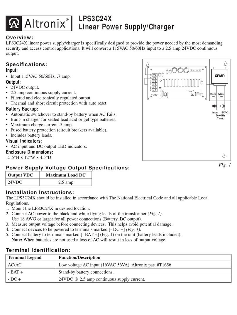
Specifications:
•Surge suppression. • Spare fuses included (on fuse protected models).
•AC power LED indicator. Enclosure Dimensions:
•Power ON/OFF switch ALTV244, ALTV244CB, ALTV244175,
•Unit maintains camera synchronization. ALTV244175CB, ALTV244300 and ALTV244300CB
•Ease of installation saves time & eliminates costly labor. 8.5”H x 7.5”W x 3.5”D
Installation Instructions:
1. Mount unit in desired location.
2. Slide switch SW1 to OFF position (Models ALTV244 and ALTV244CB), (Fig. 1, pg. 3). Turn off main switch on all
other models.
3. All units are factory set for 24VAC operation.
For 28VAC operation (for models with 24VAC/28VAC option only), adjust unit prior to mounting and applying
power as follows: Change the wire position so that the black wire [28V] is connected to the terminal marked [P] and
the yellow wire [24V] is connected to the terminal marked [S].
4. Connect AC power to the two black and two white flying leads of the transformer (Fig. 1, pg. 3). Use 18 AWG or
larger for all power connections (Battery, AC output).
Keep power limited wiring separate from non-power limited wiring (115VAC 50/60Hz Input, Battery Wires).
Minimum .25” spacing must be provided. Use separate knockouts.
5. Measure output voltage before connecting devices. This helps avoid potential damage.
Te r minals marked [1P - 4P] are positive (+) and terminals marked [1N - 4N] are negative.
CAUTION: Determine the maximum operating voltage of the equipment being powered before adjusting the
output voltage.
6. Connect devices to terminals marked [1P - 1N through 4P - 4N] on PD4/PD4CB board (Fig. 1, pg. 3) carefully
observing correct polarity.
Altronix
Model Number
Output Current
(max per output)
Total Output Current
(Power)
Output Voltage
115VAC
50/60Hz Input
Current
PTC Protected
Outputs
Fuse Protected
Outputs
- 2 -
Number of
Outputs
Main Fuse Ratings
