Alula BAT WIFI User manual

alula.net
BAT WIFI
SKU: IPD-BAT--WIFI
Wi-Fi & Internet
Alarm Communicator
PRODUCT MANUAL

1
Product Manual
BAT WIFI

2
QUICK REFERENCE
Programming for TELCO use on GE NetworX:
Section Device 0 Universal WiFi BAT as Sole Communicator
Location 0 Enter the Phone Number
Location 1 Enter Account Number
Location 2 Enter ‘13’ for Contact ID
Programming for TELCO use on Vista:
Section Universal WiFi BAT as Sole Communicator
41 Enter Phone Number
43 Enter Account Number
193 Enter 1, 0. Enable to turn on Address 20
Programming for TELCO use on DSC:
Section Universal WiFi BAT as Sole Communicator
301 Enter Phone Number
310 Enter Account Number
350 Enter ‘03’ for Contact ID

3
Technical Support Information
For Technical Support, call toll free: (888) 88-ALULA
alula.net
www.alarmdealer.com
setup.alarmdealer.com - Mobile Friendly
Alula
1402 Heggen St.
Hudson, WI 54016
Table of Contents
Quick Reference ............................................................................................................................ 2
Getting Started.............................................................................................................................. 3
• Pre-Installation............................................................................................................... 3
• Installation Guide.......................................................................................................... 3
DSC Panel Wiring and Programming..................................................................................... 6
DSC PC-Link Connection ............................................................................................................ 7
• DSC Programming Charts.......................................................................................... 8
Honeywell Vista Panel Wiring and Programming ...........................................................10
• Honeywell Vista Programming Charts ................................................................ 11
GE Panel Wiring and Programming...................................................................................... 12
• GE Panel Programming Chart................................................................................. 12
Generic Alarm Panel Wiring and Programming............................................................... 13
Supported Panels Charts ......................................................................................................... 15
Specications ............................................................................................................................... 17

4
Pre-Installation
Hardware Registration
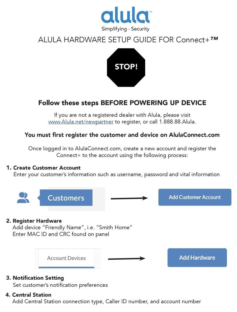
Before installation of your BAT-WIFI, it must be registered at www.alarmdealer.com.
Here are the steps needed to register your hardware:
• Log into www.alarmdealer.com with the dealer login information that was emailed to you.
• Click Create Account Wizard
• Follow the 4-Step Wizard
Installation Guide
General Considerations
• Before installation, your BAT-WIFI must be setup using the dealer branded portal www.alarmdealer.com.
• The BAT-WIFI should be installed securely in the supplied plastic housing, and be mounted beside your
alarm control panel.
• Where available, proximity to the hard-wired Ethernet Internet connection should be taken into
consideration when routing wires.
• Choose a location with good reception by monitoring the BAT- WIFI signal strength LEDs with a
pre-wire power up.
• The BAT-WIFI must be completely powered down before starting the wire up.
• Programming is simple using the alarm control panel. Written instructions are included in the
“Wiring & Programming” section of this manual.
AP Conguration Tool QuickStart Guide
An easy to use QuickStart Guide has been designed to make the BAT WiFi easily join the customer’s WiFi
Network.
Connecting to a Wireless Network (AP Conguration)
The BAT-WIFI has an AP Conguration Tool which is designed to assist with ensuring the BAT-WIFI joins a
wireless network easily.
The following steps should be followed:
1. Power up the BAT-WIFI at the alarm panel.
2. Open your smartphone or laptop and search for Wireless Connections
a. In the list of WiFi connections you should see one labeled: IPD-CFG-AP-XX-XX-XX. The last six digits
will match the MAC address of your WiFi device. If not, try moving your BAT-WIFI to a dierent
location for better reception.
3. Connect to the WiFi Network: IPD CFG-AP-XX-XX-XX
4. After you are connected to your smartphone or laptop. Open a web browser and type in the following IP
Address: 192.168.100.1
5. Once you have connected to the above IP Address it will launch the AP Conguration Tool.
6. Next you will click on “Scan for Wireless Networks”. This will populate a list of all available wireless
networks in your area.
7. Find the customers Wireless Network and click on it. If security credentials are required, you will be
prompted to enter them.
8. You should now be connected to the customers WiFi Network!

5
Connecting to a Wireless Network (WPS)
Press the SW1 button (located on the top left side of the board) once, this will send the device into WPS mode.
LED 6 will continue to blink as long as the unit is in WPS mode. Follow the router’s directions to turn WPS on
for it. Typically, enabling WPS involves simply pressing a button labeled ‘WPS’. Once the WiFi device and the
router see each other, LED 6 will go solid indicating it has found a network. You can now press the SW1 button
twice to see the signal strength of the unit.
Board Button Conguration
SW1 Button [located on the top left of the board]
There are many uses for the SW1 button and your WiFi device. You can tap on the button from 1 to 4 times
depending on what the situation is:
1 Tap – The BAT WIFI will go into WPS mode and search for nearest WPS activated WiFi
router in the area.
2 Taps - The BAT WIFI will update the signal strength [Device must be paired to a WiFi]
3 Taps - The BAT WIFI device will factory reset and lose connection to any WiFi it was previously
attached to.
4 Taps – The BAT WIFI will force a rmware upgrade [Device must be paired to a WiFi router]
Reset the Wireless Network (AP Conguration Tool)
Locate the button labeled SW1 on the top left of the board. When this button is pressed 3 times in a row, it
causes the device to perform a software reset and will allow you to perform the “AP Conguration Tool” again.
Locating and Installing the BAT-WIFI
The BAT-WIFI connects to the alarm panel’s power connections, Telco, virtual keypad bus (if available), and
keyswitch connections (optional).
The BAT-WIFI automatically seeks an IP address. There is no need to program routers or switches.
Telco - Digital Dialer
The BAT-WIFI’s signal collection expects Contact ID format from the digital dialer on the alarm panel. Most
control panels made in the last decade are CID capable. Wire the Telco side of the alarm control's Tip & Ring to
the BAT-WIFI Tip & Ring.
Virtual Keypad Connection
The BAT-WIFI connects to most panels as a Virtual Keypad. This allows the customer full virtual keypad
access after they authenticate using the customer username and password you have assigned them in the pre-
installation phase. You will need to refer to the wiring diagram for your specic panel because on the panel side
the Virtual Keypad connection has various labels (Data in-Data out, YEL-GRN, or just Data). This connects to
the G/RX, Y/TX connections on the BAT-WIFI.

6
Power Connection
The last step is to wire the alarm panel’s 12VDC auxiliary power and ground to BAT-WIFI positive (pin 3) and
negative (pin 4) terminals.
Basic Programming
Because the BAT-WIFI simulates telephone service to the panel, general programming for the control is limited
to conguring the signal format as Contact ID, as well as inputting a telephone number to dial. In this case the
actual telephone number does NOT matter and is NOT used in the signal delivery process.
When using Alula mobile and web interfaces, customers can enter their 4 digit code to arm & disarm the system.
For panels that are “Interactive Ready” the following programming will give you full Virtual Keypad access:
DSC Panels: No programming required to make the virtual keypad operate.
Vista Panels: Enable *193 with (1,0) to turn on Address 20.
GE Panels: Automatically enroll to Keypad Slot (Expansion 240) once you enter and exit programming.
Troubleshooting Diagnostic Information
Under normal operation the Activity light will periodically blink. A power cycle is recommended if the Activity
light is NOT periodically blinking.
LED – 1
• Used for DHCP & Network connection diagnostics:
• Solid: Indicates a connection has been made to Alula. (The unit is Online)
• 3 Flashes: Indicates the device is not connected to the Internet or is not pulling a DHCP from the router.
• 7 Flashes: Indicates the device is still working on “AP Conguration”, therefore is not connected to a
WiFi Network.
LED – 2
• Used to indicate signal transmission
LED – 6 (When not connected to a WiFi Router)
• Flashing: Indicating it’s searching for a router in WPS Mode.
• Solid: Indicates it found a router via WPS Mode.
LEDs – 3 to 6 (When connected to a WiFi Router)
• Display Signal Strength, which is updated on Startup and once every 4 hours.

7
Validating the Installation
After the unit is properly connected to the Alarm Panel and powered up, use the following steps to validate that
the system is functioning properly:
• Ensure that virtual keypad functionality works through www.alarmdealer.com,
www.setup.alarmdealer.com, or the Alula mobile app.
• Ensure that alarm signals reach your central station.
Wiring & Programming for Popular Panels
The following pages are organized by Alarm Panel type. Wiring and programming instructions are given for:
• Digital Security Control (DSC) Alarm Panels
• Honeywell Vista Alarm Panels
• GE NetworX Alarm Panels

8
DSC Keybus & Tip/Ring Wiring
DSC Panel Wiring and Programming

9
DSC PC-Link connection
This allows for remote downloader functionality with Alula’s Universal Downloader (uDownloader) software.
DSC PC-Link Wiring

10
DSC Panel Programming
See Supported Panels section on page 24. All Control Panels must have a Phone Number in the Panel and an
Account Number in the Panel. As long as your Reporting Codes are in the Panel and are transmitting in Contact
ID it will send signals.
Programming when using TELCO (Recommended): General Concept Programming on DSC (BAT WIFI as Sole
Communicator):
Section BAT as Sole Communicator Code Summarization
301 Enter a Receiver Number
310 Enter Account Number
350 Enter ‘03’ to send Contact ID Panel default is ‘04’, SIA
Note: Ensure All Report Codes are in, and signals can be sent.
Programming ONLY when using PC-Link to send Signals (Not Recommended): DSC Programming for
Communications - GSM Emulation:
If GSM is used, it must be in dialer capture mode
Section BAT as Sole
Communicator
BAT as Fail over
w/Add'l Communication
Device
BAT as Dual Reporting
w/Add'l
Communication Device
Code Summarization
015 Disable Option 7
If GSM, Disable Option
7 If Phone Line, Enable
Option 7
If GSM, Disable Option
7 If Phone Line, Enable
Option 7
Option 7 turns on/
o telephone line
supervision.
167 Set ‘060’ Seconds Set ‘060’ Seconds Set ‘060’ Seconds
Sets T-Link
acknowledgment delay
to 60 secs.
301 Set 'CAAF' Set 'CAAF' Set 'CAAF'
'CAAF' has to be set for
the panel to send signals
to the PC- Link
302 N/A N/A Set 'Central Station
Receiver #'
Second telephone
number goes here.
303 N/A Set 'Central Station
Receiver #'
Set 'Central Station
Receiver #'
This section is the
telephone backup of
section 301.
350 Set ‘04’ / ‘04’ Set ‘04’ / ’03 for Contact
ID, 04 for SIA FSK’ **
Set ‘04’ / ’03 for Contact
ID, 04 for SIA FSK’ **
Format sent as either
contact ID (03), or SIA
FSK (04). The PC-Link /
BAT can ONLY receive
signals via SIA FSK (04).

11
Programming ONLY when using PC-Link to send Signals (Not Recommended): if GSM is used, it must be in
dialer capture mode
Section BAT as Sole
Communicator
BAT as Fail
over w/Add'l
Communication
Device
BAT as Dual
Reporting w/Add'l
Communication
Device
Code Summarization
351 Enable Option 1 Enable Option 1, 5 Enable Option 1, 2, 5
Options to turn on/o alarm/
restore for telephone 1 (option
1), telephone 2 (option 2), and
alternate communications
(option 5).
359 Enable Option 1 Enable Option 1, 5 Enable Option 1, 2, 5
Options to turn on/o tamper/
restore for telephone 1 (option
1), telephone 2 (option 2), and
alternate communications
(option 5).
367 Enable Option 1 Enable Option 1, 5 Enable Option 1, 2, 5
Options to turn on/o
opening/closing for telephone
1 (option 1),telephone 2
(option 2), and alternate
communications (option 5).
375 Enable Option 1 Enable Option 1, 5 Enable Option 1, 2, 5
Options to turn on/o
maintenance for telephone
1 (option 1), telephone 2
(option 2), and alternate
communications (option 5).
376 Enable Option 1 Enable Option 1, 5 Enable Option 1, 2, 5
Options to turn on/o testing
for telephone 1 (option 1),
telephone 2 (option 2), and
alternate communications
(option 5).
380 Enable Option 1 Enable Option 1, 5 Enable Option 1, 5
Option 1 turns on/o
communications. Option
5 turns on/o 3rd phone
number.
381 Disable Option 3,
Enable Option 5
Disable Option 3,
Enable Option 5, 6
Disable Option 3,
Enable Option 5, 6
Option 3 turns on/o code
reporting. Options 5 & 6
turns on/o communication
with phone lines 1, 3 & 2
respectively.
382 Enable Option 5 Enable Option 5 Enable Option 5 Option 5 enables/disables
T-Link/PC-Link.
389 Set ‘003’Seconds Set ‘003’Seconds Set ‘003’ Seconds
The time it will take to
periodically check for faults on
the T-Link/PC-Link.

12
Vista Keybus & Tip/Ring Wiring
Vista Panel Wiring and Programming

13
Vista Panel Programming
All Control Panels must have a Phone Number in the Panel and an Account Number in the Panel. As long as
your Reporting Codes are in the Panel and are transmitting in Contact ID it will send signals.
Programming when using TELCO (Recommended): Programming on Vista (BAT WIFI as Sole Communicator):
Section For BAT as Sole
Communicator Code Summarization
41 Enter Phone Number
43 Enter Account Number
49 Enter 5 For All Communications to BAT
54 Enter 0 No Delay Between Communicators
55 Enter 0 Phone Line Communicates First
65 & 66 Enter 1 If you want Opening/Closing Reports
193 Enter 1, 0 Enable to turn on Address 20
Programming when ONLY using Keybus to send Signals (Not Recommended): Vista Programming for
Communications - GSM Emulation:
Section For BAT as Sole
Communicator
For BAT in use with
another Communication
Device for Fail over
For Dual Reporting Code Summarization
*29 Enter 1 Enter 1 Enter 1 This enables GSM. The
BAT Emulates a GSM.
*42 N/A Enter Central Station
Receiver Number
Enter Central Station
Receiver Number
Secondary Phone
Number.
*43 Enter Account Number Enter Account Number Enter Account Number This is the central station
account number.
*49 Enter 5
Please refer to panel
manual for your
particular application
requirements
Please refer to panel
manual for your
particular application
requirements
Dual Reporting; Setting
to 5 sends all reporting
to both primary and
secondary.
*54 Enter 0 Enter 2 Enter 0
The time it takes for
the communicator to
switch from primary to
secondary.
*55 Enter 1 Enter 1 Enter 1 (BAT is Primary
Communicator)
Setting to 1 gives signal
priority to GSM (BAT).
*65 Enter 1 Enter 1 Enter 1 Report Code for
Openings.
*66 Enter 1, 1 Enter 1, 1 Enter 1, 1 Report Code for Arming
in Away and Stay.
*193 Enter 1, 0 Enter 1, 0 Enter 1, 0
1 turns on/o keypad
address. 0 sets sound to
beep.

14
GE Keybus & Tip/Ring Wiring
GE Panel Programming
Recommended: General Concept Programming on GE NetworX:
Section BAT as Sole Communicator Code Summarization
Device 0,
Location 0 Enter the Phone Number
Device 0,
Location 1 Enter Account Number
Device 0,
Location 2 Enter ‘13’ Recommended value Contact ID
GE Panel Wiring and Programming

15
Generic Alarm Panel Wiring and Programming
Generic Keybus & Tip/Ring Wiring
Generic Alarm Panel Programming
• Program the panel Phone Number into the panel
• Program the Customers Account Number into the panel
• Program Reporting codes into the panel
• Program panel to transmit in Contact ID format
For interactive (Keyswitch) wiring and programming see the next section.

16
Generic Keyswitch Wiring and Programming
For basic keyswitch interactive services with the BAT WIFI, the following alarm panel wiring is needed:
• A programmable output on the alarm panel will be used to signal to the BAT (Y/Tx terminal) that
the panel has entered Arm/Disarmed State.
• The Z1 output on the BAT WIFI will be used as a keyswitch connecting to a ‘zone’ terminal on the
alarm panel.
*A pull up resistor may be required between terminal 3 to 5 to determine correct arm & disarm state.

17
Generic Keyswitch Programming
Examples for Ademco, Digital Security Controls, and GE NetworX for keyswitch and panel state program output
operations, as well as Keyswitch state programming are given below.
Most alarm panel manufacturers will have the capability to congure a zone as a keyswitch and generally have
at least one on-board programmable output that can be congured to activate on a number of dierent control
state conditions. Reference the alarm panel installation manual for details on your specic installation.
Ademco (Typical)
• 56 program zone as type 77
• 80 Menu LED Outs
• Program 17 and 18 zone type 78 and 79
DSC PowerSeries (Typical)
• Section 001 - Zone must be programmed as a 22
• Section 009 - 05
DSC Alexor (Typical)
Wiring:
• Terminal 5 -> I/01
• Terminal 15 -> I/02
• 6.2k ohms resistor from Terminal 3 -> Terminal 5
Programming:
• Section 009 - '05'/'22'
• Section 013 - Enable 2 & Disable 1
• Section 134 - Enable 14 (Press 9, then 6)
• Section 206 - Enable Option 2
• Section 501 - Enable 3
GE NetworX (Typical)
• Device ‘0’ Location 25, press * until you reach desired zone
• Program zone as '11'
• LED Status Device ‘0’
• Location 47 Segment 1: 21
• Location 47 Segment 2: 0

18
Supported Panels
Honeywell
Panel Revision Digital Dialer Full Interactive GSM Emulator
Vista-10P 2.6+ ✓✓✓
Vista-10PSIA 4.0+ ✓✓✓
Vista-128BP 3.0+ ✓✓✓
Vista-128BPE 1.0+ ✓✓✓
Vista-128FB 1.0+ ✓✓✓
Vista-128FBP 2.0+ ✓✓✓
Vista-128FBPE 1.0+ ✓✓✓
Vista-128SIA 2008+ ✓✓✓
Vista-15 2+ ✓✓✓
Vista-15CN 2.6+ ✓✓✓
Vista-15P 2.6+ ✓✓✓
Vista-15PCN 2.6+ ✓✓✓
Vista-15PSIA 4.0+ ✓✓✓
Vista-20P 2.6+ ✓✓✓
Vista-20PCN 2.6+ ✓✓✓
Vista-20PI 5+ ✓✓✓
Vista-20PS 2.6+ ✓✓✓
Vista-20PSIA 4.0+ ✓✓✓
Vista-21IP 1.0+ ✓✓✓
Vista-21IPSIA 1.0+ ✓✓✓
Vista-32FB 1.0+ ✓✓✓
First Alert FA130 2.6+ ✓✓✓
First Alert FA148 2.6+ ✓✓✓
First Alert FA168 2.6+ ✓✓✓
ADT Safewatch Pro
3000/3000EN 2.6+ ✓✓✓
DSC (Digital Security Control)
Panel Revision Digital Dialer Full Interactive GSM Emulator
PC5010 Any ✓✓✓
PC1616 4.13+ ✓✓✓
PC1832 4.13+ ✓✓✓
PC1864 4.13+ ✓✓✓
Alexor ALL ✓✓✓
*Not ALL virtual keypad features may work. Arm/Disarm/System Status do work.

19
GE NetworX
Panel Revision Digital Dialer Full Interactive GSM Emulator
NX-4V2 V2+ ✓✓✓
NX-6V2 V2+ ✓✓✓
NX-8V2 V2+ ✓✓✓
Note: Any Panel not on the supported lists above should function properly as long as it transmits Contact ID
through Tip & Ring. If the panel has the ability to use a Dedicated Open Zone that acts as a Keyswitch you can
Arm/Disarm from the Website or Mobile Phone.
For non-supported panels: Bridge 12 VDC to "Y/TX" Terminal with any type of radial resistor with a value of
2.7k to 10k as a weak "pull up".
Table of contents
Other Alula Security System manuals

Alula
Alula RE603P Instruction Manual

Alula
Alula Connect+ RE6100P-XX-X DKIT User manual

Alula
Alula Connect+ User manual

Alula
Alula RE251 Hidden Panic User manual

Alula
Alula RE626 User manual

Alula
Alula RE116-U User manual

Alula
Alula RE103P Instruction Manual

Alula
Alula RE617 User manual

Alula
Alula Connect+ User manual
Popular Security System manuals by other brands

Samsung
Samsung SMO-152QN - Monitor + Camera 4 user guide

Bosch
Bosch UEZ Operation manual

Patlite
Patlite NE-SN-USB instruction manual

Menvier Security
Menvier Security TS2500 Operator's manual

Federal Signal Corporation
Federal Signal Corporation 27XL-024-4 Installation and maintenance instructions

Swann
Swann PRO-681 user manual