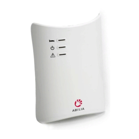
Abilia All In One User manual


3
All In One
EN User manual 4
NO Brukerhåndbok 30
SE Bruksanvisning 56

54
Find your way around the manual
All In One is available with various accessories that require individual
installation.To nd the right section in the user manual, remove all products
from their packaging and check them against the descriptions below.
All In One basic conguration Go to page 12
Pager with power cord Transmitter
Find the right model
All In One with module for wireless alarm Go to page 10
Pager with power cord Transmitter with power cord
All In One with GSM module Go to page 7
Pager with power cord Transmitter with power cord Antenna
Contents
Chapter 1: Install transmitter
6Transmitter overview
7Install SIM card
8Link transmitter to mobile phone
9Key to alarms on mobile phone
10 Pair wireless alarm unit
12 Fit transmitter
13 Connect sensors to transmitter
Chapter 2: Install Pager
14 Pager overview
15 Install pager
16 Pair transmitter to pager
17 Key to pager signals
Chapter 3: Maintenance
18 System test and replacing batteries
19 Handling and cleaning
Chapter 4: Troubleshooting and other information
20 Troubleshooting
22 Technical information
24 Personalised label in pager
25 Important information
Contents
EN

76
Test button
Battery
compartment
Status indicator
Removable cover
Sensor 1 Sensor 2
Power supply Sensor 3
GSM antenna
Wireless alarm
indicator
SIM card port
GSM indicator
Install SIM card
With a GSM module, you can also receive alarms on a mobile phone, very
practical when you are out of the building. You will need a Micro SIM card
for the transmitter (not a prepaid card). The SIM card shall either have the
PIN set to code '0000' or have no PIN code, see the operator's instructions
to change PIN code.
How to install a SIM card
Note:Disconnectthe transmitterfromitspowersupply wheninstallingaSIMcard.
1Attach the GSM antenna and pull out the battery tab on the transmitter.
2Open the cover and remove the batteries. Insert the SIM card into the
holder in the battery compartment marked with a symbol. The
symbol indicates card direction.
3Reinstall the batteries and close the lid. Connect the power cord to the
transmitter and plug into a mains socket.
When the transmitter is connected to the GSM network, the status indicator
light will ash green every 15 seconds. If it does not start ashing green
within 2 minutes, go to Troubleshooting on p. 20.
123
If the indicator is It means that
Flashing every 3 s • ThetransmitterisconnectedtotheGSMnetwork.
Constantly lit • The transmitter is texting and calling an assistant.
Flashing every 1 s • ThetransmitterhaslostcontactwiththeGSMnetwork.
O • The transmitter has no GSM module/ it’s out of order.
GSM indicator light
Thetransmitter hasanindicator light, showing currentGSM status,locatedinside
the cover and marked with a symbol (see overview on left). This indicates
whetherthe transmitteris linkedtothe GSMnetworkand whenit is transmitting.
Chapter 1 Install transmitter.Chapter 1 Install transmitter.
Transmitter overview
EN

98
Link transmitter to mobile phone
To receive alarms via GSM, the transmitter must be linked to the assistant's
mobile phone. A transmitter can handle up to two assistants. They are
designated Assistant 1 and Assistant 2.
How to link a transmitter
1Send a text message with Assistant 1’s number to the transmitter’s mobile
number according to the principle below. Repeat for Assistant 2.
2To test the link: press the transmitter's test button. The transmitter will
send a text message and call the assistants in the order stated on the
next page. If no text or call is received, see Troubleshooting on page 20.
Repeat steps 1-2 to link a new transmitter. Send the message with the
mobile numbers of the assistants to the new transmitter’s mobile number.
A1 A2
123
Chapter 1 Install transmitter.
How to read alarms
1To quickly be able to see which transmitter is sending an alarm, you need to
enter a contact in your mobile contact list for each transmitter on the system.
Note: Name the transmitter according to the resident's name or room number.
2When a sensor is activated on any of the transmitters, you will receive a
text message with the following:
Transmitter name (or mobile number if it’s not in your address book)
Activated sensor no. 1-4
The example below shows that sensor 1 in Ebba's room has activated.
Chapter 1 Install transmitter.
How it works
1When a sensor is activated, the transmitter sends an alarm via text mes-
sage to Assistant 1. As a safety precaution, it also makes a call (tone only).
2Assistant 1 has 20 seconds to respond to the call. To prevent confusion
with voice mail, the call has to be concluded within 10 seconds.
3If Assistant 1 fails to answer or hang up in time, the text message and call
are redirected to Assistant 2.
Q W E R T Y I O P Å
A S D F H J K L Ö Ä
Z X C V B N M
ALERT
0704313335
A1
12
Assistant 2
ALERT 'MOBILE NUMBER' A2
For example:
ALERT 070123456789 A2
Assistant 1
ALERT 'MOBILE NUMBER' A1
For example:
ALERT 070123456789 A1
Ebba
Sensor 1
activated
Arne
Ola Ann
Ebba
Note: You can switch assistant by texting the new number to the transmitter
according to the ALERT 'NEW MOBILE NUMBER' A1 principle.To clear all assis-
tant numbers, text DELETE to the transmitter.This action cannot be cancelled.
Note: Use space before and after the mobile number.
EN

1110
Pair wireless alarm unit
A wireless alarm unit is often carried on the wrist or around the neck, but also
comes in the form of a wireless door and movement sensor. The wireless alarm
unit needs to be paired to the transmitter before it can work with the system.
Linking a wireless alarm unit
1Pull out the battery tab to start the transmitter. Connect power cord and
plug into a mains socket.
2Press and hold the transmitter's test button. Release the button when
the transmitter's status indicator light begins to ash blue.
3Activate the alarm unit within 10 seconds to pair the units.The transmitter
status indicator light will ash green three times when ready.
Repeat steps 2-3 to link a new alarm unit. Max. 4 units can be linked.
If the LED is It means that
Lit / blinks in yellow • The transmitter is receiving an alarm / heartbeat.
Lit in orange • Thetransmitterisreadytobeconnectedtothealarmunit.
O • The transmitter has no wireless alarm module.
• Themoduleisoutoforder.
Indicator light for wireless alarm unit
There is an indicator under the cover that shows the current alarm status. It
is marked with a symbol (see Overview on p. 6). Here you can see if the
alarm unit is linked and when the transmitter receives an alarm.
123
Chapter 1 Install transmitter.
Delete wireless alarm units
1Press and hold the transmitter's test button. Release the button when
the transmitter's status indicator light begins to ash blue.
2Press the transmitter test button three times in quick succession.
3The transmitter's status indicator will show that all linked alarm units
have been deleted by ashing green twice.
Note: This action deletes pairings permanently and cannot be cancelled.
3
1
x3
x2
2
Chapter 1 Install transmitter.
EN

1312
Important! Mount at least
1.5 m from the caretaker.
Mounting a transmitter
Note: A transmitter with a GSM module or wireless alarm unit needs a
certain amount of preparation before mounting.
Before installing a transmitter with GSM module,read page 7-9.
Beforeinstallinga transmitterwith, wireless alarm unit module,readpage 10.
How to mount a transmitter
1Pull out the battery tab to start the transmitter.
2Mark and then drill the holes using the drilling template.
3Leave 2mm distancebetween screw headand wallwhen screwing thescrews
in. Hang the transmitter on the wall and check that it is securely in place.
Repeat steps 1-3 to mount a new transmitter.
Ф5.5mm
123
1 2 3
Chapter 1 Install transmitter.
Red diode is for
wireless alarm unit
and test button.
Connect sensors to transmitter
You can connect up to 3 dierent wired sensors to a transmitter, e.g.
epilepsy alarm, incontinence alarm and door sensor.
How to connect a sensor
1Connect the sensor on the under side of the transmitter according to
the gure below. Select input for SENSOR 1 or SENSOR 2 if it has an
RJ11 jack and input for SENSOR 3 if it has a 3.5 mm mono telephone
jack. Check that the jack is securely in place and that the cable is secure.
2Verify that the connection works by activating the sensor. The status
indicator light will ash yellow to show that an alarm has been sent.
Repeat steps 1-2 to connect a new sensor.
Note: Each sensor is allocated its own LED light on the pager as follows:
SENSOR 1 - Orange diode
SENSOR 2 - Green diode
SENSOR 3 - Yellow diode
The red diode is reserved for wireless alarm unit and test button.
IfyouhaveinstalledSEVERAL transmitters,the pagerwillsignaldierently, seep.17.
Note: Detailed information on how to install and use the various sensors
can be found in the respective sensor's user instructions.
If the LED is It means that
Blinking in green • Thesystemisworkingnormally.
Blinking in yellow • The transmitter is activated by a sensor and sending an alarm.
Blinking in red • Thetransmitter’sbatterylevelislow,seep.18.
Blinking in purple • Thebatteriesarettedincorrectly/wrongtype,seep.18.
Blinking in white • TheGSMmoduleissearchingnetworkoroutoforder,seep.20.
Blinking in blue • Thewirelessalarmunitisreadytobeconnected/error,seep.20.
Transmitter status indicator light
The indicator light on the front shows the current status. It can for instance
tell you when the transmitter sends an alarm or if an error has occurred.
Note: If an error occurs, check the indicator lights located under the cover.
EN

1514
Transmitter
error
No coverage
Sound On/O
Low pager
battery
Acknowledge
button
Charging indicator
Bed vibrator
test button
Power
indicator
Bed vibrator
outlet
Bed vibrator
(accessory)
Replaceable
label
Sensor 1
Transmitter 1
Sensor 2
Transmitter 2
Sensor 3
Transmitter 3
Wireless alarm and test button
Transmitter 4
Chapter 2 Install pager.
Overview of pager and charger
”click”
1
2
Chapter 2 Install pager.
How to use the pager
When a sensor is activated, the pager will sound and vibrate.The diode col-
our and ashing pattern shows which transmitter/sensor has been activated.
If you want to Do this
Switch o the pager alarm • PressthepagerAcknowledge button.
Mute the alarm • Push the pager Sound switch up/down.
Switch the pager on/o • Push the pager On/O switch right/left.
EN
Install pager
1Pull out the battery tab on the pager and charger to start the units.
2Plug the charger into a mains socket. The power LED will light up to
show that it is connected. Place the pager in the charger and check that
it clicks into place. The charging LED will blink/light up to show that
it’s charging.
Note: Remember to charge the pager for 6 hours before using it for the rst
time. When fully charged, the charging LED will turn o.

1716
Pair transmitter to pager
1To link a transmitter, press and hold the pager acknowledge button.
Release the button when the two centre diode lights start to ash.
2Press the transmitter test button within 10 seconds to pair the units.
3Adiode light on the pagerwill come on toshow that the transmitteris linked:
Orange diode - Transmitter 1 Yellow diode - Transmitter 3
Green diode - Transmitter 2 Red diode - Transmitter 4
1 2 3 4
123
Repeat steps 1-3 to link a new transmitter. You can link up to 4 units.
Delete linked transmitter
1Press and hold the pager OK button until the two centre diodes begin
to ash. Press the button three times in quick succession.
2All the diodes will ash twice to show that the linked transmitters have
been deleted. This action cannot be cancelled.
Chapter 2 Install pager.
Activated transmitter Activated sensor Colour and ashing pattern
Transmitter 1 Sensor 1 Orange
Transmitter 1 Sensor 2 Green
Transmitter 1 Sensor 3 Yellow
Transmitter 1 Wireless alarm unit Red
Transmitter 1 Test button Red
Activated transmitter Activated sensor Colour and ashing pattern
Transmitter 1 Sensor 1 Orange
Transmitter 1 Sensor 2 Orange
Transmitter 1 Sensor 3 Orange
Transmitter 1 Wireless alarm unit Orange
Transmitter 1 Test button Orange
Transmitter 2 Sensor 1 Green
Transmitter 2 Sensor 2 Green
Transmitter 2 Sensor 3 Green
Transmitter 2 Wireless alarm unit Green
Transmitter 2 Test button Green
Transmitter 3 Sensor 1 Yellow
Transmitter 3 Sensor 2 Yellow
Transmitter 3 Sensor 3 Yellow
Transmitter 3 Wireless alarm unit Yellow
Transmitter 3 Test button Yellow
Transmitter 4 Sensor 1 Red
Transmitter 4 Sensor 2 Red
Transmitter 4 Sensor 3 Red
Transmitter 4 Wireless alarm unit Red
Transmitter 4 Test button Red
Key to pager signals
The pager shows which sensor and transmitter has activated by using various
diode colours and ashing patterns.
Note: The pager diode colours and ashing pattern dier depending on
whether you have ONE or SEVERAL transmitters linked to the system.
System with ONE transmitter - Each sensor has a dedicated diode colour
System with - Each transmitter has a dedicated diode colour
SEVERAL transmitters - Sensors are identied by ashing pattern
Chapter 2 Install pager.
12
EN

1918
Changing batteries
Check battery performance regularly on all units to ensure that the system
is fully functional. Please note that rechargeable NiMH batteries should be
replaced approx. every 2 years. Always keep batteries out of reach of children.
Dispose of batteries according to your local environmental laws and guidelines.
Replacing batteries in the transmitter
Open the cover of the transmitter. Remove the old batter-
ies and replace with new ones. Instructions are above the
battery compartment.
Important! If the transmitter is battery powered,
use alkaline AAA batteries only. If the transmitter
is mains powered, use rechargeable NiMH AAA
batteries only. NEVER mix NiHM batteries with alkaline
batteries as the batteries and charger can overheat.
Replacing batteries in the pager
Open the battery cover on the back of the pager. Remove
the old battery and replace with a new one, see the
instructions in the battery compartment.
Important! Only rechargeable NiMH AAA
batteries shall be used in the pager.
Replacing batteries in the pager charger
Open the battery cover under the pager charger. Remove
the old batteries and replace with new ones. Instructions
are in the battery compartment.
Important! Only rechargeable NiMH AAA
batteries shall be used in the pager charger.
Chapter 3 Maintenance. Chapter 3 Maintenance.
System test
It is important that system function is checked at least once a week. Perform
a full system test to include activating all sensors and test all transmitter
alarm functions.
Important!
More frequent test intervals can be required if specied by the sensor
user manual.
More frequent test intervals may be required in special circumstances, if
the system conguration is modied or if any of the units are dropped.
Handling and cleaning
Warning! Failure to follow the instructions for handling and cleaning
can damage the products and void the warranty.
Using jacks and outlets
Always check that the jack ts the connector and that it is correctly aligned.
Never force a jack into a connector. If it is dicult to plug in the jack, check
that the connector is not blocked in any way and make sure that you are
plugging it into the right connector.
Using the products
Do not use or store the products near a source of heat. Only use in dry
environments when the temperature is between 15°-35° C. Do not use
the pager in the bath or shower. If the pager or transmitter gets wet or is
exposed to moisture, it should no longer be regarded as reliable and should
be replaced. If you do not plan to use the product for an extended period,
remove the batteries.
Cleaning
Before cleaning the product, disconnect it from any power source. Use a
soft, lint-free cloth. Avoid any moisture getting into the openings. Never use
window cleaner, detergents, sprays, solvents, alcohol, ammonia or products
that contain abrasives.
Guarantee and service
If the product is either damaged or out of order, follow the instructions in
the user manual. If the product continues to function incorrectly, contact
your local dealer for details on guarantee cover and service.
Other important information
Information on how to dispose of the product and other important
information on instructions and safety can be found in the section on
Important information on p. 28-29.
© and TM 2015 Bellman & Symfon AB. All rights reserved. Bellman and Bellman & Symfon
are registered trade marks owned by Bellman & Symfon AB.
EN

2120
If Try this
Transmitter status
indicator light
ashing red
• Thetransmitter battery level is low. Replace the
batteries if the transmitter is battery powered.
Charge the batteries if it is mains powered.
Important!
If the transmitter is battery powered,
use alkaline AAA batteries only. If the
transmitter is mains powered, use rechargeable
NiMH AAA batteries only. NEVER mix NiMH
batteries with alkaline as the unit can overheat.
Transmitter status
indicator light
ashing purple
• Batteriesintransmitterarewrongtypeor
tted incorrectly. See above for correct
conguration and tting of batteries.
Transmitter status
indicator light
ashing white
• The GSM module is indicating an error. Open
the cover and check the GSM LED above the
-symbol (see Transmitter overview on p 6).
• If the LED is blinking every second, no GSM
network has been detected. Check that the SIM
card is tted correctly and that you have GSM
coverage in your area, see Installing a SIM card
on p 7.
When the transmitter is connected to a GSM
network the GSM LED will blink every 3 s.
• If the problem persists, contact your GSM
provider.
• If the LED is o, the unit has no GSM module
or the module is out of order. Contact your
dealer for service.
Transmitter status
indicator light
ashing blue
• Thetransmitter is ready to be connected to a
wireless alarm unit.
• Thealarmunitisfaulty,seeseparateuser
manual. If the problem persists, contact your
dealer for service.
Chapter 4 Troubleshooting and other information.
Troubleshooting
Most problems with the system can be quickly solved by following the
instructions below.There are more tips and information on troubleshooting
on our website.
Transmitter
Chapter 4 Troubleshooting and other information.
If Try this
Pager cannot be charged • Checkthatthepageriscorrectly
placed in the charger. The LED by the
-symbol will blink/light up to show that
it’s charging.
• Checkthatthechargerisconnectedto
mains power. The LED by the -symbol
is lit to show that it is connected. If the
LED blinks, it is using the backup battery.
Reserve battery in charger
not working and charger
symbol o
• Checkbatteriesarecorrectlyttedand
charged. Charge or replace batteries,
see Changing batteries on p. 18.
Pager charger
If Try this
Pager symbol is
lit whilst the pager is
vibrating and beeping
• Pagerhaslostradiocontactwithatrans-
mitter. The LED position on the pager will
indicate which transmitter is at fault if you
have several transmitters. Move to within
range of the transmitter.
Pager symbol is lit
whilst the pager is
vibrating and beeping
• Atransmitterinthesystemisindicating
an error. The LED position on the pager
will indicate which transmitter is at fault
if you have several transmitters. See
Troubleshooting transmitter on p. 20.
Pager symbol is white,
whilst the pager is
vibrating and beeping
• Pagerhaslessthantwohoursofbatterylife
left. Charge batteries by putting the pager
in its charger. A full charge takes 6 hours.
Pager symbol is red,
whilst the pager is
vibrating and beeping
• Batteryinpageriswrongtype,incorrectly
tted or at. Check how the battery is tted
or replace, see Changing batteries on p. 18.
Pager not emitting any
sound whilst the
symbol is lit
• Pagersoundswitchedo.Slidesound
switch upwards to restore sound. Switch is
on right side of pager (see overview).
Pager
EN

2322
Technical information
All In One Transmitter
Dimensions and weight h140mmx w105mm xd 30mm,210 gincl.batteries
Mains electricity Input: 100 - 240 V ~ 50/60 Hz 0.3 A
Output: 7.5 V 1000 mA
Use the supplied adaptor model
SSA-10W-12 EU 075100 by SIL
Batteries With mains electricity: 4 x 1.2 V AAA rechargeable
NiMH batteries. Use the supplied rechargeable
batteries model HFR-AAA900 900 mAh by
Shenzen Highpower Technology Co. Ltd., or
model 5703 1000 mAh by Varta. Without mains
electricity: 4 x 1.5V AAA alkaline batteries.
Operating time 365dayswithout GSMmodule or wirelessalarm unit
4hreservewith GSM module or wireless alarm unit
Electricity consumption 0.3 mA in basic conguration
Connections 1 x 7.5V power cord
2 x RJ-11 inputs
1 x 3.5 mm tele jack
1 x SMA jack for GSM antenna
Activation Via test button
Via sensors connected to the 3 sensor inputs
Via wireless alarm unit (module BE9230 required)
Radio frequency 869.2375 MHz
Range Up to 500 m line of sight. The range is reduced
by walls and large objects that obstruct radio sig-
nals.The range can also be aected by other radio
transmitters such as TVs, PCs, mobile phones or
tablets.
Environment For indoor use only
Temperature range: 15° - 35° C
Relativeair humidity: 5 to95%, non-condensating
Shall be installed at least 1.5m from the caretaker
Regulatory Fulls WEEE, CE, RoHS and R&TTE
Accessories BE9220 Module for GSM
BE9230 Module for wireless alarm units
All In One Pager
Dimensions & weight h 91 mm x b 55 mm x d 23 mm, 60 g incl. battery
Battery power 1 x 1.2 V AAA rechargeable NiMH battery. Use the
supplied rechargeable battery model HFR-AAA900
900mAhby ShenzenHighpowerTechnology Co.Ltd.
Operating time 24 h
Charging time Up to 6 h
Electricity consumption 20 mA
Activation Via radio
Radio frequency 869.2375 MHz
Range Up to 500 m line of sight. The range is reduced by
wallsand largeobjects thatobstruct radiosignals.The
rangecan alsobe aectedbyother radiotransmitters
such as TVs, PCs, mobile phones or tablets.
Environment For indoor use only temperature range: 15° - 35° C
Relative air humidity: 5 to 95%, non-condensating
Regulatory Fulls WEEE, CE, RoHS and R&TTE
All In One pager charger
Dimensions & weight h110mm xw 93mmx d110mm, 195g incl.batteries
Mains power Input: 100-240V~50/60Hz 0.5A,
Output: 7.5V 1600mA. Use the supplied adaptor
model SFP0751600P made by Helms-Man.
Battery power 4 x 1.2 V AAA rechargeable NiMH batteries. Use the
supplied rechargeable batteries model 80AAAHC
800 mAh by GP.
Power consumption 200 mA
Connections 7.5V power cord
3.5 mm tele jack for bed shaker
Activation Via the test button that activates a bed shaker
Environment For indoor use only.Temperature range: 15° - 35° C
Relative humidity: 5% - 95%, non-condensing
Regulatory Fulls WEEE, CE, RoHS and R&TTE
Accessories BE1270 Bed shaker
Chapter 4 Troubleshooting and other information. Chapter 4 Troubleshooting and other information.
EN
CAUTION! Explosion hazard if battery is replaced by an incorrect type.
Dispose of used batteries according to the recycling instructions.

2524
Personalised label in pager
A personalised label makes it easier to identify alarms on your pager.
Depending on conguration, you can write the name of residents or the
sensors linked. An extra label is included in the package.
Replacing labels in the pager
1Remove the transparent plastic coverprotecting the panel with coloured
diodes. Avoid damaging the plastic.
2Replace the label.
3Snap the plastic cover back into place.
Note: You can download and editable PDF version on our website.
”click”
12
3
Chapter 4 Troubleshooting and other information. Chapter 4 Troubleshooting and other information.
EN
Important information
This section contains important information about safety, handling, disposal,
recycling and warranty.
Read the manual and all safety information before using All In
One. Keep the manual for future use.
Warning!
• Thereisapotentialriskofre,electricalshock,ordamagetothe
product if the safety instructions are not followed.
• Donotuseorstorethisproductnearanyheatsourcessuchasradiators,
naked ames, ovens or any other heat output.
• Protectthecablesfromanypotentialsourceofdamage.
• Useonlythepowersupplyandaccessoriesspeciedinthismanual.
• Disconnectthepowersupplyfromthemainsduringthunderstormsorif
the product is not in use for a long period.
• Iftheproductisdroppedalwaystestitbeforereusing.
• Pleasenotethatthedeliberateoraccidentalswitchingoofthevolume
or power switch on the Pager can result in a missed alarm.
• Beawarethatalarmscanbemissedifbatteriesrunout,connectorsbecome
disconnected, or mobile systems are out of operation. Only refer damaged
or faulty products to qualied service personnel.
• Donotdismantletheproduct;thereisariskofelectricshock.Tampering
with or dismantling the product will void warranty.
• Theproductisintendedtobeusedasacarealertingsystembutshould
not be used as the only security in life-threatening situations.This product
does not replace the need for personal supervision of patients/users.
• Theproducthasnopowerswitch.Inordertodisconnecttheproduct,the
charger and power supply must be disconnected from the wall outlet.
Make sure that these are easily accessible.
• Theproductisdesignedforindoorsuseonly.
• Donotexposetheproducttomoisture.
• Protecttheproductfromshocksduringstorageandtransport.

2726 Chapter 4 Troubleshooting and other information. Chapter 4 Troubleshooting and other information.
EN
Model, type and classication
Information is available at the back of the All In One Pager and on the charger
for the Pager.
Recycling of old products
The symbol means that according to local laws and regulations it
should not be disposed of with household waste.When the product
is no longer of use, hand it in to a recycling centre for electrical waste
and electronic equipment. By recycling used products you will help to
conserve natural resources and protect health and the environment.
Recycling of used batteries
This symbol means that the product contains batteries that accor-
ding to local laws and regulations must not be disposed of with
household waste. Take used batteries to a battery disposal facility
or a recycling centre.
The European Union - declaration of conformity
Hereby, Bellman & Symfon Europe AB, declares that
this product is in compliance with the essential
requirements and other relevant provisions of R&TTE 1999/5/EC, LVD 2006/95/
EC, MDD 93/42/EEC and EMC 2004/108/EC directives. The declaration
of conformity may be consulted at Bellman & Symfon Europe AB, Södra
Långebergsgatan 30, 421 32 Västra Frölunda, Sweden.
0359

2928
Assistant 1
Name:
Mobile no:
Transmitter 1
Mobile no:
Sensor 1:
Sensor 2:
Sensor 3:
Wireless alarm:
Transmitter 2
Mobile no:
Sensor 1:
Sensor 2:
Sensor 3:
Wireless alarm:
Transmitter 3
Mobile no:
Sensor 1:
Sensor 2:
Sensor 3:
Wireless alarm:
Transmitter 4
Mobile no:
Sensor 1:
Sensor 2:
Sensor 3:
Wireless alarm:
Pagers
Orange diode:
Green diode:
Yellow diode:
Red diode:
Assistant 2
Name:
Mobile no:
My notes
Use the illustration below to note details of your installation
of the All In One system.
Note. Examples of notes include a reminder of which sensors
you have linked to the transmitter, which transmitter is linked
to the pager and contact details for assistants.
If you need more pages, go to our website for a PDF version
under My notes.
Chapter 4 Troubleshooting and other information. Chapter 4 Troubleshooting and other information.
EN

3130
Finn fram i brukerhåndboken
All In One kommer med tilbehør som krever forskjellige installasjoner. For å
nne frem til riktig avsnitt i brukerhåndboken må du derfor ta alle produkter
ut av forpakningen og sammenligne innholdet med beskrivelsene nedenfor.
All In One i grunnutførelse Gå til side 38
Pager med strømtilførsel Sender
Finn fram i brukerhåndboken.
All In One med modul for trådløs alarmenhet Gå til side 36
Pager med strømtilførsel Sender med strømtilførsel
All In One med GSM-modul Gå til side 33
Pager med strømtilførsel Sender med strømtilførsel Antenne
Innhold
Kapittel 1: Installere sender
32 Oversikt over sender
33 Installere SIM-kort
34 Koble sender til mobiltelefon
35 Tolke alarm på mobiltelefon
36 Koble til trådløs alarmenhet
38 Montere sender
39 Koble sensorer til sendere
Kapittel 2: Installere pager
40 Oversikt over pager
41 Installere pager
42 Koble sender til pager
43 Pagerens signalmønster
Kapittel 3: Vedlikehold
44 Systemtest og skifte batteri
45 Håndtering og rengjøring
Kapittel 4: Feilsøking og annen informasjon
46 Feilsøking
48 Teknisk informasjon
50 Tilpasse etikett i pageren
51 Viktig informasjon
Innhold.
NO

3332
Installere SIM-kort
Med en GSM-modul kan du ta imot alarm også på mobiltelefonen, noe som er
praktisk når du benner deg utenfor huset eller leiligheten.Til senderen trenger
du et kort av typen Micro SIM (ikke kontantkort). SIM-kortet skal ha pinkode
'0000'eller væreutenpinkode, seoperatørensanvisningerforendring avpinkode.
Slik installerer du et SIM-kort
Merk: Senderen må ikke være koblet til strøm ved installasjon av SIM-kort.
1Skru fast GSM-antennen og trekk bort batterilappen på senderen.
2Åpne lokket og ta ut batteriene. Sett SIM-kortet i holderen ved batterirom-
met som er merket med et -symbol. Symbolet viser kortets retning.
3Sett batteriene på plass og steng lokket. Koble strømtilførselen til sen-
deren og sett kontakten i strømuttaket.
Når senderen er koblet til GSM-nettet, blinker statusindikatoren grønt hvert
15 sekund. Hvis den ikke blinker grønt innen 2 min, se Feilsøking på s. 46.
123
Hvis indikatoren Betyr det at
Blinker hvert tredje sekund • SenderenerkoblettilGSM-nettet.
Lyser konstant • Senderen sender sms og ringer til assistent.
Blinker hvert sekund • SenderenharikkekontaktmedGSM-nettet.
Er slukket • Senderen mangler GSM-modul/er ute av funksjon.
Indikator for GSM
Senderen har en indikator som viser aktuell GSM-status. Den er plassert innen-
for lokket og er merket med et -symbol (se oversikt til venstre). Her kan du
f.eks. se om senderen er koblet til GSM-nettet og når den sender en melding.
Kapittel 1 Installere sender.
Oversikt over sender
Testknapp
Batterirom
Statusindikator
Avtakbart lokk
Sensor 1 Sensor 2
Strømtilførsel Sensor 3
GSM-antenne
Indikator for
trådløs alarm
Port for SIM-kort
Indikator
for GSM
NO

3534
Koble sender til mobiltelefon
For å kunne motta alarm over GSM må du koble senderen til assistentens
mobiltelefon. En sender kan håndtere opp til to assistenter. De tildeles
prolene Assistent 1 og Assistent 2.
Slik kobler du til en sender
1Send en sms med Assistent 1's mobilnummer til senderens abonnement
ifølge prinsippet nedenfor. Repeter fremgangsmåten for Assistent 2.
Merk: Mellomrom foran og etter mobilnummeret.
2For å teste tilkoblingen, trykk på senderens testknapp. Senderen sender da
sms og ringer opp assistentene i den rekkefølgen som beskrives på neste
side. Hvis ingen sms eller samtale går gjennom, se Feilsøking på s. 46.
Repeter trinn 1-2 for å koble til en ny sender. Husk å sende sms med
assistentenes mobilnummer til den nye senderens abonnement.
A1 A2
123
Kapittel 1 Installere sender.
Slik leser du av alarmen
1For at du enkelt skal se hvilken sender som sender alarm, må du opprette
en kontakt i mobiltelefonens adressebok for hver sender i systemet.
Tips! Navngi senderen etter f.eks. personens navn eller romnummer.
2Når en sensor aktiveres på en av senderne, får du en sms med følgende:
Senderensnavn(ellermobilnummerhviskontaktenikkennes i adresseboken)
Aktivert sensor nr. 1-3
I eksempelet nedenfor ser du at sensor 1 i Ebbas rom er aktivert.
Kapittel 1 Installere sender.
Slik fungerer det
1Når en sensoraktiveressendersenderen enalarm via smstil Assistent1. Som
etsikkerhetstiltakringer senderenogsåopp (kuntonerhøreshos mottakeren).
2Assistent 1 har 20 sek på seg til å svare på samtalen. For å forhindre
forveksling med telefonsvarer må samtalen avsluttes innen 10 sek.
3Hvis Assistent 1 ikke svarer eller ikke legger på i tide, sendes sms'en og
samtalen videre til Assistent 2.
Q W E R T Y I O P Å
A S D F H J K L Ö Ä
Z X C V B N M
ALERT
0704313335
A1
12
Assistent 2
ALERT 'MOBILNUMMER' A2
For eksempel:
ALERT 070123456789 A2
Assistent 1
ALERT 'MOBILNUMMER' A1
For eksempel:
ALERT 070123456789 A1
Ebba
Sensor 1
activated
Arne
Ola Ann
Ebba
Merk: Du bytter enkelt ut en assistent ved å sms'e det nye nummeret til
senderen ifølge prinsippet ALERT 'NYTT MOBILNUMMER' A1. For å erne alle
assistenters nummer, sms'e DELETE til senderen. Handlingen kan ikke angres.
NO

3736
Koble til trådløs alarmenhet
En trådløs alarmenhet bæres ofte på håndleddet eller rundt halsen, men
nnes også i form av trådløse dør- og bevegelsessensorer. For at den trådløse
alarmenheten skal fungere med systemet, må du koble den til senderen.
Slik kobler du til en trådløs alarmenhet
1Trekk bort batterilappen for å starte senderen. Koble til strømtilførselen
og sett kontakten i strømuttaket.
2Trykk og hold inne senderens testknapp. Slipp knappen når senderens
statusindikator begynner å blinke blått.
3Aktiver alarmenheten innen 10 sek for å parkoble enhetene. Senderens
statusindikator viser at det er klart ved å blinke grønt tre ganger.
Repetertrinn 2-3 forå koble tilen nyalarmenhet. Du kan koble til maks.4 stykker.
Hvis indikatoren Betyr det at
Lyser / blinker gult • Senderen tar imot alarmsignal / kontrollerer status.
Lyser oransje • Senderenerklartilåparkoblesmedalarmenheten.
Er slukket • Senderen mangler modul for trådløs alarmenhet.
• Modulen er ute av funksjon.
Indikator for trådløs alarmenhet
Senderen har en indikator som viser alarmenhetens status. Den er plassert
innenfor lokket og er merket med et -symbol (se Oversikt på s. 32). Her kan
du f.eks. se om alarmenheten er tilkoblet, og når senderen mottar en alarm.
123
Kapittel 1 Installere sender.
Slette trådløse alarmenheter
1Trykk oghold innesenderens testknapp forå slettetilkoblede alarmenheter.
Slipp knappen når senderens statusindikator begynner å blinke blått.
2Trykk tre ganger i rask rekkefølge på senderens testknapp.
3Senderens statusindikator viser at alle tilkoblede alarmenheter har blitt
slettet ved å blinke grønt to ganger.
Merk: Handlingen sletter tilkoblingene permanent og kan ikke angres.
3
1
x3
x2
2
Kapittel 1 Installere sender.
NO

3938
Viktig! Kan ikke monteres
nærmere enn 1,5 m fra pasienten
Ф5,5mm
Montere sender
Merk: Sender med modul for GSM eller trådløs alarmenhet krever en viss
forhåndsinstallasjon før montering.
For installasjon av sender med modul for GSM, les først sidene 33-35.
For installasjonav sender med modulfor trådløsalarmenhet, les førstside 37.
Slik monterer du en sender
1Trekk bort batterilappen for å starte senderen.
2Marker borehull ved hjelp av den vedlagte boremalen og bor hull for
medfølgende skrue og plugg.
3La det være 2 mm avstand mellom skruehode og vegg når du strammer til
skruene.Hengsenderenopp påveggenogkontrollerat densittertrygtpåplass.
Repeter trinn 1- 3 for å montere en ny sender.
123
1 2 3
Kapittel 1 Installere sender.
Rød lysdiode er for
trådløs alarmenhet
og testknapp.
Koble sensorer til sendere
Du kan koble til opp til 3 forskjellige kablede sensorer til en sender, f.eks.
epilepsialarm, inkontinensalarm og dørsensorer.
Slik kobler du til en sensor
1Koble til sensoren på undersiden av senderen ifølge guren nedenfor. Velg
inngangen for SENSOR 1 eller SENSOR 2 hvis den har en RJ11-kontakt, og
inngangen for SENSOR 3 hvis den har en 3,5 mm mono plugg. Kontroller
at kontakten sitter sikkert på plass og at kabelen sitter godt fast.
2Kontroller at tilkoblingen fungerer ved å aktivere sensoren. Status-
indikatoren på senderen blinker da gult for å vise at en alarm sendes.
Repeter trinn 1-2 for å koble til en ny sensor.
Merk: Hver sensor tildeles en egen lysdiode på pageren ifølge:
SENSOR 1 - Oransje lysdiode
SENSOR 2 - Grønn lysdiode
SENSOR 3 - Gul lysdiode
Rød lysdiode er reservert for trådløs alarmenhet og testknapp.
Hvis du har installert FLERE sendere, signaliserer pageren annerledes, se s 43.
Tips! Detaljert informasjon om hvordan du installerer og bruker de
forskjellige sensorene, nner du i den respektive sensors brukerhåndbok.
Hvis indikatoren Betyr det at
Blinker grønt • Systemetfungerersomdetskal.
Blinker gult • Senderen aktiveres av en sensor og sender alarm.
Blinker rødt • Senderenharlavtbatteri,ladoppellerskiftbatterier,ses.44.
Blinker lilla • Batterieneermontertfeil/avfeiltype,seSkifte batteri på s. 44.
Blinker hvitt • GSM-modulensøkeretternettellereruteavfunksjon,
se Feilsøking på s. 46.
Blinker blått • Klartilåkobletrådløsealarmenheten/feilalarmenhet,
se Feilsøking på s. 46.
Senderens statusindikator
Senderen har en indikator på forsiden som viser aktuell status (se Oversikt på s.
32).Her kan duse når senderensender en alarm eller om dethar oppstått en feil.
Tips! Hvis det oppstår en feil, løft lokket og se øvrige indikatorer for mer info.
NO
Table of contents
Languages:
Other Abilia Security System manuals
Popular Security System manuals by other brands

Genesys
Genesys Genesys 824 Alpha owner's manual

Dantel
Dantel B23-41071 Installation & operation manual

Endura
Endura DVR5300 Series Installation guidelines

Control Products
Control Products PhoneAlarm Series quick start guide

Honeywell
Honeywell SUGPACK-UK Quick installation guide

ANZ
ANZ DIGIPASS 276 user guide

Radionics
Radionics D205 user guide

Honeywell
Honeywell Galaxy 2-44+ quick start guide

Honeywell
Honeywell ADEMCO VISTA-10P Quick guide to user functions

Busch-Jaeger
Busch-Jaeger Busch-Infoline 1515 U operating instructions

Intermatic
Intermatic SP440B supplementary guide

Agri Alert
Agri Alert TP-800 user guide