Alula RE667 User manual

Connect Family
RE667 SlimlineTouchpad
The RE667 Slimline Touchpad is an intuitive interface
for controlling the security system. It is AC powered and
communicates with the panel wirelessly.
Features
•
Vibrant 7’’ Android™ tablet display
•
Provides local control of security and automation functionality
•
Wall or table mounted
•
Encrypted, Connect+ and BAT-Connect enabled, battery-backed
Wi-Fi™ connection
Installation Overview for Connect+
1.
Confirm the panel has a Wi-Fi DeviceLink card installed.
2.
Choose a mounting location. Touchpad can be mounted on a wall or tabletop.
3.
Identify your network and verify signal strength before mounting it permanently.
I
Installing the Wi-Fi DeviceLink Card
•
Disconnect the panel’s AC power and backup
battery.
•
Install the Wi-Fi DeviceLink card in Slot 2 by
carefully aligning the nylon retention posts and
the 8-pin connector while pushing the card
firmly until all posts are fully seated.
•
Reconnect the panel’s AC power and backup
battery.
•
Verify the Wi-Fi card LEDs are on.
AC
Power
Input
Slot
2
Backup
Battery
1.
Ensure the panel is powered.
2.
Power the Touchpad by applying AC power.
3.
Select the “Connect” option to see the available networks. If the “Connect” option is
not available, press “Setup” then “Factory Default”. The Touchpad can be connected
to either the Wi-Fi DeviceLink card or the home router for internet access. (Internet
access allows for camera control, weather updates, and the ability to modify users.)
4.
Once a network is determined, verify the signal strength. If the signal strength
displayed is less than 35, relocate the Touchpad or Connect+ panel. If neither options
are available, install an RE621 Touchpad Range Extender.
Note:
If connecting to a home network router, the Connect+ needs to be connected
to the same network via ethernet. The Touchpadcannot connect to the panel over an
unsecured or open network.

72DF
9EF8
By default the Touchpad network list will show Connect+ and BAT-Connect access points. To
view all networks in range tap the “Show all networks” button at the bottom of the network
list.
4.
Mount the Touchpad. Refer to section “Touchpad Mounting Options” for mounting
instructions.
5.
Enroll the Touchpad by pressing the enroll button on the side of the panel until it beeps
once and then select the desired network.
Note: If connecting to a home network, enter router credentials at the Touchpad. After a
connection is established, the Touchpad will discover all devices on the network. Select
the desired panel. After selecting the desired panel, the Touchpad will progress through
stages of discovery and authentication. Upon success it will show the DISARMED screen.
If the wrong panel was selected, press the “Restart”button in the side menu.
6.
If using cameras or user management features, you must log in to the Alula Cloud as
the account owner. To log in go to Settings and select Touchpad. Enter master code, then
select Alula Cloud. Sign in with your username and password.
Note: Internet access is required.
7.
Test the Touchpad by arming and disarming the panel from the Touchpad.
Troubleshooting Steps if Enrollment Fails:
•
Confirm the panel is disarmed and in wireless enrollment mode. A red light will flash on
the panel if in wireless enrollment mode.
•
Check whether the panel is already full. The limit is four Touchpads. To confirm number
of Touchpads connected, log into your account.
•
Tap the "Restart" button to tryagain.

Installation Overview for BAT-Connect
1.
Chose a mounting location. Touchpad can be mounted on a wall or tabletop.
2.
Identify your network and verify signal strength before mounting it permanently.
3.
Mount the Touchpad. Refer to section “Touchpad Mounting Options” for mounting
instructions.
4.
Enroll the Touchpad by pressing the enroll button on the BAT-Connect for 2-3 seconds. Select
your network, then select next. Enter the CRC of the BAT-Connect, which can be found on
the inside cover of the BAT-Connect.The Touchpad will progress through stages of discovery
and authentication. Upon success it will show the DISARMED screen. If the wrong device was
selected, press the “Restart”button in the side menu.
1.
Ensure the system is powered.
2.
Power the Touchpad by applying AC power.
Note:
The Touchpad cannot run off panel bus. Existing wiring needs to be moved to the
provided power adapter. For additional details, please refer to Wall Mounting section.
3.
Select the “Connect” option to see the available networks. The Touchpad should be
directly connected to the BAT-Connect access point. The Touchpad can access the
internet directly through the BAT-Connect.
Note: Internet access allows for camera control, weather updates, and the ability to
modify users.
4.
Once a network is determined, verify the signal strength. If the signal strength displayed
is less than 35, relocate the Touchpad or BAT-Connect.
Note: In order for the Touchpad to access the internet through the BAT-Connect access
point, the BAT-Connect must be connected via ethernet or Wi-Fi.
BAT - CONNECT - V
BAT - Connect, M1, VZ
MAC:123456005B14
Date: 19295
Patent Pending
~~
CRC:1234
Troubleshooting Steps if Enrollment Fails:
•
Confirm the system is disarmed and in wireless enrollment mode. The DeviceLink LED
on the BAT-Connect will flash when in enrollment mode.
•
If the “Connect” option is not available, press “Setup” then “Factory Default”.
•
Check whether the panel is already full. The limit is four Touchpads. To confirm number
of Touchpads connected, log into your account.
•
Tap the "Restart" button to tryagain.
•
BAT-Connect cover must be open for Enrollment Mode.

5.
If using camera or user management features, internet access is required. In order to access
the internet your BAT-Connect must be connected via ethernet or Wi-Fi. In addition you must
log in to the Alula platform using the account owner username and password. To log in go to
Settings and select Touchpad. Enter master code, then select Alula Cloud.
6.
Test the Touchpad by arming and disarming the system from the Touchpad.
Touchpad Mounting Options
Table Top Mounting
1.
Connect the power adapter by inserting the connector into the black port. Once inserted,
turn the connector to the right to lock into place.
2. Slide the Touchpad onto the stand.
The fit is intended to be quite snug, so some force may
be required for the stand to “click” into place.
3.
Coil up the excess power wire into the stand, and close the stand cover to contain the wires.
4.
Plug in powersupply.

Wall Mounting
1.
There are two mounting configurations.
A. If mounting on a stud, use the two centered holes labeled below [A].
B. If not mounting on a stud, use the four corner mounting holes. Insert the wall anchors prior
to screwing the screws in place [B].
A
BB
2.
There are two methods for connecting power to the Touchpad.
A. If you desire to hide the power cable, you can drill a hole in the wall through one of the
four windows in the mounting plate and pull a wire behind the drywall to a location with
an AC power outlet. Connect one end of the wire to the terminal block on the back of the
tablet. Push the buttons on the terminal block to allow the wire to be inserted. Splice the
other end of the wires to the power supply wires after cutting off the barrel jack. MUST USE
PROVIDED POWER SUPPLY. Power from an existing panel may be insufficient. Wire length
must not exceed lengths listed below.
WIRE
GAUGE
MAXIMUM LENGTH BETWEEN
POWER SUPPLY AND TABLET
#24
Up to 70 feet
#22
Up to 100 feet
#20
Up to 175 feet
#18
Up to 250 feet
#16
Up to 450 feet
B.
Barrel jack of the power supply
can be plugged directly into the back of the Touchpad.
Wires can be routed through wire channel in the back of mounting base. This configuration
requires the barrel jack be routed through the mounting base before the mounting base is
screwed to the wall.

3. Slide the Touchpad
onto the mounting plate.
Push any extra wire into
wall before sliding onto
mounting plate.
4.
Drop cover behind
Touchpad.
5.
Lock in cover by pressing
at these locations until
snapped into place.
6.
Plug in powersupply.
Menu Guide
Dashboard
•
Favorites - is a customizable collection of sensors, Z-Wave®devices, cameras, and
scenes that can be easily accessed from the TouchpadDashboard
Security
•
History - shows event history
•
Attention - shows all opened, bypassed, or troubled zones. Zones can be bypassed or
activated by pressing the toggle to the right of the zone name.
Note: Zone name and chime options can be edited by selecting a zone. User pin
authentication is required.
Devices
•
Add/Remove Z-Wave devices using the
“+
Add” or
“-
Remove” buttons in the app bar
•
Lock and unlock Z-Wave door locks
•
Configure Z-Wave door lock access codes
•
Turn Z-Wave lights on and off
•
Set dimmer level for Z-Wave dimmer switches

Devices (continued)
•
Open and close Z-Wave garage door openers
•
Control Z-Wave thermostats
**PLEASE SEE Z-WAVE USER GUIDE FOR ADDITIONAL INFORMATION**
Cameras
•
Cameras can be viewed directly from the Touchpad. Live view, clips, and event notifications
are supported. Doorbell live view will automatically be displayed when the doorbell button
is pressed. Internet access isrequired.
Scenes
•
Create scenes from the Touchpad by clicking the “+ Add” button
•
Enable/disable scenes with the toggle button
•
Navigate to the edit scene page by selecting an item in the list
•
Rename a scene by selecting the name label in the top bar
•
Modify the scene by adding/removing triggers and actions
More - System
•
Status
•
Troubles - shows all system troubles
•
If a system trouble condition exists, the panel will sound trouble beeps
•
To silence the trouble beeps for 24-hours:
•
Go to system page
•
Select the Silence button [upper right corner]
•
Smoke Reset - When a smoke detector needs to be reset it will appear here. Tap and
confirm to reset.
Note: This is supported for Napco panels. To reset smokes on all other panel types
navigate to Settings -> Panel -> Reset Sensors.
•
Status Updates - shows all status updates
•
Touchpad
•
Battery - shows battery level and charging information
•
Network - shows network the Touchpad is connected to
•
AccesspointMAC
•
Wi-Fi signal strength - must not be less than 35
•
Response Time
•
Wi-Fi channel
•
Touchpad Firmware
•
Touchpad Hardware
•
Updater Firmware
•
Serial Number
•
FCC/IC information
•
Uptime

More - Settings
•
Display
•
Brightness - adjust slide bar to change brightness level
•
Auto sleep display - when enabled the Touchpad screen will go to sleep after
programmed period of inactivity. When auto sleep is disabled, the Touchpad will show
wallpapers with time and arming level. Show Wallpaper shows/hides wallpaper images.
If disabled the background is black.
•
Entry wake - when enabled the screen will turn on during entry delay
•
Clean screen - ignores touch input on the screen for 30 seconds to allow user to clean
the screen
•
Sound
•
Voice Feedback - When enabled the Touchpad will announce system status updates.
The type of updates each Touchpad announces is configurable.
•
Chime - Allows chime on this specific Touchpad. You must enable the panel global
chime. This setting is used to disable chime on a per touchpad basis.
•
Media Volume - Controls voice feedback and doorbell notification volume.
•
Status & Keypress Volume
•
Security System Status Sounds
•
Keypress Sounds
•
Alarm Volume
•
Doorbell Tone - Select a custom doorbell notification tone.
•
Quiet Hours - Configure a time period where the Touchpad is quiet.
•
Touchpad (must enter code to access)
•
Show Favorites - display favorites menu that shows frequently used zones, scenes, and
devices on dashboard
•
Show Panics - ability to turn off individual panics (this option can only be viewed when
using installer or dealer code)
•
Lock to Dashboard
•
When enabled only the dashboard menu can be accessed without an access code
•
When disabled no access code is needed to navigate outside of dashboard
•
Return to dashboard - specifies time of inactivity before Touchpad will automatically
return to dashboard
•
Navigation - select which items should be accessible via the bottom navigation
•
Notifications - ability to turn on and off notifications on the system overview page
•
Wi-Fi - connect via Wi-Fi if using cameras and user management features
•
Temperature Scale - option for displaying °F or °C
•
Alula Cloud - must be logged into Alula Cloud as the account owner to use cameras
and user management features
•
Power Off

•
Panel (must enter code to access)
•
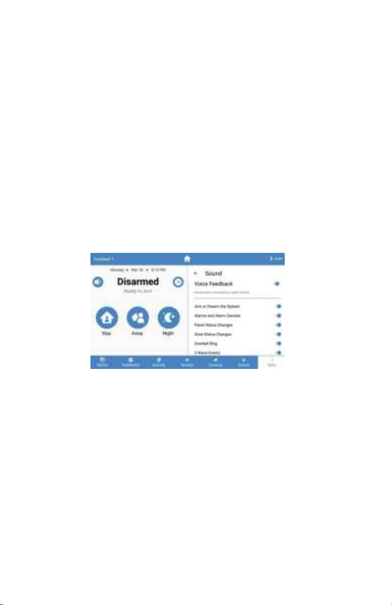
Global Chime - enables or disables panel sensor chime mode
•
Quick Arm - arm the panel without entering your access code. Access code is still
required to disarm.
•
Manage Access - manage device users directly from the touchpad (only the account
owner can modify users, internet access isrequired)
•
Edit Installer User - configure the system’s installer access code and password. The
installer password can be used to connect to a Connect+ panel via the Connect+
Installer app.
•
Dealer Code - configure the dealer code used by BAT-Connect to program the system
Note: Only available for Napco panels.
•
PushUserPinstoLocks-ifZ-Wavelocksarepresent,thiswilleraseallexistingaccess
codes from all door locks, and push all user pin codes to those locks. Pins will be
cropped to 4 digits before being programmed into the locks.
•
UL Compliant Mode - when enabled the Connect+ and BAT-Connect will adhere to UL
standards. Dealer or Installer authority is required to configure this option.
•
Keypads - lists the panel’s keypads
•
Rename keypads by selecting an item on the list and holding it for 2 seconds
•
Reset Sensor - when there are sensors that latch open, such as a smoke detectors, they
can be reset here.
•
Communication Test mode
•
The Touchpad will begin testing communications and display "TESTING"
•
After one minute, the Touchpad will show the result of the test which will be either
"GOOD," "FAIR," OR "POOR"
•
If you get a "POOR" test result, try the test again from another location
•
The table below lists the thresholds used to determine the outcome of the test
•
If any statistic falls in the poor range, the test outcome is "POOR"
•
If there are no poor statistics and any statistic is in the fair range, the outcome of
the test is "FAIR"
•
If all statistics are in the good range, the outcome of the test is "GOOD"
Statistic
Unit
GOOD
FAIR
POOR
Wi-Fi Signal
Strength
dB
Over 39
35 to 39
Under 35
Communication
Success Rate
%
Over 89
85 to 89
Under 85
Response Time
Average
ms
Under 200
200 to 250
Over 250
•
Check for updates - this will tell the panel to check for any system updates
•
Z-Wave
•
Join/Leave Another Z-Wave Network - the panel can be placed into Z-Wave
inclusion or exclusion mode to allow it to join/ leave existing Z-Wave networks.
•
Soft Reset - a soft reset will reset the Z-Wave controller software. All Z-Wave devices
will remain enrolled.
•
Hard Reset - this action will cause your Connect+ Z-Wave module to be restored
back to the default state. Warning: Performing this action results in all Z-Wave
devices being removed from this Z-Wave controller. To add them back, you will first
need to exclude them, and then include them again.
**PLEASE SEE Z-WAVE USER GUIDE FOR ADDITIONAL INFORMATION**
•
About - lists information about the panel’s installed hardware and software

Home Screen Functions*
The headline indicates panel statussuch as
“Disarmed” or “Armed Stay”
Tap to mute beeps
during arm/disarm
action
Tap to view Panic options
The time zone can be config-
ured on Alula Connect
Tap one of the arming buttons to
arm the panel
Tap to turn the Touchpad’s
display off
Tap to edit favorite zones,
device, scenes, and cameras
Tap to disable entry delay
Panic Functions*
Hold for three seconds to trigger police, fire, OR auxiliary alarm
Turn on/off individual
panics
*These features were taken from a Connect+. Your features may differ depending on panel.

Pro Tips
When a Touchpad is connected to the BAT-Connect or Connect+ through the DeviceLink
interface it remains available for use during momentary power outages. The BAT-Connect,
Connect+, and the DeviceLink connection are battery backed. If the Touchpad is connect-
ed only via the premise Wi-Fi, Alula recommends that all network equipment including
the Wi-Fi access point be connected to a suitable UPS to ensure system availability during
power outage. The Touchpad may and typically should be installed with both premise and
DeviceLink options, as it is designed to fall back to the DeviceLink interface during loss of
the premise Wi-Fi connection (for any reason).
Push any extra wire into wall before sliding Touchpad onto mounting plate to ensure
the wires don’t get pinched. Drill a hole in the wall through any of the 4 mounting plate
windows if no hole exists.
The Touchpad display turns off on its own after specified allotted time of inactivity
(Auto sleep display setting). It will turn back on when the screen is touched, or for some
alarm conditions. The screen can also be turned off manually by pressing "Sleep."
To unenroll the Touchpad navigate to the Settings menu and then to the section labeled
"Panel." Put the panel, or BAT-Connect, into wireless enrollment mode and press the
unenrollment button on the touchpad screen.
Note:
The unenroll button is displayed on the Touchpad only when the panel is in
enrollment mode.
Weather can be added
to the Touchpad if internet access is available. Toadd weather pull
down from the top of the screen and select the Add Weather option. Once a location is
configured live weather will appear in the pull-down menu or on the system overview screen
when the Auto Sleep Display setting is disabled.
To remove vanity cover, insert a flat head screwdriver at the two points shown below and twist
the screwdriver.

Specifications
Physical Specifications
Wall Dimensions
Table Top Footprint
Weight
Pilot Hole for Screw into Wood
Pilot Hole for Wall Anchor
Mounting Fasteners
4.27in[10.84cm] x 7.42in[18.85cm] x 1.60[4.06cm] Deep
4.58in[11.64cm] x 7.42in[18.85cm] x 6.63[16.84cm] High
1.29lbs[585g]
Ø 1/8in [3mm]
Ø 3/16in [4.7mm]
#6 screws & 4 wall anchors (included)
Environmental Specifications
Operating Temperature
Maximum Humidity
32°F to 120°F (0°C to 49°C)
85% non-condensing relative humidity
Device Specifications
Battery Life
Power Transformer
Input
Output
Part Number
Terminal Block Wire Gauge
Wireless Range
Screen Resolution
Screen Size
4 hours
100-240vac 50/60hZ 0.5A
12VDC, 1A
RE012-6
16-24 AWG
~300 feet in open air
1024 x 600 pixels
7 inches diagonally
Accessories
Wi-Fi DeviceLink
RE926RX (only needed for Connect+)
Certifications
RE667B, RE667W
FCC, IC, RCM
IC NOTICE
Specifications subject to change without notice.
This device complies with Industry Canada license-exempt
RSS standard(s). Operation is subject to the following two
conditions:
(1)
This device may not cause interference, and
(2)
This device must accept any interference, including
interference that may cause undesired operation of the
device.
Le présent appareil est conforme aux cnr d’Industrie
Canada applicables aux appareils radio exempts de licence.
L’exploitation est autorisée aux deux conditions suivantes:
(1)
L’appareil ne doit pas produire de brouillage, et
(2)
L’utilisateur de l’appareil doit accepter tout brouillage
radioélectrique subi, même si le brouillage est susceptible
d’en compromettre le fonctionnement.
TRADEMARKS
Alula and Connect+ are trademarks owned by Alula
Holdings, LLC. Android is a trademark of Google LLC.
Z-Wave is a registered trademark of Silicon Labs. Wi-Fi is a
trademark of The Wi-Fi Alliance.
FCC Statement
This equipment has been tested and found to comply with
the limits for a Class B digital device, pursuant to part 15 of
the FCC Rules. These limits are designed to provide
reasonable protection against harmful interference in a
residential installation. This equipment generates, uses
and can radiate radio frequency energy and, if not installed
and used in accordance with the instructions, may cause
harmful interference to radio communications. However,
there is no guarantee that interference will not occur in a
particular installation. If this equipment does cause harmful
interference to radio or television reception, which can be
determined by turning the equipment off and on, the user is
encouraged to try to correct the interference by one or more of
the following measures:
•Reorient or relocate the receiving antenna.
•Increase the separation between the equipment and receiver.
•Connect the equipment into an outlet on a circuit different
from that to which the receiver is connected.
•Consult the dealer or an experienced radio/TV technician for
help.
Caution: Any changes or modifications to this device not explicitly
approved by manufacturer could void your authority to operate this
equipment.
This device complies with part 15 of the FCC Rules. Operation is
subject to the following two conditions: (1) This device may not
cause harmful interference, and (2) this device must accept any
interference received, including interference that may cause
undesired operation.
Specific Absorption Rate (SAR) information:
This Communicator meets the government's requirements for
exposure to radio waves. The guidelines are based on standards
that were developed by independent scientific organizations
through periodic and thorough evaluation of scientific studies.
The standards include a substantial safety margin designed to

assure the safety of all persons regardless of age or health.
FCC RF Exposure Information and Statement the SAR
limit of USA (FCC) is 1.6 W/kg averaged over one gram of
tissue. Device types: Communicator has also been tested
against this SAR limit. This device was tested for typical
body-worn operations with the back of the phone kept
0mm from the body. To maintain compliance with FCC RF
exposure requirements,
useaccessories that maintain an 0mm separation distance
between the user's body and the back of the phone. The use of
belt clips, holsters and similar accessories should not contain
metallic components in its assembly. The use of accessories
that do not satisfy these requirements may not comply with FCC
RF exposure requirements, and should be avoided.
47-00018 • Rev A • 2021-11-29
Tech Support Line • (888) 88-ALULA • (888) 882-5852
alula.com
Other manuals for RE667
1
Table of contents
Other Alula Touch Panel manuals