INSTRUCTION MANUAL
1RETURN PANEL INSTALLATION
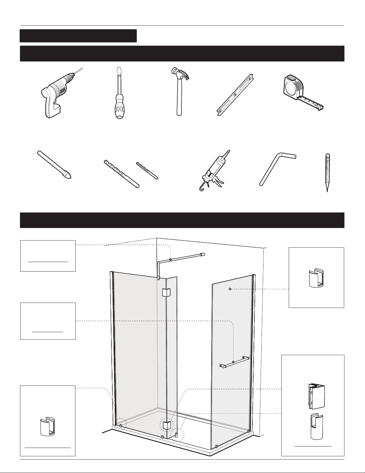
1a. Using a measuring tape, mark the
center of the threshold of the base.
1b. Using the marking established in the
previous step, run a second line up the
wall. Use a level to ensure verticality of
this line.
1c. Place the wall jamb (1) onto the wall
while ensuring that the wall jamb holes
align themselves onto the line running
up the wall. Moreover , the side holes of
the wall jamb should face the interior of
the shower . Proceed to drilling, using a
1/8½drill bit, through the wall using the
wall jamb holes as a reference.
1d. Insert a drop of silicone into each hole
made in the previous step. Following
that, insert an orange wall plug (10.1)
into each hole and from there the wall
jamb can be repositioned and
permanently fastened using #8-1 1/4
Self drilling screws (10.3).
1a
1b
1d
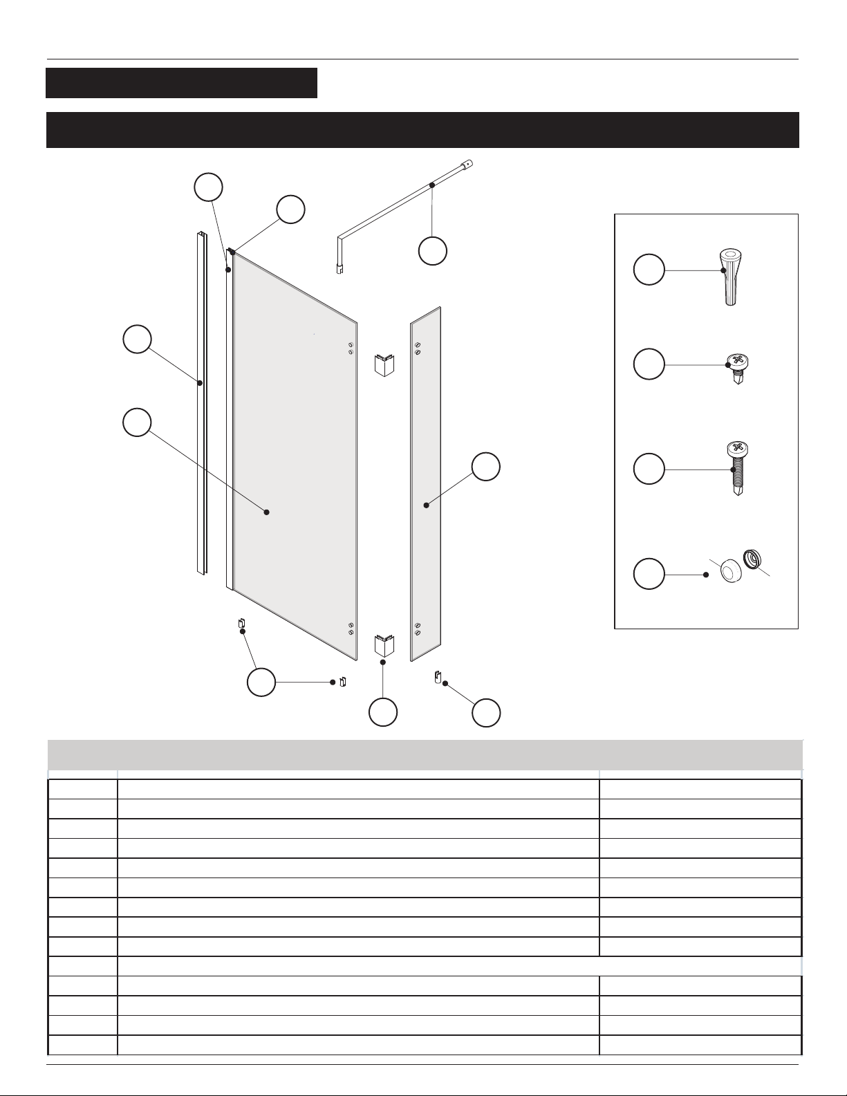
1
1
10.1
10.3
THIS INSTALLATION PROCEDURE APPLIES FOR
ALL RETURN PANELS INSTALLATION
REGARDLESS QUANTITY OR ADITTIONAL
FIXTURE AS TOWEL BAR.
7
1c
FRONT PANEL
203X, 313X, 313TBX
INSTALLATION